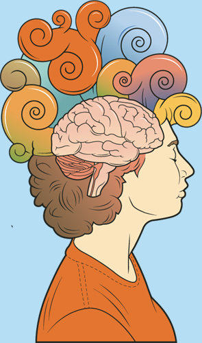
THE BRAIN MACHINE

Photography by Sam Murphy
RIDE YOUR OWN BRAIN WAVES
You don’t have to be a Buddhist monk to meditate, or a Sleeping Beauty to sleep well. Achieve these altered states of consciousness, and others, with this simple microcontroller device.
What would happen if you could play a recording of brain waves into someone’s brain? That question popped into my mind one day while I was meditating, and it turns out that there are devices that can do this. Sound and Light Machines (SLMs) produce sound and light pulses at brain wave frequencies, which help people sleep, wake up, meditate, or experience whatever state of consciousness the machine is programmed for. The first time I tried one was a trip! Not only did I follow the sequence into a deep meditation and then out again (feeling wonderful!), but along the way I had beautiful, outrageous hallucinations.
This article shows you how to build an SLM for much cheaper than you can buy one. We’ll do it the easy way, by hacking a microcontroller project that already exists: Limor Fried’s MiniPOV kit. This cool toy blinks pictures and words in the space you wave it through, and we can transform it into an SLM simply by changing the firmware and some minor hardware.
Set up: p.92 Make it: p.93 Use it: p.99
Best known for inventing TV-B-Gone, a keychain that turns off TVs in public places, Mitch Altman is interested in any technology that gives people more choices for improving their lives.
HOW SOUND AND LIGHT HACK THE BRAIN
The brain produces varying proportions of brain wave types, depending on its current levels of relaxation, focus, and other mental states. Each type of wave has its own characteristic frequency range, which can be read by electroencephalography. Many people’s brain waves will synchronize to lights and sounds pulsing at brain wave frequencies, and this makes the brain change its state — a process called “entrainment.” By playing sequences of pulses into your eyes and ears, you can program your brain to follow any brain wave experience you like.
The brain wave spectrum divides into 5 bands with different associated states:
![]() DELTA WAVES (δ), ½–4Hz: Deep unconscious, intuition and insight
DELTA WAVES (δ), ½–4Hz: Deep unconscious, intuition and insight
![]() THETA WAVES (θ), 4–8Hz: Subconscious creativity, deep relaxation
THETA WAVES (θ), 4–8Hz: Subconscious creativity, deep relaxation
![]() ALPHA (α) waves, 8–13Hz: “Spacey” and dreamy state, receptive and passive
ALPHA (α) waves, 8–13Hz: “Spacey” and dreamy state, receptive and passive
![]() BETA (β) waves, 13–30Hz: Conscious thought, external focus
BETA (β) waves, 13–30Hz: Conscious thought, external focus
![]() GAMMA (γ) waves, 30–100Hz: Not well understood, but linked to perception and alertness or anxiety
GAMMA (γ) waves, 30–100Hz: Not well understood, but linked to perception and alertness or anxiety
Illustrations by Timmy Kucynda
During successful meditation, the subject typically starts off with high beta (thinking), then experiences more alpha, followed by more theta and finally delta, the deepest level. After some time, the reverse process takes place, bringing the person back to beta feeling awake and refreshed, sometimes with new insights.
HOME ENTRAINMENT SYSTEM
We’ll program our SLM to follow a 14-minute sequence that tracks the meditation experience. Since the device generates only one frequency at a time, it phases in new brain states by switching frequencies back and forth. For example, to go from fully awake to somewhat dreamy, we generate beta for a while, then alpha, then toggle between beta and alpha, reducing the duration of beta and increasing that of alpha with each iteration. Our code’s brainwaveTab array defines the full sequence.

Instead of simply playing the entraining wave frequency through both headphone speakers, we employ a more effective method. When we play different frequencies into each ear, the brain perceives a binaural beat frequency just as if the two tones were played next to each other on guitar strings. The beat results from the two tones cyclically reinforcing and canceling each other out, at a rate that equals the difference between the frequencies.
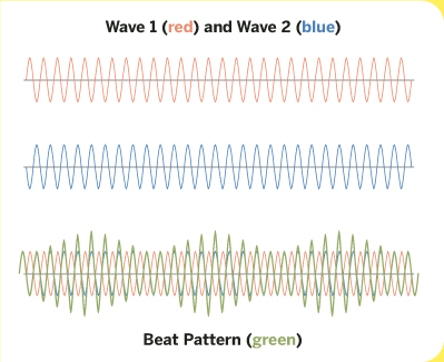
To generate a beta binaural beat, we play a 400Hz tone in one ear and a 414.4Hz tone in the other. The user perceives a sound, sort of like “wah-oo-wah-oo-wah,” that fades in and out 14.4 times per second.
SET UP.
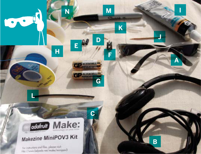
MATERIALS
[A] Safety glasses from your favorite hardware store
[B] Headphones Cheap ones, like the free ones on airplanes
[C] MiniPOV v3 kit $18 from makezine.com/go/povkit. SLM firmware downloadable with full documentation from makezine.com/10/brainwave
[D] 1kΩ resistors, ¼W (2) Mouser Electronics (mouser.com) part #660-CF1/4C102J
[E] 1.0μF capacitors, bipolar (2) Mouser #647-UVP1H010MDD
[F] 3.5mm stereo jack that mates with your headphones, Mouser #161-3402
[G] AA batteries (2)
[H] Kynar wire Also known as 30-gauge wire-wrap wire, any 2 colors; I used blue and yellow, RadioShack #278-502 and #278-503.
[I] Silicone adhesive Also known as RTV (room temperature vulcanizing); clear or any other color, about $5 from your favorite hardware store
[J] Toothpicks for spreading silicone adhesive
[K] Cable ties, 4" long x 0.1" wide (6) Mouser #517-41932
[L] 4" length of 5" heat-shrink tubing Mouser #5174-11161
[M] Permanent or dry-erase marker
[N] 3M Magic Tape
Eye graphics (optional) Download and print the template I used at makezine.com/10/brainwave.
Rubbing alcohol and toilet paper for removing permanent marker marks, if you make a mistake
Total materials cost should be $23–$56, depending on what you can scrounge.
TOOLS
Computer with 9-pin serial port or a USB port and a USB/serial adapter based on the PL2303-chipset, about $15 for port
Soldering equipment and solder
Needlenose pliers
Diagonal cutters
Wire strippers
Drill and 3/16" drill bit
Small, sharp nail
“Third hand” tool (optional) Very handy
Scissors, hobby knife, printer (optional) for graphics
MAKE IT.

BUILD YOUR SOUND AND LIGHT MACHINE
Time: An Afternoon Complexity: Medium Easy
START ≫
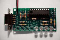
1. BUILD AND TEST-PROGRAM THE PCB
The core of our electronics is the MiniPOV v3 kit. We’ll be referring to the kit’s website at ladyada.net/make/minipov3.
1a. Follow the excellent instructions on the MiniPOV website to solder all the components to the included printed circuit board (PCB) except the following: LED1, LED2, LED3, LED4, R5, R6. Go ahead and leave these 6 components out.
NOTE: In electronics-speak, soldering a component onto a PCB is called “stuffing” it.
1b. Insert the 2 AA batteries into the battery holder and switch on. The microcontroller will run the MiniPOV firmware, and the 4 stuffed LEDs should light up.
1c. If the LEDs don’t light up, then debug. Are the batteries in correctly? Check the power connections. Check for bad solder connections or solder bridges (shorts between 2 pads). Check that all LEDs, and D1, D2, and D3, are not stuffed backwards. Now we’ll change the MiniPOV’s firmware so you can learn how to use the development tools and see how easy it is.
1d. Download and install the AVRDUDE software needed for your operating system. Links for the software are on the MiniPOV website listed above, under “Download.” If you’re using a USB/serial adapter, also download the USB/serial converter driver.
1e. Create a folder on your computer called slm. Download the firmware for MiniPOV from the MiniPOV website into the slm folder and unzip it. Using a text editor, open up the mypov.c file, and change the pattern in the image array (near the top of the file) to the pattern at right. Since a 1 will light up an LED and a 0 leaves it off, this will create a pattern on 4 LEDs that looks something like “VVVVV” when you wave the MiniPOV back and forth through the air. Switch off the MiniPOV’s battery pack, plug the MiniPOV into your computer’s serial port, and switch it back on.
B8(10000000)
B8(01000000)
B8(00100000)
B8(00010000)
B8(00100000)
B8(01000000)
1f. Compile and program the microcontroller by following the instructions on the MiniPOV website for your operating system. Under Windows, you’ll enter the following (at right) into a command window. Turn the MiniPOV power pack off and unplug the PCB from the serial port. Switch the power back on and the 4 LEDs will light up. Wave it around, and behold the VVVVV pattern you just programmed in!
> cd slm
> del mypov.hex
> make mypov.hex
> make program-mypov
NOTE: make mypov.hex compiles the code into a hex file that the microprocessor can run, and make program-mypov uploads the hex through the serial port to the microprocessor.
2. MAKE THE SLM CONTROLLER
2a. Download SLMfirmware.zip from makezine.com/10/brainwave into your slm directory and unzip it. Let it overwrite the makefile with the new one if asked. Program the microcontroller with the new firmware. Follow Step 1e above to hook it up to your computer. Then compile and upload the firmware to the micro. The process is identical to Step 1f, but we’re programming slm instead of mypov. Under Windows, enter the code seen to the right.
> cd slm
> del slm.hex
> make slm.hex
> make program-slm
2b. Turn off and unplug the MiniPOV, which is now an SLM controller, although it won’t do much, since we don’t have any outputs hooked up yet. Solder the two 1μF capacitors into the pads for LED3 and LED4. Solder the two 1kΩ resistors into the pads for R5 and R6. Clip the excess leads on the back of the PCB.
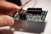
NOTE: Adding the capacitors and resistors creates low-pass filters that smooth out the square waves into sine waves, for more pleasing audio.
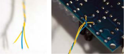
2c. Cut a 2" length of blue wire for hooking up the stereo headphone jack (for ground). Cut two 2" lengths of yellow wire. Strip 1/8" off one end of each wire, and tin.
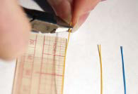
NOTE: To “tin” a wire means to heat it up with the soldering iron and melt a little solder on it. This makes it easier to solder it to something else.
2d. Place the stripped end of the blue ground wire into the headphone jack’s ground terminal and solder. Place one of the yellow speaker wires into one of the jack’s empty terminals and solder. Do the same for the remaining speaker wire.

NOTE: There are 3 terminals on the headphone jack. One is ground, offset from the others, and the other 2 are for the left and right speakers. For this project it doesn’t matter which way we connect the left and right speakers.
2e. Twist these 3 wires neatly, but leave about ½" untwisted. Cut them so that they all extend the same length, strip 1/32" off each, and tin. Solder the ground wire (blue) to the PCB trace that connects all of the LED grounds together. Then solder the right and left speakers (yellow) to the outputs for LED3 and LED4.
2f. Test the audio by plugging your headphones into the jack, putting them on, and flipping the power switch. You should hear some spacey sounds in both ears. If not, the most likely problems are bad solder connections or solder bridges.
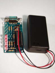
3. PREPARE THE BATTERY PACK
3a. Unsolder the 2 battery pack wires from the PCB.
3b. Cut two 4" lengths of wire (1 yellow, 1 blue), strip 1/8" off 1 side of each, and tin the stripped ends.

NOTE: Although you can use electrical tape to cover the exposed wires, heat-shrink looks nicer and won’t unravel.
3c. Hold the blue wire to the black battery pack wire (negative) and solder them together. Slip ½" of heat-shrink tubing over the connection and lightly rub the tubing back and forth on all sides with the soldering iron for a few seconds until the tubing shrinks around the connection. Repeat for the red battery pack wire (positive), but use yellow wire to extend it.
4. PREPARE THE GLASSES
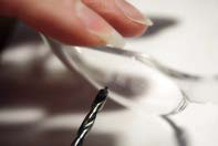
4a. The glasses need 1 LED facing each eye. Place the glasses on your face, look straight ahead, and point the tip of a marker at your right eye. Slowly move the marker toward your eye to make a mark directly in front of your eye. Repeat for left eye. If you want to cover the glasses with cool graphics, trace the shape of each lens onto a piece of paper, and cut the 2 templates out for later.

NOTE: The marks on the glasses should be somewhat symmetrical. If not, use some toilet paper and rubbing alcohol to remove the marks and try again.
4b. Use a small sharp nail to make a pilot indentation into the 2 marks on the glasses. Drill a 3/16" hole for each eye, taking care not to let the bit slip. Test-fit the leftover LEDs from the MiniPOV kit into the holes. If you can’t push them all the way in, enlarge the holes a little by pushing the sides against the spinning drill bit.
4c. Push an LED into each eye hole so that they will face your eyes when you wear the glasses. Cut four 8" lengths of wire (2 yellow, 2 blue), strip 1/8" off 1 side of each, and tin the stripped ends.
4d. The longer lead of each LED is the positive lead. Cut off all but 1/8" of the positive leads for each LED, tin them, and solder them to 8" yellow wires. Do the same for the negative leads, soldering them to the blue wires.

NOTE: Cut the leads one at a time, to make sure you don’t confuse the positive and the negative.
4e. Bend the wires on both LEDs up and over the top edge of the glasses and glue each LED into place from the outside using silicone adhesive. Use a toothpick to create a solid hemisphere of silicone that makes good contact with the glasses and coats the LED leads and exposed wire. Let the adhesive harden (1–2 hours).

NOTE: Silicone adhesive is a good choice for electronics projects because it does not conduct electricity and is easy to use.
5. ATTACH THE BATTERY PACK AND PCB
5a. Prepare 2 pairs of cable ties by slipping one about ¾" through the other.
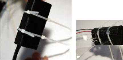
NOTE: Using 2 short cable ties instead of 1 long one makes it cleaner to go around corners.
5b. Spread silicone adhesive 25/8" along the right temple of the glasses to span the length of the battery pack. Press the battery pack into the adhesive and secure with the double cable ties. Trim the excess length off the cable ties and then let the adhesive harden.
5c. Route the 4 wires from the LEDs and 2 from the battery pack along the top of the glasses toward the left temple (where they will connect to the PCB), twisting them together along the way. Keep the 2 wires from the battery pack together, so you don’t confuse them with the LED wires.
5d. Hold the PCB in place on the left temple (but don’t glue yet), positioning it such that the connector sticks in front of the left lens when the glasses are unfolded. This will let you plug the glasses into your computer. Trim the 6 wires so that there will be only a little bit of slack when they connect to the LEDs and battery pack. Strip 1/16" off the end of each of the 6 wires, and solder them to the unstuffed LED and battery pack contacts, maintaining proper polarity.

NOTE: Test the LEDs by turning on the battery pack power switch. The LEDs on the glasses should flash. If not, then double-check the wiring.
5e. Spread silicone adhesive 2¼" along the left temple of the glasses for the length of the PCB. Press the PCB into the adhesive and secure with another cable tie pair. Remember that the connector needs to plug into your computer’s serial port without the glasses getting in the way. Clip any excess wire under the PCB and cut the excess off the cable ties.
6. SECURE THE HEADPHONE JACK AND LOOSE WIRES
6a. Push the wires to the side, put a blob of silicone over D2 and R11 on the PCB, and push the headphone jack sideways into the blob. Add more adhesive with a toothpick to completely cover the terminals of the jack and about the first 1/8" of each attached wire.

NOTE: Gluing the wires and terminals will prevent shorts and provide strain relief.
6b. To hold the loose wires in place while they are being glued, prepare eight 4" strips of Magic Tape by folding a small bit of each end over to stick onto itself. Stick the tape pieces where you can reach them while gluing the wires to the glasses in the next step.

NOTE: Doubling the ends over makes it much easier to pull off the tape strips after the adhesive hardens.
6c. Use a toothpick to thinly spread silicone adhesive between the wires and along the top of the glasses, then glue the wires along the glasses. Use the tape strips to keep the wires in place while the adhesive hardens. Also tape the headphone jack in place. Wait for the adhesive to harden, about 1–2 hours, then remove the tape.

7. APPLY COOL GRAPHICS (OPTIONAL)
7a. Using the templates you created earlier, cut out lens-shaped pieces from your graphics for the left and right lenses. Cut a hole in each one where the back of the LEDs will poke through.

7b. Apply a very thin layer of silicone adhesive (spread with your finger) in a horizontal strip on the back of each cutout. Affix them to the front of the glasses. Now they look cool!
FINISH X
NOW GO USE IT »
USE IT.

TRIP THE LIGHT FANTASTIC
Get comfortable, put on the glasses and headphones, close your eyes (the LEDs are bright!), and flick the power switch. Enjoy the hallucinations as you drift into deep meditation, ponder your inner world, and then come out after the 14-minute program feeling fabulous.
New to meditating? Here are a few ideas. Breathe normally and pay attention to your breathing. If you space out, no worries — just focus on your breathing again. Or don’t focus on anything; follow your thoughts wherever they go. You can also concentrate on something before you start: solving a technical problem, exploring a difficult decision, feeling through the issues in a relationship. If you space out, just refocus on your intent. There is no end to the variety of what you can do in a meditative state.
![]() CAUTIONS: Blinking lights should be avoided by anyone prone to seizures. If you are sensitive to seizures, please disconnect the LEDs in this project; your brain can effectively entrain with the binaural audio beat alone. Certain conditions, such as ADHD, can worsen with theta and delta entrainment. Please discontinue using this SLM if you experience any problems.
CAUTIONS: Blinking lights should be avoided by anyone prone to seizures. If you are sensitive to seizures, please disconnect the LEDs in this project; your brain can effectively entrain with the binaural audio beat alone. Certain conditions, such as ADHD, can worsen with theta and delta entrainment. Please discontinue using this SLM if you experience any problems.
PROGRAMMING YOUR OWN BRAIN WAVE SEQUENCES
You can program your own sequence by editing the brainwaveTab definition in the file slm.c. Each line defines a pair (bwType, bwDuration) that sets the brain wave type for an amount of time, specified in tenthousandths of a second. For example, the first pair, { 'b', 600000 }, runs the beta frequency (14.4Hz) for 60 seconds.
You can program the session to last longer than 14 minutes, spending more time in deeper states. To aid sleep, you may also want to decrease the pitch of the audio, since lower pitches are more relaxing. You can do this by tweaking the OCR0A setting in main and the OCR1A settings in the function do_brainwave_element, also in the file slm.c. Explore and enjoy!
BRAIN MACHINE II
I’m working on a more complex SLM with many improvements to enhance relaxation and entrainment. It will gently fade sound and lights in and out, handle multiple simultaneous frequencies, match brain wave types to different colored LEDs and binaural base frequencies, and mask the binaural beats with music or other sounds. Physically, it will fit in a soft fabric sleep mask and use a light, flexible, rechargeable battery. It will have other enhancements as well; I’ll keep the MAKE community posted.
RESOURCES
Megabrain Power: New Tools and Techniques for Brain Growth and Mind Expansion
by Michael Hutchison, Ballantine Books, 1996
The High-Performance Mind
by Anna Wise, Tarcher, 1997
Dreamachine Plans
by Brion Gysin, Temple Press, 2006
The Anna Wise Center: annawise.com
The Monroe Institute: monroeinstitute.com
AVR Freaks (microcontroller forum): avrfreaks.net
![]() More resources at makezine.com/10/brainwave
More resources at makezine.com/10/brainwave