Part 2
Mastering Intermediate Skills
- Chapter 6: Editing and Reusing Data to Work Efficiently
- Chapter 7: Mastering Viewing Tools, Hatches, and External References
- Chapter 8: Introducing Printing, Plotting, and Layouts
- Chapter 9: Understanding Plot Styles
- Chapter 10: Adding Text to Drawings
- Chapter 11: Using Fields and Tables
- Chapter 12: Using Dimensions
Chapter 6
Editing and Reusing Data to Work Efficiently
If you’re an experienced drafter, you know that you frequently have to draw the same item several times in many drawings. The AutoCAD® 2013 software offers a variety of ways to reuse existing geometry, thereby automating much of the repetitive work usually associated with manual drafting. That’s why at least 5 commands are devoted to duplicating objects—10 if you include the grips options.
In this chapter, as you finish drawing the studio apartment unit, you’ll explore some of the ways to exploit existing files and objects while constructing your drawing. For example, you’ll use existing files as prototypes for new files, eliminating the need to set up layers, scales, and sheet sizes for similar drawings. With AutoCAD, you can also duplicate objects in multiple arrays. In Chapter 3, “Setting Up and Using the Drafting Tools,” you saw how to use the object snap (osnap) overrides on objects to locate points for drawing complex forms. This chapter describes other ways of using lines to aid your drawing.
Because you’ll begin to use the Zoom command more in the exercises in this chapter, you’ll review this command as you go along. You’ll also discover the Pan command—another tool to help you get around in your drawing.
You’re already familiar with many of the commands you’ll use to draw the apartment unit. So, rather than going through every step of the drawing process, the exercises will sometimes ask you to copy the drawing from a figure and, using notes and dimensions as guides, put objects on the indicated layers. If you have trouble remembering a command you’ve already learned, go back and review the appropriate section of the book.
In this chapter, you will learn to:
- Create and use templates
- Copy an object multiple times
- Develop your drawing
- Find an exact distance along a curve
- Change the length of objects
- Create a new drawing by using parts from another drawing
Creating and Using Templates
Most programs today include what are called templates. A template is a file that is already set up for a specific application. For example, in your word processor you might want to set up a document with a logo, a return address, and a date so you don’t have to add these elements each time you create a letter. You might also want to format invoices in a slightly different way. You can set up a template for the needs of each type of document. That way, you don’t have to spend time reformatting each new document you create.
Similarly, AutoCAD offers templates, which are drawing files that contain custom settings designed for a particular function. Out of the box, AutoCAD has templates for ISO, ANSI, DIN, GB, and JIS standard drawing formats that include generic title blocks. But you aren’t limited to these “canned” templates. You can create your own templates for your particular style and method of drawing.
If you find that you use a particular drawing setup frequently, you can turn one or more of your typical drawings into a template. For example, you might want to create a set of drawings with the same scale and sheet size as an existing drawing. By turning a frequently used drawing into a template, you can save a lot of setup time for subsequent drawings.
Creating a Template
The following exercise guides you through creating and using a template drawing for your studio’s kitchenette. Because the kitchenette will use the same layers, settings, scale, and sheet size as the bathroom drawing, you can use the Bath file as a prototype. Follow these steps:
1. Start AutoCAD in the usual way.
2. Choose Open from the Quick Access toolbar to open the Select File dialog box.
3. Locate the Bath file you created in the previous chapter. You can also use the file 06-bath.dwg from the DVD.
4. Click the Erase button on the Home tab’s Modify panel, or enter
E↵; then type
all↵↵. This erases all the objects that make up the bathroom, but other elements, such as layers, linetypes, and stored blocks, remain in the drawing.
5. Choose Save As from the Application menu to open the Save Drawing As dialog box.
6. Open the File Of Type drop-down list, and select AutoCAD Drawing Template (*.dwt). The file list window changes to display the current template files in the Template folder.
7. In the File Name text box, enter the name Arch8x11h. If you’re a metric user, enter the name A4plan.
8. Click Save to open the Template Options dialog box (see
Figure 6-1).
9. Enter the following description: Architectural one inch scale drawing on 81/2 by 11 inch media. Metric users should enter the description Architectural 1:10 scale drawing on A4 media.
10. Select English or Metric from the Measurement drop-down list, depending on the unit system you’re using.
Locating the Template Folder
When you choose the AutoCAD Drawing Template option in the Save Drawing As dialog box, AutoCAD automatically opens the folder containing the template files. The standard AutoCAD installation creates the folder named Template to contain the template files. If you want to place your templates in a different folder, you can change the default template location by using the Options dialog box (choose Options from the bottom of the Application menu). Click the Files tab, double-click to expand Template Settings, and then double-click Drawing Template File Location in the list. Double-click the folder name that appears just below Drawing Template File Location; then select a new location from the Browse For Folder dialog box that appears.
11. Click the Save All Layers As Reconciled option.
12. Click OK to save your new file and create a template. The template file you saved becomes the current file. (As with other Windows programs, choosing File ⇒ Save As makes the saved file current.) This exercise shows that you can edit template files just as you would regular drawing files.
13. Close the template file.
Using a Template
Now let’s see how a template is used. You’ll use the template you just created as the basis for a new drawing you’ll work on in this chapter:
1. Click the New tool from the Quick Access toolbar to open the Select Template dialog box. This is a typical file dialog box with which you should be familiar by now.
2. In the Select Template list box, click the filename Arch8x11h.dwt. Metric users should click the filename A4plan.dwt. Because this file is blank, you won’t see anything in the preview window.
3. Click Open. It may not be obvious, but your new file is set up with the same architectural units and drawing limits as the bathroom drawing. It also contains the Door, Toilet, and Tub blocks.
4. You need to give your new file a name. Choose Save As from the Application menu to open the Save Drawing As dialog box. (Make sure you choose Save As, or you won’t get the Save Drawing As dialog box.) Enter Kitchen for the filename, and select the folder in which to save your new kitchen file. For example, you can save your file in the My Documents folder by clicking the My Documents shortcut in the left column.
5. Click Save to create the Kitchen file, and close the dialog box.
You’ve created and used your own template file. Later, when you’ve established a comfortable working relationship with AutoCAD, you can create a set of templates that are custom-made to your particular needs.
However, if you’re in a hurry, you don’t need to create a template every time you want to reuse settings from another file. You can use an existing file as the basis or prototype for a new file without creating a template. Open the prototype file, and choose Save As from the Application menu to create a new version of the file under a new name. You can then edit the new version without affecting the original prototype file.
Copying an Object Multiple Times
Let’s explore the tools that let you quickly duplicate objects. In the following sections, you’ll begin to draw parts of a small kitchen. The first set of exercises introduces the Array command, which you can use to draw the gas burners of a range top.
As you’ll see, an array can be either in a circular pattern, called a polar array, or a matrix of columns and rows, called a rectangular array. You can also create arrays that follow a curved or straight path, such as a spline curve, arc, or polyline.
Making Circular Copies
To start the range top, first set the layer on which you want to draw, and then draw a circle representing the edge of one burner:
1. Set the current layer to Fixture by selecting Fixture from the layer drop-down list in the Home tab’s Layers panel.
Because you used the Bath file as a template, Running Osnap is already turned on for Endpoint, Midpoint, and Intersection.
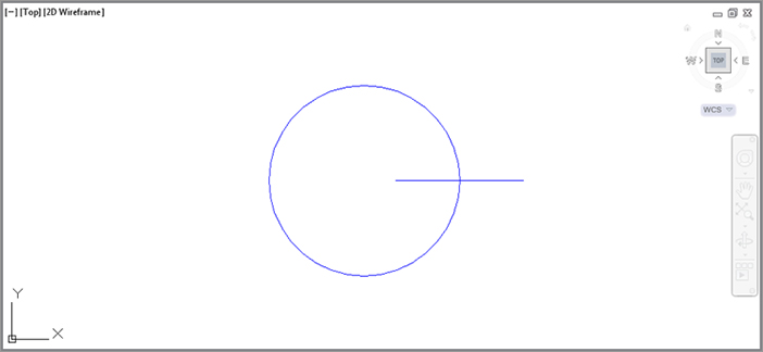
2. Click the Center, Radius Circle tool on the Home tab’s Draw panel, or type
C↵.
3. At the Specify center point for circle or [3P/2P/Ttr (tan tan radius)]: prompt, pick a point at coordinate 4″,4″. Metric users should pick a point at coordinate 120,120.
4. At the Specify radius of circle or [Diameter]: prompt, enter 3↵. Metric users should enter 7.6↵. The circle appears.
Now you’re ready to use the Array command to draw the burner grill. You’ll first draw one line representing part of the grill and then use the Array command to create the copies:
1. Zoom into the circle you just drew, and then make sure Snap mode is off by checking the Snap Mode tool in the status bar.
2. Draw a 4′ line starting from the coordinate 4″-1′,4″-0′ and ending to the right of that point. Metric users should draw a 9 cm line starting at coordinate 122,120 and ending to the right of that point.
3. Adjust your view so it looks similar to
Figure 6-2.
You’ve got the basic parts needed to create the burner grill. You’re ready to make multiple copies of the line. For this part, you’ll use the Array command:
1. Make sure Ortho mode is off and Polar Tracking is on.
2. Click the Polar Array tool from the Array flyout on the Modify panel as shown in
Figure 6-3, or type
ARRAYPOLAR↵.
3. At the Select Objects: prompt, click the horizontal line and press ↵.
4. At the Specify center point of array or [Base point/Axis of rotation]: prompt, Shift+right-click and select Center. To select the center of the circle, hover over the circle perimeter until you see the Center osnap marker. When the marker appears, click the mouse. A circular array of the line appears.
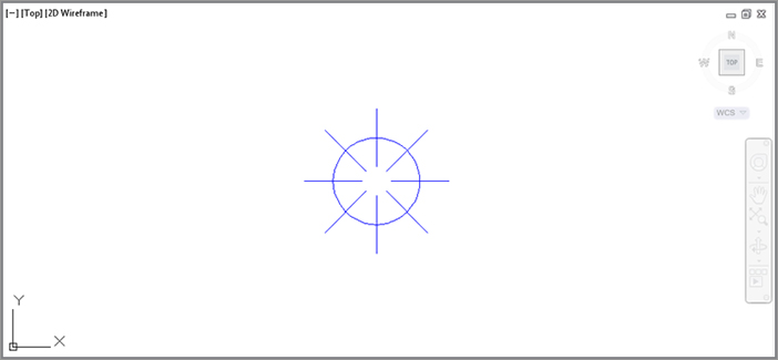
5. At the Select grip to edit array or [Associative/Base point/Items/Angle between/Fill angle/ROWs/Levels/ROTate items/eXit]<eXit>: prompt, enter I↵ or click Items from the command line.
6. At the Enter number of items in array or [Expression]: prompt, enter
8↵. The lines appear evenly spaced in a circular array (
Figure 6-4).
7. Press ↵ to exit the Arraypolar command, or if Dynamic Input is on, choose eXit from the menu that appears at the cursor. Your drawing should look like
Figure 6-4.
Making Row and Column Copies
Now you’ll draw the other three burners of the gas range by creating a rectangular array from the burner you just drew. You’ll first zoom back a bit to get a view of a larger area. Then you’ll proceed with the Array command.
Follow these steps to zoom back:
1. Click Scale from the Zoom tool’s flyout in the View tab’s Navigate 2D panel or Zoom Scale from the Navigation bar. You can also type
Z↵
S↵.
2. Enter
0.5x↵. Your drawing will look like
Figure 6-5.
If you’re not too fussy about the amount you want to zoom out, you can click Out from the Zoom flyout on the View tab’s Navigate 2D panel to reduce your view quickly.
Entering 0.5x for the Zoom Scale factor tells AutoCAD you want a view that reduces the width of the current view to fill half the display area, enabling you to see more of the work area. If you specify a scale value greater than 1 (5, for example), you’ll magnify your current view. If you leave off the x, your new view will be in relation to the drawing limits rather than the current view.
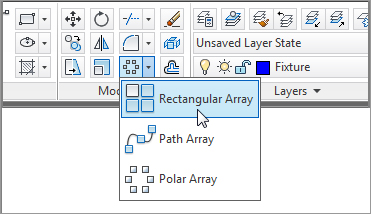
Next you’ll finish the range top. You’ll get a chance to use the Rectangular Array option to create three additional burners:
1. Click the Rectangular Array tool on the Array flyout on the Modify panel as shown in
Figure 6-6, or type
ARRAYRECT↵.
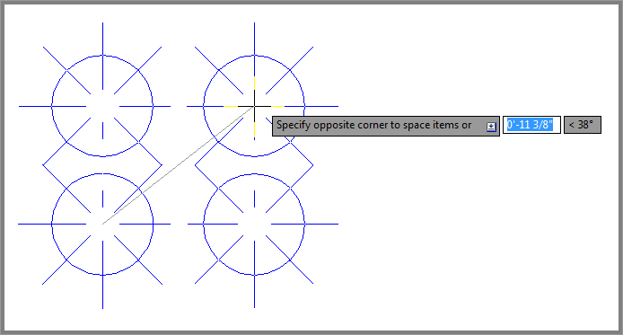
2. Select the entire burner, including the lines and the circle, and then press ↵ to confirm your selection.
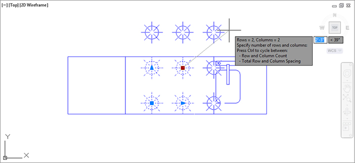
3. At the Select grip to edit array or [Associative/Base point/COUnt/Spacing/Angle/COLumns/Rows/Levels/eXit]<eXit>: prompt, type COU↵ or click COUnt from the command line.
4. At the Enter number of rows or [Expression] <4>: prompt, enter 2↵.
5. At the
Enter number of columns or [Expression] <4>: prompt, enter
2↵ again. Now, as you move the cursor, you’ll see a preview of the array, as shown in
Figure 6-7.
6. To set the array dimensions, type S↵ or select Spacing from the command line.
7. At the Specify the distance between columns or [Unit cell] <1’-3”]: prompt, type 1″-4′↵. Metric users enter 40.6↵.
8. At the Specify the distance between rows <1’-3”>: prompt, type 1″-2′↵. Metric users enter 35.5↵.
9. Press ↵, or if Dynamic Input is on, click the eXit option in the menu at the cursor.
10. The array appears in the drawing, but a few of the array elements are off the top of the screen, as shown in
Figure 6-8. In the next section, “Fine-Tuning Your View,” you’ll learn about the Pan tool, which will enable you to adjust the view so that the array is centered in the drawing area.
At times, you may want to create a rectangular array at an angle. You can accomplish this by using the Angle option. The Angle option appears after you have selected the objects for the array and before you enter the row and column values. You’ll see the prompt Select grip to edit array or [Associative/Base point/COUnt/Spacing/Angle/COLumns/Rows/Levels/eXit]<eXit>:. Type A↵, and you’ll see the prompt Specify row axis angle <0>:. You can enter an angle value or indicate an angle with your cursor (Figure 6-9).
Quick Array Copies with Grips
Sometimes the Array tool can be overkill if you only need to make a few evenly spaced copies. Fortunately, grip editing offers a feature that lets you quickly make evenly spaced copies. Here’s how it’s done:
1. Press the Esc key to make sure you aren’t in the middle of a command; then select the objects you want to copy.
2. Click a grip point as your base point.
3. Right-click your mouse and select Move.
4. Ctrl+click a location at which to place a copy of the selected object. This first copy will determine the interval distance for additional copies.
5. Continue to hold down the Ctrl key, and select additional points to make copies at regularly spaced intervals.
The copies snap to the distance you indicate with the first Ctrl+click point (in step 4). You can use osnaps to select a distance based on the position of another object. Once you’ve made the first copy with the Ctrl+click, you can release the Ctrl key to make multiple copies at random intervals. Another option is to use PolarSnap while making grip edit copies. With PolarSnap, you can enter a specific distance for the intervals.
Fine-Tuning Your View
Back in Figure 6-8, you may have noticed that parts of the burners don’t appear on the display. To move the view over so that you can see all the burners, use the Pan command. Pan is similar to Zoom in that it changes your view of the drawing. However, Pan doesn’t alter the magnification of the view the way Zoom does. Rather, Pan maintains the current magnification while moving your view across the drawing, just as you would pan a camera across a landscape.
To activate the Pan command, follow these steps:
1. Click the Pan tool on the View tab’s Navigate 2D panel or from the Navigation bar, or type
P↵. You can also right-click and choose Pan from the context menu. A small hand-shaped cursor appears in place of the AutoCAD cursor.
2. Place the hand cursor in the center of the drawing area, and then click and drag it down and to the left. The view follows the motion of your mouse.
3. Continue to drag the view until it looks similar to
Figure 6-10; then release the mouse button.
4. To finish the kitchen, you want a view that shows more of the drawing area. Right-click to open the Zoom/Pan context menu, and then choose Zoom. The cursor changes to the Zoom Realtime cursor. The Zoom/Pan context menu also appears when you right-click during the Zoom Realtime command.
5. Place the cursor close to the top of the screen, and click and drag the cursor down to zoom out until your view looks like the top panel of
Figure 6-11. You may need to click and drag the Zoom Realtime cursor a second time to achieve this view.
6. Right-click the mouse again, and choose Close Preview Window from the context menu. You’re now ready to add more information to the kitchen drawing.
You can also exit the Pan or Zoom Realtime command without opening the context menu; just press the Esc key.
This exercise showed how you can fine-tune your view by easily switching between Pan and Zoom Realtime. After you get the hang of these two tools working together, you’ll be able to access the best view for your needs quickly. The other options in the context menu—Zoom Window, Zoom Original, and Zoom Extents—perform the same functions as the options in the Zoom flyout on the View tab’s Navigate 2D panel or in the Navigation bar.
The Zoom Window option in the Zoom/Pan context menu functions in a slightly different way from the standard Zoom Window option. Instead of clicking two points, you click and drag a window across your view.
While we’re on the subject of display tools, AutoCAD offers scroll bars to the right and bottom of the AutoCAD drawing area. They work like any other Windows scroll bar, offering a simple way to move up, down, left, or right in your current view. Scroll bars also come in handy for quickly panning your view in one direction or another.
By default, the scroll bars are turned off. If you prefer to work with them on, open the Options dialog box (choose Options from the Application menu), click the Display tab, look in the Windows Elements group, and make sure the Display Scroll Bars In Drawing Window option is selected. Clear the box to turn them off.
Finishing the Kitchenette
Before you save and close the Kitchen file, you need to do one more thing. You’ll be using this drawing as a symbol and inserting it into the overall plan of the studio apartment unit. To facilitate accurate placement of the kitchen, you’ll change the location of the base point of this drawing to the upper-left corner of the kitchen. This will then be the drawing’s grip:
1. Complete the kitchenette as indicated in the bottom panel of
Figure 6-11, shown earlier in this chapter. As the figure indicates, make sure you put the kitchenette on the Fixture layer. This will help you control the visibility of the kitchenette in future edits of this file. Draw the sink roughly as shown in the figure.
2. Click the Set Base Point tool in the Home tab’s expanded Block panel.
3. At the
Enter base point: prompt, pick the upper-left corner of the kitchen, as indicated in the bottom image of
Figure 6-11. The kitchen drawing is complete.
4. Click Save from the Quick Access toolbar, but keep the file open because you’ll use it later.
Using the Copy Command to Create an Array
In the previous section, you learned how you can quickly make an array of objects using the Array command. You can also create simple arrays using the Copy command. To see firsthand how this works, see “Copying and Editing Attribute Definitions” in Chapter 13, “Using Attributes.”
Array Along a Path
Before you continue with the apartment drawings you’re working on for the main part of the tutorial, we’d like to introduce you to one more Array feature. In AutoCAD 2013, you can create an array that follows a curved or straight path, such as an arc, spline curve, or complex polyline. Try the following exercise to see firsthand how it works:
1. Open the file called seating.dwg. You’ll see a drawing of a chair in the lower-left corner along with an arc drawn across the width of the drawing area.
2. Click the Path Array tool in the Array flyout (see
Figure 6-12), or type
ARRAYPATH↵.
3. At the
Select object prompt, click the chair at the left end of the arc in the drawing and then press ↵ (see
Figure 6-13).
4. At the Select Path curve: prompt, select the arc toward the left end.
5. At the Select grip to edit array or [Associative/Method/Base point/Tangent direction/Items/Rows/Levels/Align items/Z direction/eXit] <eXit>: prompt, press ↵ to exit the command.
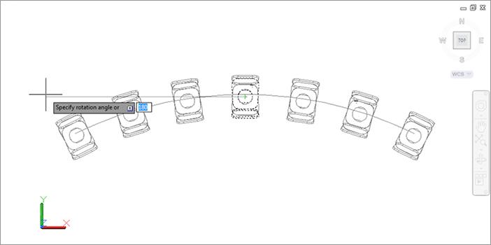
In this exercise, you made an array of a chair that follows the path of an arc. Note that the chair had been set up facing away from the center of the arc. In a later exercise, you’ll see how you can easily rotate the chairs to face the center.
You could have used a spline curve or polyline (see Chapter 19, “Drawing Curves,” for more on spline curves and polylines) instead of the arc and the results would have been similar.
Now suppose you want to adjust the curvature of your array. This is just a simple matter of adjusting the shape of the arc as in the following exercise:
1. Click the arc to expose its grips.
2. Click the middle grip, drag it up until the arc dimension shows an Ortho value close to 30.0000 < 90 degrees, and then click the mouse. The array of chairs follows the arc (see
Figure 6-14).
3. Press the Esc key twice to clear your selection of the arc.
Here you see how the associative feature of the Arraypath command enables you to control the array by adjusting the object you used for the path. Arrays can be edited through a variety of methods, as you’ll see in the next section.
Making Changes to an Associative Array
Now let’s take a look at how you can make changes to an array. You may have noticed the Associative option in the Array command’s prompt. By default, the Associative option is turned on, which enables you to edit array objects as a group. You’ll see firsthand how this works in the following exercises.
You’ll start by editing the array you created using the Path Array tool. Since you’ve changed the arc array path, the chairs no longer fill the arc. The last chair to the right is no longer at the end of the arc. This happened because when you changed the arc’s radius, you made it a bit longer. By default, the chair array is set up to maintain the chairs’ distance from each other. You can change that setting so that the chairs fill the arc. Here’s how it’s done:
1. Click the array of chairs. Notice that the Array contextual Ribbon tab appears (see
Figure 6-15).
2. Click the Measure flyout in the Array tab’s Properties panel and then select the Divide Method option. The chairs are now evenly spaced along the arc.
The Divide And Measure options in the Array tabs Properties panel are similar to the Divide and Measure commands. Divide marks off an object into equal parts while Measure marks off an object based on a distance between the marks. You’ll learn more about Divide and Measure in “Finding an Exact Distance along a Curve” later in this chapter.
You may have also noticed that the chairs are pointing away from the center of the arc. You can realign them so they face the center of the arc by making a simple change to the original chair.
The following steps show you how this is done:
1. Click the Edit Source tool in the Array tab’s Options panel.
2. Click the middle chair in the array. The Array Editing State message appears informing you that you need to enter
ARRAYCLOSE to exit the array editing state (see
Figure 6-16).
3. Click OK.
4. Press the Esc key to clear the selection of chairs.
5. Click the middle chair again, and then click the Rotate tool in the Home tab’s Modify panel.
6. For the rotation base point, click the center of the circle in the chair seat.
7. Rotate the chair so that all of the chairs are facing the center of the arc, as shown in
Figure 6-17.
8. When the chairs are oriented so that they are pointing toward the center of the arc, click to fix their location.
9. Click the Save Changes tool in the Edit Array panel to save the change and exit the array editing state. You can also type ARRAYCLOSE↵ and choose Yes in the dialog box that appears.
In this exercise, you saw how editing the source object of an array affects the other array copies. This is the Associative array feature at work. You could have made any number of other changes to the array.
Next, you’ll make changes to the chair array spacing and add a few additional rows. Then you’ll revisit the kitchenette to see how you can edit a nested array.
Try the following exercise to see how the Ribbon can be used to edit an array:
1. Click any chair in the array. Notice again that the Ribbon changes to show the Array tab with some new panels.
2. In the Rows panel, change the Row Count value in the top text box to 3. Two more rows of chairs appear for a total of three rows.
3. Adjust your view so that you can see all of the rows.
4. In the Items panel, change the Item Count value at the top to 10. Now adjust the spacing so that there are 10 chairs in each row.
5. Press the Esc key to clear your selection.
6. Exit the file without saving it so that you can come back and practice with it again.
Unable to Change the Item Count?
If you can’t change the Item Count value in the Items panel, select Divide Method from the Divide/Measure flyout in the Properties panel of the Array tab. The Measure option does not allow you to change the item count because Measure forces a fixed distance between objects in the array. Since the Divide option doesn’t care about the distance between objects, it allows you to change the item count.
As you can see from these exercises, you can easily make changes to an array through the Ribbon panel options in the Array tab. Many of these options are also available through the multifunction grip menus when you have Dynamic Input turned on.
Several other tools become available on the Ribbon panel when you select an associative array. Table 6-1 gives you a rundown of the panels and tools and their function. The tools that appear in the Ribbon will be slightly different depending on whether the array is a polar, rectangular, or path array, but the features they offer are similar to those in the table.
Table 6-1: The panels and tools on the Array tab
| Items |
Controls the number of items, their distance, and the overall width of the array. |
| Rows |
Controls the number of rows, the distance between rows, and the overall distance between the first and last row. A fourth option, Incremental Elevation in the expanded Rows panel, enables you to control the z-axis height of rows for 3D models. |
| Levels |
Controls the number of levels in the z-axis, their spacing, and the overall distance from the first to the last level. |
| Base Point |
Enables you to adjust the base point of the array objects. |
| Measure/Divide |
Controls how the arrayed objects behave when the path is modified. Measure Method maintains the distance between objects when the path object changes in length. Divide Method causes the distance between objects to adjust to changes in the path object’s length. |
| Align Items |
Controls whether the array objects are aligned with the path object. |
| Z Direction |
Controls whether array objects are “banked” with a 3D path object. |
| Edit Source |
Enables you to edit the source object in an array. |
| Replace Item |
Enables you to replace the source object in the array. |
| Reset Array |
Restores erased items and removes overrides. |
In the next exercise, you’ll return to the kitchen drawing to see how you can use grips to modify an array:
1. If you have closed the kitchen drawing, open it again.
2. Make sure you have Dynamic Input turned on.
3. Click the array of burners that you created earlier. The grips appear for the array, and you see the Array tab in the Ribbon as you did earlier.
4. Hover over the grip in the upper-right burner. A menu appears.
5. Select the Row And Column Count option from the menu. Now, as you move the cursor up and to the right, additional burners appear. The farther to the upper right you move the cursor, the more rows and columns appear (see
Figure 6-18).
6. When you see one additional row and column, click the mouse and then press the Esc key to clear your selection. The additional burners are added to the drawing.
7. You don’t really want the changes to be permanent, so click the Undo tool to revert back to the four burners of the original drawing.
8. Close the kitchen drawing without saving it.
In step 5, you used the Row And Column Count multifunction grip option to add rows and columns to an array. This option combines the function of the Rows and Columns panels in the Array tab.
Developing Your Drawing
As mentioned briefly in Chapter 3, when you’re using AutoCAD, you first create the basic geometric forms used in your drawing and then you refine them. In this section, you’ll create two drawings—the studio apartment unit and the lobby—that demonstrate this process in more detail.
First, you’ll construct a typical studio apartment unit by using the drawings you’ve created thus far. In the process, you’ll explore the use of lines as reference objects.
You’ll also further examine how to use existing files as blocks. In Chapter 4, “Organizing Objects with Blocks and Groups,” you inserted a file into another file. The number of files you can insert is limitless, and you can insert files of any size. As you may already have guessed, you can also nest files and blocks; that is, you can insert blocks or files in other blocks or files. Nesting can help reduce your drawing time by enabling you to build one block out of smaller blocks. For example, you can insert your door drawing into the bathroom plan. In turn, you can insert the bathroom plan into the studio unit plan, which also contains doors. Finally, you can insert the unit plan into the overall floor plan for the studio apartment building.
Importing Settings
In this exercise, you’ll use the Bath file as a prototype for the studio unit plan. However, you must make a few changes to it first. After the changes are made, you’ll import the bathroom and thereby import the layers and blocks contained in the bathroom file.
As you go through this exercise, observe how the drawings begin to evolve from simple forms to complex, assembled forms.
Use these steps to modify the Bath file:
1. Open the 06-Bath file you worked on earlier. If you skipped drawing the Bath file in Chapter 5, “Keeping Track of Layers and Blocks,” use the file 05c-bath.dwg (or 05c-bath-metric.dwg).
2. Click the Set Base Point tool in the Home tab’s expanded Block panel, and select the upper-left corner of the bathroom as the new base point for this drawing so that you can position the
Bath file more accurately.
3. Save the Bath file. If you use the sample from the DVD, choose Save As from the Application menu and save it as Bath. You can save it to your Documents folder to keep the original in its unedited state.
4. Click the Close icon in the upper-right corner of the drawing area, or choose Close from the Application menu to close the bath drawing.
Next, you’ll create a new file. But this time, instead of using the Start From Scratch or Use A Template option in the Create New Drawing dialog box, you’ll try the Use A Wizard option:
1. Click New from the Quick Access toolbar to open the Select Template dialog box.
2. Locate and select the acad.dwt template file. Metric users should locate the acadiso.dwt template file.
3. Click Open to open the new file.
4. If you’re using Imperial measurements, choose Drawing Utilities ⇒ Units from the Application menu; then, in the Drawing Units dialog box, select Architectural from the Length group’s Type drop-down list and click OK. Metric users should use the default decimal length type.
5. Type LIMITS↵. At the Specify lower left corner or [ON/OFF] <0'-0",0'-0">: prompt, press ↵ to accept the default drawing origin for the lower-left corner.
6. If you’re using Imperial measurements, enter 528,408↵ at the next prompt. These are the appropriate dimensions for an 81/2′ × 11′ drawing at 1/4′ = 1″-0′ scale. Metric users should enter 1485,1050. This is the work area for a 1:50 scale drawing on an A4 sheet.
7. Click All from the Zoom flyout on the View tab’s Navigate 2D panel or click Zoom All from the navigation bar.
Let’s continue by laying out a typical studio unit. You’ll discover how importing a file also imports a variety of drawing items such as layers and linetypes. Follow these steps:
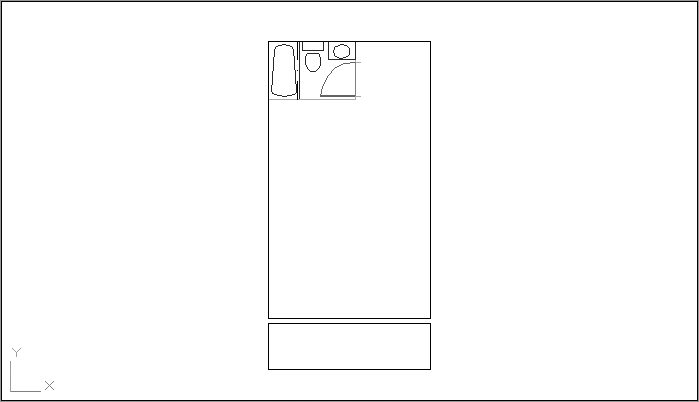
1. Begin the unit by drawing two rectangles, one 14″ long by 24″ wide and the other 14″ long by 4′ wide. Metric users should make the rectangles 426 cm wide by 731 cm long and 426 cm wide by 122 cm long. Place them as shown in
Figure 6-19. The large rectangle represents the interior of the apartment unit, and the small rectangle represents the balcony. The size and location of the rectangles are indicated in the figure.
2. Click the Insert tool on the Home tab’s Block panel to open the Insert dialog box.
3. Click the Browse button, and locate and select the Bath drawing by using the Select Drawing File dialog box; then click Open. If you haven’t saved a bathroom drawing from earlier exercises, you can use 05c-bath.dwg.
If You Used the Rectangle Tool to Draw the Interior and Balcony…
…of the apartment unit, make sure you use the Explode tool on the Modify panel to explode the rectangles. The Rectangle tool draws a polyline rectangle instead of simple line segments, so you need to explode the rectangle to reduce it to its component lines. You’ll learn more about polylines in Chapter 19.
4. If you’re using the 05c-bath.dwg file, do the following: After selecting 05c-bath.dwg in step 3, change the name that appears in the Name text box to Bath instead of 05c-bath before you click OK in step 5. This gives the inserted file a block name of Bath, even though its originating filename is 05c-bath.
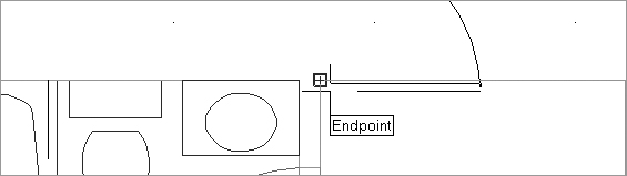
5. Click OK in the Insert dialog box, and then click the upper-left corner of the unit’s interior as the insertion point (see
Figure 6-20). You can use the Endpoint osnap to place the bathroom accurately. If you are prompted for scale and rotation, use a scale factor of 1.0 and a rotation angle of 0°.
6. If running osnaps haven’t been set up in this file, you need to use the Osnap context menu (Shift+right-click) to access the Endpoint osnap. You can set up running osnaps to take advantage of the AutoSnap functions by right-clicking the Object Snap button in the status bar and selecting Settings. Set the running osnaps as described in Chapter 3.
7. Assign the two rectangles that you drew earlier to the Wall layer. To do this, select the two rectangles so that they’re highlighted, and then open the layer drop-down list in the Layers panel and select Wall. Press the Esc key to clear the selection.
By inserting the bathroom, you imported the layers and blocks contained in the Bath file. You were then able to move previously drawn objects to the imported layers. If you’re in a hurry, this can be a quick way to duplicate layers that you know exist in another drawing. This method is similar to using an existing drawing as a template, but it lets you start work on a drawing before deciding which template to use.
Using Osnap Tracking to Place Objects
You’ll draw lines in the majority of your work, so it’s important to know how to manipulate lines to your best advantage. In the following sections, you’ll look at some of the common ways to use and edit these fundamental drawing objects. The following exercises show you the process of drawing lines rather than just how individual commands work. While you’re building walls and adding doors, you’ll get a chance to become more familiar with Polar Tracking and Osnap Tracking.
Roughing In the Line Work
The bathroom you inserted in the preceding section has only one side of its interior walls drawn. (Walls are usually shown by double lines.) In this next exercise, you’ll draw the other side. Rather than trying to draw the wall perfectly the first time, you’ll sketch in the line work and then clean it up in the next section, in a way similar to manual drafting.
Use these steps to rough in the wall lines:
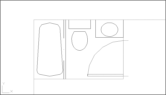
1. Zoom in to the bathroom so that the entire bathroom and part of the area around it are displayed, as shown in
Figure 6-21.
2. Select Wall from the layer drop-down list in the Layers panel to make Wall the current layer.
3. Make sure that the Object Snap Tracking and Object Snap tools on the status bar are turned on.
4. Click Line from the Draw panel, or type
L↵.
5. At the Specify first point: prompt, hover your cursor over the lower-right corner of the bathroom so that the Endpoint Osnap marker appears, but don’t click it.
6. Now move the cursor downward and, as you do, the tracking vector appears. (If the tracking vector doesn’t appear at first, hover your cursor over the corner again until it does appear.)
Remember that a little cross appears at the osnap location, telling you that Osnap Tracking has “locked on” to that location.
7. With the tracking vector visible, point the cursor directly downward from the corner and then type 5↵. Metric users should type 13↵. A line starts 5′ (or 13 cm) below the lower-right corner of the bathroom.
8. Continue the line horizontally to the left to cross the left wall of the apartment unit slightly, as illustrated in the top image in
Figure 6-22. Press ↵.
9. Draw another line upward from the endpoint of the top door jamb to meet the top wall of the unit (see the bottom image in
Figure 6-22). Use the Perpendicular osnap to pick the top wall of the unit. This causes the line to end precisely on the wall line in perpendicular position, as seen in the bottom image in
Figure 6-22.
You can also use the Perpendicular osnap override to draw a line perpendicular to a nonorthogonal line—one at a 45° angle, for instance.
10. Draw a line connecting the two doorjambs. Then assign that line to the Ceiling layer. (See the top panel in
Figure 6-23.)
11. Draw a line 6′ down from the endpoint of the doorjamb nearest the corner. (See the top panel in
Figure 6-23.)
Smoothing the Arc
You may notice that some of the arcs in your bathroom drawing aren’t smooth. Don’t be alarmed; this is how AutoCAD displays arcs and circles in enlarged views. The arcs will be smooth when they’re plotted. If you want to see them now as they’re stored in the file, you can regenerate the drawing by typing RE↵ at the Command prompt. Chapter 7, “Mastering Viewing Tools, Hatches, and External References,” discusses regeneration in more detail.
In the previous exercise, Osnap Tracking mode enabled you to specify the starting point of a line at an exact distance from the corner of the bathroom. In step 7, you used the Direct Distance method for specifying distance and direction.
Selecting Points from a Known Location
Instead of using a tracking vector in step 6 of the previous exercise, you could choose From on the Osnap context menu and then open the context menu again and select Endpoint. Select the corner and enter a polar coordinate such as @5<–90 to accomplish the same task as this exercise.
Cleaning Up the Line Work
You’ve drawn some of the wall lines, approximating their endpoint locations. Next, you’ll use the Fillet command to join lines exactly end to end and then import the kitchen drawing.
Understanding the Osnap Tracking Vector
The Osnap Tracking vector comes into play only after you’ve placed an osnap marker on a location—in this case, the corner of the bathroom. It won’t appear at any other time. If you have both Running Osnaps and Osnap Tracking turned on, you’ll get the tracking vector every time the cursor lands on an osnap location. This can be confusing to novice users, so you may want to use Osnap Tracking sparingly until you become more comfortable with it.
Because Polar Tracking also uses a tracking vector, you may get the two confused. Remember that Polar Tracking lets you point the cursor in a specific direction while selecting points. If you’re an experienced AutoCAD user, you can think of it as a more intelligent Ortho mode. On the other hand, Osnap Tracking lets you align points to osnap locations. Experienced AutoCAD users can think of Osnap Tracking as a more intelligent XYZ filter option.
Follow these steps to join the lines:
1. Click the Fillet tool on the Modify panel or type
F↵.
The Fillet, Chamfer, and Blend Curves tools share the same location in the Modify toolbar, so the tool tip may say any of these. If it does, then click the flyout arrowhead next to the tool and select Fillet.
2. Type R↵0↵ to make sure the fillet radius is set to 0.
3. Fillet the two lines by picking the vertical and horizontal lines, as indicated in the bottom panel in
Figure 6-23 shown earlier in this chapter. Notice that these points lie on the portion of the line you want to keep. Your drawing will look like the bottom panel in
Figure 6-23.
Chamfer vs. Fillet vs. Blend Curves
The Chamfer command performs a similar function to the Fillet command, but unlike Fillet, it enables you to join two lines with an intermediate beveled line rather than with an arc. Chamfer can be set to join two lines at a corner in exactly the same manner as Fillet.
The Blend Curves command will also join lines, but it does so by inserting a curved spline to intuitively bridge a gap between the ends of various types of objects.
4. Fillet the bottom wall of the bathroom with the left wall of the unit, as shown in
Figure 6-24. Make sure the points you pick on the wall lines are on the side of the line you want to keep, not on the side you want trimmed.
5. Fillet the top wall of the unit with the right-side wall of the bathroom, as shown in
Figure 6-24.
You can select two lines at once for the fillet operation by using a crossing window; to do so, type C↵ at the Select first object or ...: prompt and then use a crossing window to select the two endpoints you want to join. The two endpoints closest to the fillet location are trimmed.
Where you select the lines affects the way the lines are joined. As you select objects to fillet, the side of the line where you click is the side that remains when the lines are joined. Figure 6-25 illustrates how the Fillet command works and shows what the Fillet options do.
If you select two parallel lines during the Fillet command, the two lines are joined with an arc.
Now import the kitchen plan you drew earlier in this chapter:
1. Click Insert on the Block panel and then, in the Insert dialog box, click the Browse button to locate the kitchen drawing you created earlier in this chapter. Make sure you leave the Specify On-Screen check box deselected under the Scale and Rotation groups of the Insert dialog box.
2. Place the kitchen drawing at the wall intersection below the bathtub. (See the top image in
Figure 6-26.)
If you didn’t complete the kitchen earlier in this chapter, you can insert the 06a-kitchen.dwg file. Metric users can insert 06 kitchen-metric.dwg.
3. Adjust your view with Pan and Zoom so that the upper portion of the apartment unit is centered in the drawing area, as illustrated in the top image in
Figure 6-26.
Placing the Door Accurately
The next step is to add the entry door shown in the bottom image in Figure 6-26. In doing that, you’ll use a number of new tools together to streamline the drawing process.
In this exercise, you’ll practice using the Osnap Tracking feature and the From Osnap option to place the entry door at an exact distance from the upper corner of the floor plan:
1. Right-click in the Command window, and choose Recent Commands ⇒ Insert from the context menu to open the Insert dialog box.
2. Select Door from the Name drop-down list.
3. Make sure the Specify On-Screen option is checked in the Rotation group but not in the Scale group, and then click OK. You’ll see the door follow the cursor in the drawing window.
4. Shift+right-click the mouse to open the Osnap context menu, and then choose From.
5. Make sure the Object Snap and Object Snap Tracking buttons on the status bar are on; then use the Endpoint Running Osnap to pick the corner where the upper-horizontal wall line meets the bathroom wall.
6. Move the cursor over the osnap marker so that the Osnap Tracking vector appears from the corner. Now move the cursor to the right, and you’ll see the Osnap Tracking vector extend from the corner.
7. Continue to move the cursor to the right so that the tracking vector readout shows roughly 6′, or 15 cm for metric users.
8. With the cursor in this position, enter 5↵. Metric users should enter 13↵. The door is placed exactly 5 (or 13) units to the right of the corner.
9. At the Specify rotation angle <0>: prompt, enter 270↵. Or, if you prefer, turn on Polar Tracking to orient the door so that it’s swinging into the studio. You’ve now accurately placed the entry door in the studio apartment.
10. Make sure the door is on the Door layer and the kitchen block is on the Fixture layer.
For a shortcut to setting an object’s layer, you can select the object or objects and then select a layer from the layer drop-down list in the Layers panel.
Next, add the finishing touches to the entry door:
1. Add 5′ (13 cm for metric users) doorjambs as shown in the bottom image in
Figure 6-26, and change their Layer property to the Jamb layer.
2. Choose the Break tool in the expanded Modify panel, and then select the header over the entry door. (See the bottom image in
Figure 6-26.)
3. Type F↵ to use the first-point option; then select the endpoint of one of the door jambs.
4. At the
Specify second break point: prompt, select the endpoint of the other jamb, as shown in the bottom image in
Figure 6-26. The line between the points disappears.
5. Draw the door header on the Ceiling layer, as shown in
Figure 6-27.
6. Click Offset on the Modify panel, and offset the top wall lines of the unit and the door header up 5′ (13 cm for metric users) so they connect with the top end of the doorjamb, as shown in
Figure 6-27. Don’t forget to include the short wall line from the door to the bathroom wall.
7. Choose Save As from the Application menu to save your file as Unit.
Using Polar and Osnap Tracking as Construction Line Tools
So far, you’ve been using existing geometry to place objects in the plan accurately. In this section, you’ll use the Polar and Osnap Tracking tools to extend the upper wall line 5′ (13 cm for metric users) beyond the right interior wall of the unit. You’ll also learn how to use the Construction Line tool to locate doorjambs accurately near the balcony.
Other Methods for Using the Break Command
In the exercise for finishing the unit plan, you used the Break command to place a gap in a line accurately over the entry door. In Chapter 5, you broke a line at a single point to create multiple, contiguous line segments.
In this chapter, you used the Break command’s first-point (F) option, which allows you to specify the first point of a break. You can also break a line without the F option, but with a little less accuracy. When you don’t use the F option, the point at which you select the object is used as the first breakpoint. If you’re in a hurry, you can dispense with the F option and place a gap in an approximate location. You can later use other tools to adjust the gap.
In addition, you can use locations on other objects to select the first and second points of a break. For example, you might want to align an opening with another opening some distance away. After you’ve selected the line to break, you can then use the F option and select two points on the existing opening to define the first and second breakpoints. The breakpoints will align in an orthogonal direction to the selected points.
Start by changing the Polar Tracking setting to include a 45° angle:
1. Right-click the Polar Tracking button in the status bar at the bottom of the AutoCAD window, and choose Settings to open the Drafting Settings dialog box at the Polar Tracking tab (see
Figure 6-28).
2. Select 45 from the Increment Angle drop-down list in the Polar Angle Settings group.
3. In the Object Snap Tracking Settings group, make sure the Track Using All Polar Angle Settings option is selected and click OK.
You’re ready to extend the wall line. For this operation, you’ll use grip editing:
1. Click the wall line at the top of the plan and to the right of the door to select the line and expose its grips.
2. Click the Ortho Mode button in the status bar to turn on Ortho mode. This keeps the wall line straight as you edit it.
3. Click the rightmost grip of the line to make it hot.
4. Place the cursor on the upper-right corner of the plan until you see the Endpoint osnap marker; then move the cursor away from the corner at a 45° angle. The Osnap Tracking vector appears at a 45° angle. Notice the small
X that appears at the intersection of the Osnap Tracking vector and the line (see
Figure 6-29).
With the Osnap Tracking vector and the line intersecting, click the mouse button. The line changes to extend exactly 5 units beyond the vertical interior wall of the plan.
5. Press the Esc key twice to clear your selection. Then repeat steps 1 through 4 for the horizontal wall line to the left of the door to extend that line to the left corner (see
Figure 6-30).
6. Click Zoom All from the Zoom flyout on the Navigation bar, or type
Z↵
A↵ to view the entire drawing. It looks like
Figure 6-31.
With Polar Tracking set to 45° and Osnap Tracking turned on in a crowded drawing, you may find that you’re selecting points you don’t really want to select. Just remember that if a drawing becomes too crowded, you can turn off these options temporarily by clicking the Object Snap Tracking or Polar Tracking button in the status bar.
In this exercise, you used Polar Tracking and Ortho mode to position the two lines used for the exterior walls of the studio unit accurately. This shows how you can take advantage of existing geometry with a combination of tools in the status bar.
Now you’ll finish the balcony by adding a sliding-glass door and a rail. This time, you’ll use lines for construction as well as for parts of the drawing. First, you’ll add the doorjamb by drawing a construction line. A construction line is a line that has an infinite length, but unlike a ray, it extends in both directions. After drawing the construction line, you’ll use it to position the doorjambs quickly.
Follow these steps:
1. Zoom in to the balcony area, which is the smaller rectangle at the bottom of the drawing.
Click the Construction Line tool on the expanded Draw panel. You can also type
XL↵. You’ll see this prompt:
Specify a point or [Hor/Ver/Ang/Bisect/Offset]:
2. Type O↵ or select Offset from the command line.
3. At the Specify offset distance or [Through] <0″-5′>: prompt, type 4′↵. Metric users should type 122↵.
4. At the Select a line object: prompt, click the wall line at the right of the unit.
5. At the
Specify side to offset: prompt, click a point to the left of the wall to display the construction line. (See the top image of
Figure 6-32.)
6. At the
Select a line object: prompt, click the left wall line and then click to the right of the selected wall to create another construction line. Your drawing should look like the top image in
Figure 6-32.
Next, you’ll edit the construction lines to form the jambs.
7. Press the Esc key to exit the Xline command.
8. Click Trim on the Modify panel or type
Tr↵.
9. Select the construction lines and the two horizontal lines representing the wall between the unit and the balcony and press ↵. You can either use a crossing window or select each line individually. You’ve just selected the objects to trim.
You can also use the Fence selection option to select the lines to be trimmed.
10. Click the horizontal lines at any point between the two construction lines. Then click the construction lines above and below the horizontal lines to trim them. Your drawing looks like the bottom image in
Figure 6-32.
11. Assign the trimmed construction lines to the Jamb layer.
12. Add lines on the Ceiling layer to represent the door header.
13. Draw lines between the two jambs (on the Door layer) to indicate a sliding-glass door (see
Figure 6-33).
The wall facing the balcony is now complete. To finish the unit, you need to show a handrail and the corners of the balcony wall:
1. Offset the bottom line of the balcony 3′ toward the top of the drawing. Metric users should offset the line 7.6 units.
2. Create a new layer called F-rail, and assign this offset line to it.
3. Add a 5′ (13 cm for metric users) horizontal line to the lower corners of the balcony, as shown in
Figure 6-33.
4. Click the Set Base Point tool from the Home tab’s expanded Block panel to set the base point at the lower-left corner of the balcony at the location shown in
Figure 6-33.
5. Zoom back to the previous view. Your drawing should now look like
Figure 6-34.
6. Click Save from the Quick Access toolbar to save the drawing, and then close the file.
Your studio apartment unit plan is now complete. The exercises you’ve just completed demonstrate a typical set of operations you’ll perform while building your drawings. In fact, nearly 80 percent of what you’ll do in AutoCAD is represented here.
Now, to review the drawing process and to create a drawing you’ll use later, you’ll draw the apartment building’s lobby. As you follow the steps, refer to Figure 6-35.
The Construction Line Options
There is more to the Construction Line command than you’ve seen in the exercises in this chapter. Here is a list of the Construction Line options and their uses:
Hor Draws horizontal construction lines as you click points.
Ver Draws vertical construction lines as you click points.
Ang Draws construction lines at a specified angle as you pick points.
Bisect Draws construction lines bisecting an angle or an area between two points.
Offset Draws construction lines offset at a specified distance from an existing line.
As is usual in floor plans, the elevator shaft is indicated by the box with the large X through it, and the stair shaft is indicated by the box with the row of parallel lines through it. If you’re in a hurry, use the finished version of this file, called Lobby.dwg (Lobby-metric.dwg for metric users).
To draw the apartment building lobby, follow these steps:
1. Create a new file called Lobby, using the Unit file as a prototype. (Open the Unit file, choose Save As from the Application menu, and enter Lobby for the new filename.)
2. Erase the entire unit (click the Erase tool from the Modify panel, and then type All↵↵).
3. Draw the three main rectangles that represent the outlines of the stair shaft, the elevator shaft, and the lobby.
4. To draw the stairs, copy or offset the stair shaft’s left wall to the right a distance of 4′ (122 cm). This creates the first line representing the steps.
5. Array this line in one row of 10 columns, using an 11′ (28 cm) column offset.
6. Draw the center line dividing the two flights of stairs.
7. Draw the elevator, insert the door, and assign the door to the Door layer. Practice using construction lines here.
8. Draw the doorjambs. Edit the door openings to add the door jambs and headers and add the interior walls to the stairwell.
9. Use the Base command to set the base point of the drawing. Your plan should resemble the one in
Figure 6-35, step 4.
10. Save the Lobby file and close it.
Using Rays
If you like the Construction Line tool but you would like to have one endpoint, you can use a ray (click Ray in the expanded Draw panel). A ray is like a line that starts from a point you select and continues off to an infinite distance. You specify the start point and angle of the ray. You can place a ray at the corner at a 45° angle and then fillet the ray to the horizontal wall line to shorten or lengthen the line to the appropriate length.
Finding an Exact Distance along a Curve
To find an exact distance along a curve or to mark off specific distance increments along a curve, do the following:
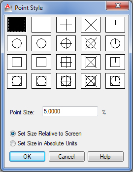
1. With a file open, click the Point Style tool in the Home tab’s expanded Utilities panel, or enter
ddptype↵ to open the Point Style dialog box (
Figure 6-36).
2. Click the X icon in the top row. Also be sure the Set Size Relative To Screen radio button is selected. Then click OK.
You can also set the point style by setting the Pdmode system variable to 3.
3. Click Measure from the expanded Draw panel, or type
ME↵ (see
Figure 6-37).
The Difference Between Divide and Measure
The Divide tool (Divide from the expanded Draw panel) marks off a line, an arc, or a curve into equal divisions as opposed to divisions of a length you specify. You might use Divide to divide an object into 12 equal segments, for example. Aside from this difference in function, Divide works exactly the same as Measure.
4. At the Select object to measure: prompt, click the end of the curve that you want to use as the starting point for your distance measurement.
5. At the
Specify length of segment or [Block]: prompt, enter the distance you want. A series of
Xs appears on the curve, marking off the specified distance along the curve. You can select the exact location of the
Xs by using the Node osnap override (see
Figure 6-38).
Using Blocks Instead of Points
The Block option of the Measure command enables you to specify a block to be inserted at the specified segment length in place of point objects on the arc. You can align the block with the arc as it’s inserted. Or you can use the Arraypath command described earlier in this chapter.
The Measure command also works on most objects, including arcs and polylines. You’ll get a more detailed look at the Measure command in Chapter 19.
As you work with AutoCAD, you’ll find that constructing temporary geometry such as the circle and points in the two previous examples will help you solve problems in new ways. Don’t hesitate to experiment! Remember, you’ve always got the Save and Undo commands to help you recover from mistakes.
Divide and Measure as AutoLISP Customization Tools
Divide and Measure are great tools for gathering information about objects in a drawing. A colleague of ours found it to be an excellent way to find the length of a complex object while working on an AutoLISP® macro. In AutoLISP, you have to write some elaborate code just to find the length of a complex polyline. After struggling with his program code, our colleague realized that he could use the Measure command to mark off known distances along a polyline and then count the points to find the overall length of the polyline.
Changing the Length of Objects
Suppose that, after finding the length of an arc, you realize you need to lengthen the arc by a specific amount. The Lengthen tool in the expanded Modify panel lets you lengthen or shorten arcs, lines, polylines, splines, and elliptical arcs. As an example, here’s how to lengthen an arc:
1. Click Lengthen from the expanded Modify panel, or type
LEN↵.
2. At the Select an object or [DElta/Percent/Total/DYnamic]: prompt, type T↵, or select Total from the command line.
3. At the Specify total length or [Angle] <1.0000)>: prompt, enter the length you want for the arc.
4. At the Select an object to change or [Undo]: prompt, click the arc you want to change. Be sure to click at a point nearest the end you want to lengthen. The arc increases in length to the size you specified.
The Lengthen command also shortens an object if it’s currently longer than the value you enter.
In this short example, you’ve learned how to change an object to a specific length. You can use other criteria to change an object’s length using these options available for the Lengthen command:
Delta Lengthens or shortens an object by a specific length. To specify an angle rather than a length, use the Angle suboption.
Percent Increases or decreases the length of an object by a percentage of its current length.
Total Specifies the total length or angle of an object.
Dynamic Lets you graphically change the length of an object using your cursor.
Creating a New Drawing by Using Parts from Another Drawing
Next, we’ll explain how to use the Export command. Export can be used to turn parts of a drawing into a separate file in a way similar to the Wblock command described in Chapter 4. Here you’ll use the Export command to create a separate staircase drawing by using the staircase you’ve already drawn for the lobby.
Follow these steps:
1. If you closed the Lobby file, open it now. If you didn’t create the lobby drawing, open the 06 Lobby.dwg (or 06 Lobby-metric.dwg) file.
2. Chose Export ⇒ Other Formats from the Application menu, or type export↵ to open the Export Data dialog box.
3. Enter stair.dwg in the File Name text box, and click Save. By including the .dwg filename extension, you let AutoCAD know that you want to export to a drawing file and not a file in some other file format, such as DXF or WMF.
4. At the Enter name of existing block or [= (block=output file)/* (whole drawing)] <define new drawing>: prompt, press ↵. When you export to a DWG format, AutoCAD assumes you want to export a block. Bypassing this prompt by pressing ↵ tells AutoCAD that you want to create a file from part of the drawing rather than from a block.
5. At the Specify insertion base point: prompt, pick the lower-right corner of the stair shaft. This tells AutoCAD the base point for the new drawing.
6. At the
Select objects: prompt, use a standard window (not a crossing window) to select the stair shaft, as shown in
Figure 6-39.
7. When the stair shaft, including the door, is highlighted, press ↵ to confirm your selection. The stairs disappear.
8. Because you want the stairs to remain in the lobby drawing, click the Undo button to bring them back. Undo doesn’t affect any files you might export by choosing Export ⇒ Other Formats from the Application menu, by using Wblock, or by using the Block tool.
Eliminating Unused Blocks, Layers, Linetypes, Shapes, Styles, and More
A template can contain blocks and layers you don’t need in your new file. For example, the lobby you just completed contains the bathroom block because you used the Unit file as a prototype. Even though you erased this block, it remains in the drawing file’s database. It’s considered unused because it doesn’t appear as part of the drawing. Such extra blocks can slow you down by increasing the amount of time needed to open the file. They also increase the size of your file unnecessarily. You can eliminate unused elements from a drawing by using the Purge command.
Selectively Removing Unused Elements
You use the Purge command to remove unused individual blocks, layers, linetypes, shapes, text styles, and other drawing elements from a drawing file. To help keep the file size small and to make layer maintenance easier, you should purge your drawing of unused elements. Bear in mind, however, that the Purge command doesn’t delete certain primary drawing elements—namely, layer 0, the Continuous linetype, and the Standard text style.
Use these steps to practice using the Purge command:
1. In the lobby drawing, choose Drawing Utilities ⇒ Purge from the Application menu to open the Purge dialog box (see
Figure 6-40). You’ll see a listing of drawing components that can be purged. If the drawing contains any of the types of components listed, a plus sign appears to the left of the component name.
2. Click the plus sign of the component you want to purge. In this exercise, click the plus sign next to the Blocks listing. The list expands to show the names of the items under the component category.
3. Select the name BATH from the expanded list. If you want to select more than one item, you can Ctrl+click individual names or Shift+click to select a group of names.
4. After the components are selected, click the Purge button in the lower-left corner of the dialog box. You then see a message box asking you to confirm that you want to purge the block.
5. Click Purge This Item and then click Close to close the Purge dialog box.
Removing All Unused Elements
In the previous exercise, you selected a single block for removal from the Lobby file. If you want to clear all the unused elements from a file at once, you can click the Purge All button at the bottom of the Purge dialog box (see Figure 6-40).
Here are the steps:
1. Choose Drawing Utilities ⇒ Purge from the Application menu to open the Purge dialog box again.
2. Click the Purge Nested Items check box to turn on this option.
3. Click Purge All to open the Confirm Purge dialog box, which asks whether you want to purge a block.
4. Click Purge This Item. The Confirm Purge dialog box displays the name of another block, asking you to confirm the purge. You can continue to click Purge This Item, and AutoCAD will display the Confirm Purge dialog box for each unused element still in the drawing.
5. Click the Purge All Items option to purge everything at once. The Confirm Purge dialog box closes.
6. In the Purge dialog box, click Close.
7. Close and save the Lobby file, and exit AutoCAD.
The Lobby file is now trimmed down to the essential data it needs and nothing else. You may have noticed that when you returned to the Purge dialog box in step 6, the items in the list box no longer showed plus signs. This indicates that there are no longer any unused items in the drawing.
In this last exercise, you used the Purge Nested Items option at the bottom of the dialog box. The Purge Nested Items option automatically purges unused blocks, including those nested within other blocks. If this option isn’t checked, you might have to repeat the Purge operation to remove all unused elements in a drawing.
Purging Zero-Length Geometry and Blank Text
At the very bottom of the Purge dialog box, you’ll see an option to “Purge zero-length geometry and empty text objects.” This has long been on the wish list of AutoCAD users, and it does just what it says: It purges objects that have no length as well as text objects that do not contain any text. They are offered in the Purge dialog box because they cannot be selected and deleted like normal AutoCAD objects.
The Bottom Line
Create and use templates. If you find that you’re using the same settings when you create a new drawing file, you can set up an existing file the way you like and save it as a template. You can then use your saved template for any new drawings you create.
Master It Describe the method for saving a file as a template.
Copy an object multiple times. Many tools in AutoCAD allow you to create multiple copies. The Array command offers a way to create circular copies, row and column copies, and copies that follow a path.
Master It What names are given to the three types of arrays offered in the Modify panel?
Develop your drawing. When laying down simple line work, you’ll use a few tools frequently. The exercises in the early part of this book showed you some of these commonly used tools.
Master It What tool can you use to join two lines end to end?
Find an exact distance along a curve. AutoCAD offers some tools that allow you to find an exact distance along a curve.
Master It Name the two tools you can use to mark off exact distances along a curve.
Change the length of objects. You can accurately adjust the length of a line or arc in AutoCAD using a single command.
Master It What is the keyboard alias for the command that changes the length of objects?
Create a new drawing by using parts from another drawing. You can save a lot of time by reusing parts of drawings. The Export command can help.
Master It True or false: The Export command saves only blocks as drawing files.