
Installing MSCS
Identifying all of the names of the cluster components, types of networks to configure, and values the network requires (IP addresses) ahead of time will make your installation process go very cleanly (and be repeatable). Also be sure to have the proper hardware in place beforehand. To provide complete documentation for this installation process, you should create a small Excel spreadsheet that contains these values and that organizes (groups) the information to correspond to the MSCS clustering configuration setup process (as shown in Figure 4.3). (This small Excel spreadsheet will also be available for download at the Sams website.) Figure 4.3 depicts the needed values and names for a typical 2-node cluster installation.
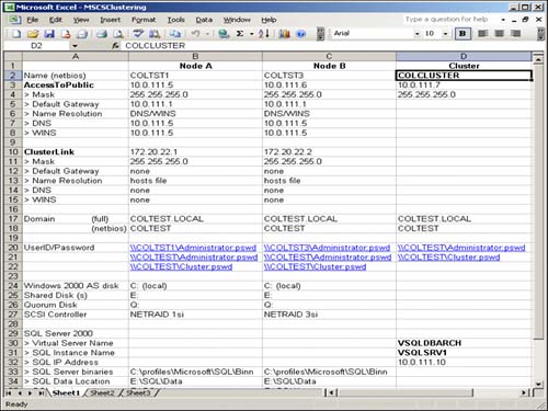
Basically, all of the cluster components for each node and for the cluster itself are listed in the spreadsheet. Your values will vary depending on server naming conventions, IP address and domain name availability, and user ID conventions. Once you have specified all values in this spreadsheet, you will find it very easy to walk through the MSCS installation wizard for each node in your cluster. You should always start with the first active server in your cluster. We will assume that your system admin has
Already built the physical servers (to specification)
Intalled Windows 2000 Advanced Server (or Datacenter) on each node
Named each physical server (like COLTST1 and COLTST3)
Identified (or defined) a domain for the node to be a member of (like the domain COLTEST) or configured all nodes to be domain controllers
Created a domain account that will be used by cluster services (like a domain account of “cluster”)
Formatted both the local SCSI drive (where the OS lives) and the shared SCSI disks with NTFS
Identified a pool of IP addresses to be used by MSCS
Pre-installation
Before you start the MSCS installation, take the time to fill out the MSCS clustering Excel spreadsheet (as seen in Figure 4.3) in its entirety. All prompts and questions in the MSCS Setup Wizard can then be taken directly from this spreadsheet.
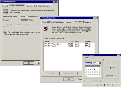
Figure 4.4 shows the system properties of our first server (COLTST1), its full computer name as it is known in our COLTEST domain (coltst1.coltest.local), the user account profiles that are set up for this computer (COLTESTAdministrator and COLTESTCluster), and the system date and time. The time turns out to be pretty important because each node in a cluster has to have its date and time synchronized. Once a node joins a cluster, its time will be automatically synchronized with the other nodes, but if the date/time is out of kilter to start with, a system error (event) will be encountered and a clustering configuration error will occur.
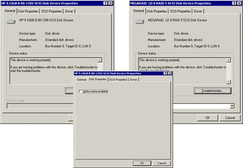
In addition, you should take a quick look at the local disk devices that will contain the operating system and the shared disk devices that will contain the application, which is easily done via the SCSI device properties. As you can see in Figure 4.5, both the local and shared SCSI drives are working properly (both the MEGARAID SCSI device and the HP SCSI device). If there are problems with the shared SCSI drives, they will show up here. Please note that the write cache enabled option has been disabled (clustering requires that this be turned off).
Installing MSCS—Step 1
In order to start installing MSCS, you must turn off all servers that will be in the cluster except the primary one (COLTST1 in this example) and the shared disk. Figure 4.6 illustrates the complete MSCS clustering topology for a two-node cluster on a Windows 2000 Advanced Server platform. This will be an active/passive cluster. We will use this clustering example for both the MSCS installation and for the SQL Server clustering installation (in Chapter 5, “Microsoft SQL Server Clustering”).
From the Configure Your Server menu (under Administrative tools), you will see the AdvancedCluster Service option down in the left corner of this menu. This initiates the MSCS wizard, as seen in Figure 4.7.
Figure 4.7. Initial MSCS Setup Wizard welcome.
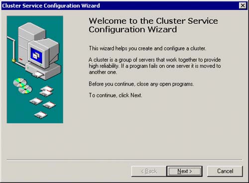
CAUTION If the OS install files for clustering are not preloaded on the hard drive, you'll need to have your Install CD handy before you'll see the Cluster Service Configuration Wizard welcome screen.
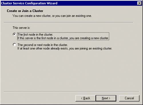
Once past the initial MSCS wizard dialog, you will be gently reminded to make sure you have validated your hardware against the Microsoft HCL (Hardware Compatibility List) that we discussed earlier. You are about to create a new cluster, since this is the first node in the cluster. When you are presented with the dialog box as seen in Figure 4.8, choose the First Node in the Cluster server option.
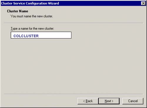
You will then have to name this new cluster. In Figure 4.9, we have named our sample cluster COLCLUSTER.
Figure 4.9. MSCS—Naming the cluster to be created.
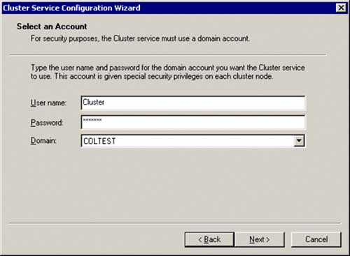
You will now be asked to identify a user name and domain which will be the domain account that you set up to use with this new cluster. In our example, we had identified a domain user account of Cluster for this purpose. Figure 4.10 shows the dialog box that specifies the user name, password and domain name to use for this new cluster. This domain user account will be given special security privileges on each node in the cluster.
Next you will identify the shared disks that are to be managed by the cluster. Any unmanaged disks not yet part of a cluster will be listed on the left side of this dialog. You must identify the ones you want by moving them to the right side (managed side) of this dialog box. Figure 4.11 shows the set of disks that are to be managed by this new cluster.
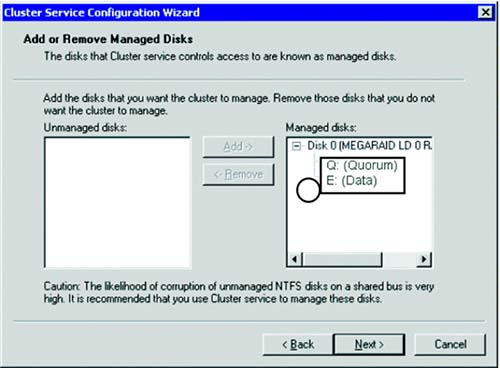
In this example, only one shared disk (RAID disk array) is going to be used. This shared disk has been partitioned into a Q: drive (for the quorum disk) and an E: drive (for application use). Once you have selected the disks to be managed by the cluster, you will have to specify the quorum disk location.
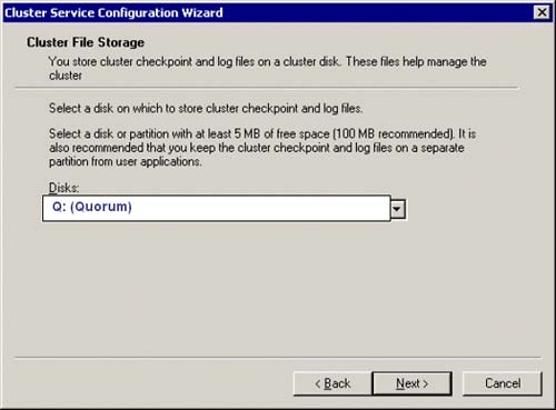
Remember, the quorum disk is where the cluster checkpoint and log files needed to manage the cluster are kept; this disk should be at least 100MB in size. Figure 4.12 shows the Q: Drive being selected for this purpose.
Figure 4.12. Identify the location of the quorum disk.
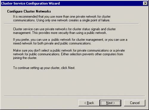
In our sample clustering topology, we will have only one private network for the cluster communication (to be named ClusterLink). The wizard will warn you that if you use only one private network for this internal heartbeat communication, you will have a single point of failure if that private network becomes unavailable. Use your discretion to create another, redundant network if you desire to minimize this point-of-failure even more. However, this is only a warning and you can proceed with the installation. Figure 4.13 shows the MSCS wizard dialog with this warning.
Figure 4.13. MSCS—private network warning.
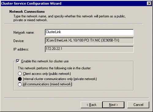
You now identify the private network that you want to use for the internal communication between the two nodes in the cluster. We have named this private network ClusterLink, as seen in Figure 4.14. Be sure to check the Enable this Network for Cluster Use box and specify that this network is to be for Internal Cluster Communication only (private network). We could have also chosen to use the All Communications (mixed network) option for this network connection role. Either role works (however, private network is recommended for this). You should also be able to see the device name of the network adapter (3Com EtherLink XL 10/100 PCI TX NIC (3C9058-TX)) that is dedicated to this private network along with the IP address (172.20.22.1 in this example) that is associated with this network adapter (you can manage IP addresses via the TCP/IP properties of the network adapter).
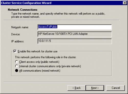
Next will be the specification of the public network that all client connections will use to access the server. A different device name (HP NetServer 10/100TX) will now appear in the dialog box along with its IP address (10.0.111.5). As you can see in Figure 4.15, you must specify a network name for this network connection, check the box to Enable this network for cluster use, and specify All communications (mixed network) role for this network connection. In our example, we have named the public network AccessToPublic. Okay, this is a bit boring, but it is also very clear as to its use.
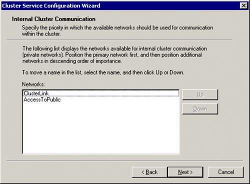
You must specify the internal order that you want the cluster manager to use for communicating across private networks. Remember, you have one network that is private only, and the other that is mixed mode (both public and private). For this reason, both networks should be listed here. This is an ordering specification, so make sure that the private only network is at the top of this list (from top to bottom). In Figure 4.16, our private network named ClusterLink has been moved to be first in line to be used by the cluster manager for internal communication.
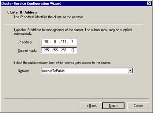
Now the magic happens: The next dialog box is the place where you specify the cluster IP address (for our cluster named COLCLUSTER). This IP address will be what the cluster is known by for use by any application that is cluster aware (like SQL Server) instead of a physical network address that is tied to a specific network adapter. In fact, as you can see in Figure 4.17, you will also specify a subnet mask and the public network name from which clients (applications) will gain access to the cluster. If we look to our MSCS spreadsheet, we see that we want the cluster COLCLUSTER to have the IP address of 10.0.111.7; we will take the default subnet mask of 255.255.255.0, and specify the AccessToPublic network name for the public network access for the cluster. This is the software/hardware glue point that masks the physical network adapter addresses from the logical cluster address.
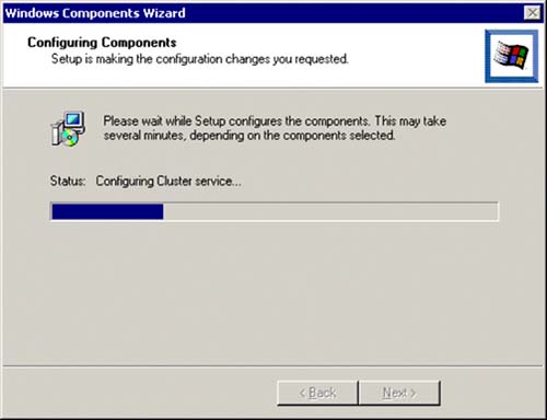
Now, the Windows Components Wizard will finish the cluster configuration. Several things are being done here, such as setting up a cluster service (in services), enabling the cluster network communication, and creating a cluster administrator account (to manage the cluster), as seen in Figure 4.18.
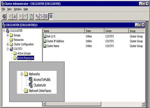
Once this is complete, the cluster administrator can be invoked to view or change the cluster configuration. It is now an available program group on your server. In Chapter 5, we will explore more of the capabilities of managing a cluster with the cluster manager. Figure 4.19 shows how the cluster administrator displays the new cluster we just created (COLCLUSTER). If you click on Cluster Resources and expand Networks (as you can see in the box in the left corner of Figure 4.19), both of the networks that are being used by the cluster will be listed (which we just defined).
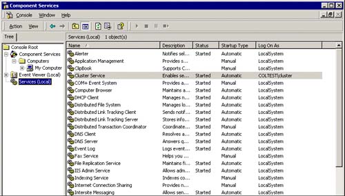
As you can see in Figure 4.20, a Cluster Service that is logged in as COLTESTcluster is added to your local server (COLTST1) and is set to automatically start each time the server is booted.
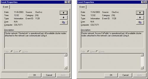
When the cluster service is started, several system event messages are generated that provide you with the status of the cluster itself. Figure 4.21 shows an example of event ID 1128 that shows the status of the cluster networks (our private network named ClusterLink and our public network named AccessToPublic). In this example, both are operational and all available cluster nodes can communicate using them. It is also here where you will see problems (errors). In debugging a failed cluster, I always start here first.
Figure 4.21. MSCS event properties for the private network named “ClusterLink” (dialog box on the left) and event properties for the public network named “AccessToPublic” (dialog box on the right).
Okay, all has gone smoothly in this configuration and now it is time to configure the other node in our two-node cluster.
Installing MSCS for the Next Node: Step 2
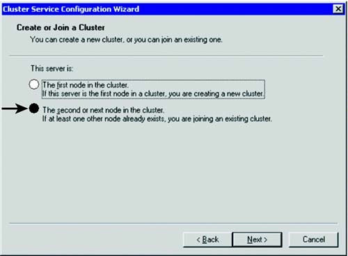
Repeat the same process for the second node in the cluster (and all subsequent nodes if more than two nodes are being set up). You must have the first node up and running and the shared disk available (and connected to this second node). From that new node, as you can see in Figure 4.22, instead of creating a new cluster, you will simply join an existing one by specifying that this server is “The second or next node in the cluster.”
Once the second node is created, both cluster nodes will appear in the Cluster Administrator, as seen in Figure 4.23.
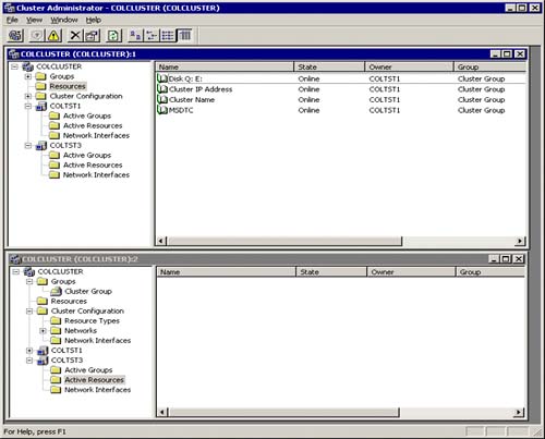
You can see both servers in the cluster administrator (COLTST1 and COLTST3). Currently, COLTST1 is the active server (owns the resources). COLTST3's resources are empty. You can also see these resources are online.
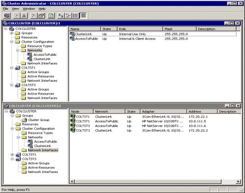
If you click on the Network Interfaces program groups under the Cluster Configuration group, you will see all the details associated with the network and the defined interfaces, including the specified network names, state (UP or DOWN), the network adapters being used, and the IP addresses. See Figure 4.24.
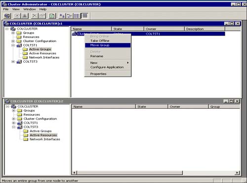
You can easily test a failover from COLTST1 to COLTST3 by right-clicking on COLTST1's Active Groups program group and choosing the Move Group option. By default, as shown in Figure 4.25, this will take the resources for this cluster group offline from COLTST1 and bring them online to COLTST3.
Congratulations, you have successfully installed and tested a two-node cluster.
Extending Clustering with Network Load Balancing (NLB)
A second clustering technology, called network load balancing (NLB), is used to make sure a server is always available to handle requests. NLB works by spreading incoming client requests among a number of servers that are linked together to support a particular application. A typical example is to use NLB to process incoming visitors to your website. As more visitors come to your site, you can incrementally increase capacity by adding servers. This type of expansion is often referred to as software scaling or scaling out. Figure 4.26 illustrates this extended clustering architecture with NLB.
Using both MSCS and NLB clustering technologies together, you can create an n-tier infrastructure. For instance, create an n-tiered e-commerce application by deploying NLB across a front-end web server farm and use MSCS clustering on the back-end for your line-of-business applications such as clustering your SQL Server databases. This gives you the benefits of near-linear scalability without server or application-based single points of failure. This, combined with industry-standard best practices for designing high-availability networking infrastructures, can ensure your Windows 2000[en]based, Internet-enabled business will be online all the time and can quickly scale to meet demand. There are other tiers that could be added to the topology, such as an application center tier that uses component load balancing (CLB). This further extends the clustering and scalability reach for candidate applications that can benefit from this type of architecture.