
CHAPTER 3
Azure Stack Architecture
IN THIS CHAPTER
![]() Overview of Azure Stack Integrated System
Overview of Azure Stack Integrated System
![]() Azure Stack Architecture Overview
Azure Stack Architecture Overview
This chapter explores how Azure Stack architecture is designed to support a single Azure ecosystem. It provides a comprehensive overview of Azure Stack’s integrated system design. The chapter also includes an in-depth review of the design, focusing on Azure Stack’s three main pillars of compute, storage, and networking, and provides information on Azure Stack deployment planning and data center integration points.
Overview of Azure Stack Integrated System
An Azure Stack integrated system is a collection of software that is available in Azure, a set of tested hardware systems that supports Azure fabric, a set of support infrastructure with solutions from Microsoft and its original equipment manufacturer (OEM) partners, and a set of services such as rack and stack, placement, deployment, and so on, that builds up a full hybrid cloud ecosystem. Figure 3.1 shows the lifecycle of the Azure Stack Integrated System, explained as follows:
![]() Architecture, hardware, and topology: Azure Stack’s underlying hardware and software is OEM hardware from Dell, HP, Lenovo, and Cisco (with announcements from Huawei and Avanade for availability in 2018); Windows Server 2016; Storage Spaces Direct (S2D); software-defined networking (SDN); and so on. This combination delivers the performance, scale, and performance of Azure in your data center.
Architecture, hardware, and topology: Azure Stack’s underlying hardware and software is OEM hardware from Dell, HP, Lenovo, and Cisco (with announcements from Huawei and Avanade for availability in 2018); Windows Server 2016; Storage Spaces Direct (S2D); software-defined networking (SDN); and so on. This combination delivers the performance, scale, and performance of Azure in your data center.
![]() Deployment, configuration, provisioning: Microsoft works closely with OEM partners such as Dell, HP, Lenovo, Cisco, Avanade and Huawei to understand how customers want to deploy services in their data centers, ensuring that the company can accommodate a variety of environments and configurations.
Deployment, configuration, provisioning: Microsoft works closely with OEM partners such as Dell, HP, Lenovo, Cisco, Avanade and Huawei to understand how customers want to deploy services in their data centers, ensuring that the company can accommodate a variety of environments and configurations.
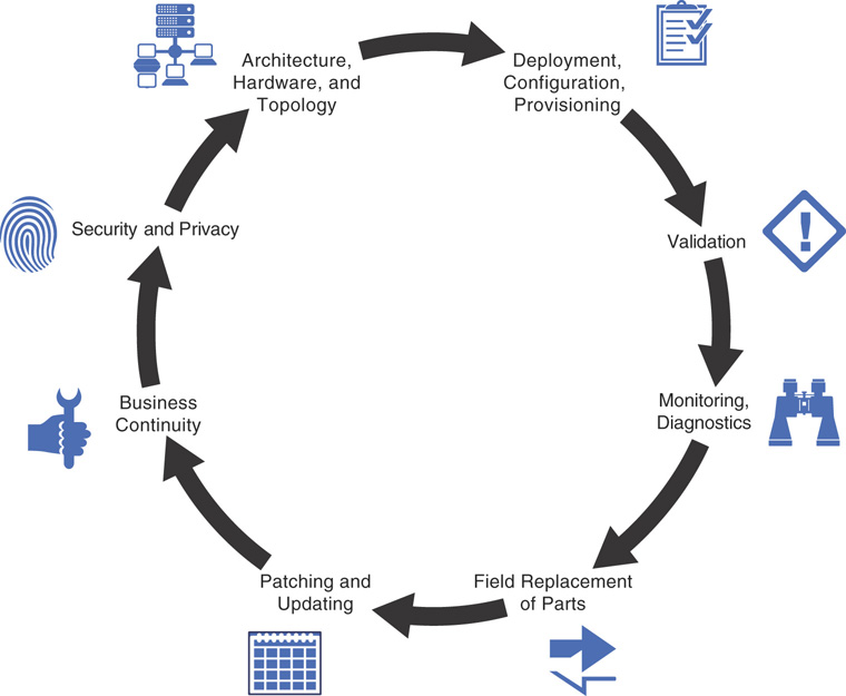
![]() Validation: Validation is an integral phase where software and hardware are tested to ensure the right features and functions are delivered in the host bus adapter (HBA), network interface cards (NICs), servers, storage devices, and network switches that comprise Azure Stack, so that when you deploy Azure Stack these components are not only individually tested but also validated as an entire solution.
Validation: Validation is an integral phase where software and hardware are tested to ensure the right features and functions are delivered in the host bus adapter (HBA), network interface cards (NICs), servers, storage devices, and network switches that comprise Azure Stack, so that when you deploy Azure Stack these components are not only individually tested but also validated as an entire solution.
![]() Monitoring and diagnostics: Maintaining a large system like Azure Stack requires that you understand what’s going on under the hood, what’s operationally functional, what proactive and reactive measures to perform for optimal performance, and how to integrate those diagnostics with your existing environment.
Monitoring and diagnostics: Maintaining a large system like Azure Stack requires that you understand what’s going on under the hood, what’s operationally functional, what proactive and reactive measures to perform for optimal performance, and how to integrate those diagnostics with your existing environment.
![]() Field replacement of parts: As hardware and software will fail at some point, Azure Stack should be able to accommodate that eventuality. Microsoft and its OEM partners have their own supply chain cycles and support infrastructure, brought together to satisfy the overall service level agreed upon with customers in the event of a system failure.
Field replacement of parts: As hardware and software will fail at some point, Azure Stack should be able to accommodate that eventuality. Microsoft and its OEM partners have their own supply chain cycles and support infrastructure, brought together to satisfy the overall service level agreed upon with customers in the event of a system failure.
![]() Patching and updating: As Microsoft delivers software updates on a regular cadence in Azure, it is essential to have equivalent and consistent updates in Azure Stack as well. This includes providing services, security patches, firmware updates, and so on, in a way that is non-disruptive to the workloads running on top of Azure Stack.
Patching and updating: As Microsoft delivers software updates on a regular cadence in Azure, it is essential to have equivalent and consistent updates in Azure Stack as well. This includes providing services, security patches, firmware updates, and so on, in a way that is non-disruptive to the workloads running on top of Azure Stack.
![]() Business continuity: Disasters of any form can impact an organization’s business, making it critical to have proper measures to ensure business continuity. Backup and disaster recovery options integrated in Azure Stack guarantee that your regular data center operations can avert a business outage in the event of such a disaster.
Business continuity: Disasters of any form can impact an organization’s business, making it critical to have proper measures to ensure business continuity. Backup and disaster recovery options integrated in Azure Stack guarantee that your regular data center operations can avert a business outage in the event of such a disaster.
![]() Security and privacy: Your deployment, management, and configuration of Azure Stack should meet the security requirements of your business, service delivery partners, and other stakeholders to ensure that the platform is secured against all threats.
Security and privacy: Your deployment, management, and configuration of Azure Stack should meet the security requirements of your business, service delivery partners, and other stakeholders to ensure that the platform is secured against all threats.
Each of these elements is essential for optimal performance in Azure Stack, which is consistent with Azure lifecycle management and thereby provides a unified management experience.
Azure Stack Architecture Overview
Microsoft Azure Stack allows you to implement the services and embrace the power of Microsoft Azure in your own data center using certified hardware. The underlying platform and fabric of Azure Stack are similar to that of Microsoft Azure. Microsoft Azure is a massive cloud platform consisting of 36 data centers worldwide along with hundreds and thousands of servers running across those data centers to provide next generation cloud platform capabilities. While your organization might not need such a large data center capacity as a service provider or an enterprise, Azure Stack lets you provide core Azure services to your customers or organizations, starting as small as a 4-node compute cluster hosting Azure Stack in a production deployment. The “Defining an Installation or Instance of Azure Stack” section of this chapter provides an overview of how to organize Azure Stack into instances.
Figure 3.2 is a detailed architecture diagram of Azure Stack at a very high level from an operational standpoint.
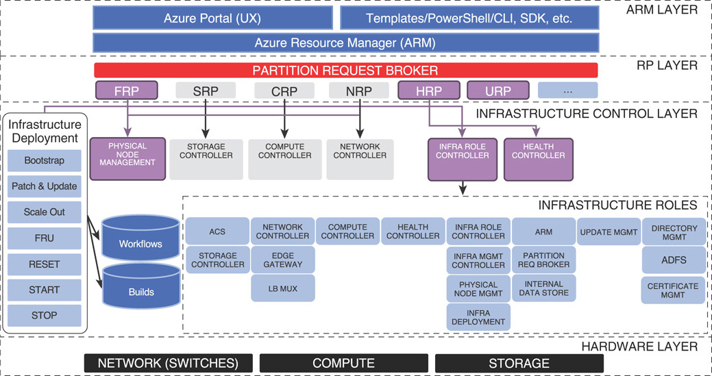
Azure Stack is consistent with Azure as it provides the same management experience of the Azure portal, service deployment via Azure Resource Manager (ARM) templates, PowerShell, and Azure command-line interface (CLI) and application development using the Azure software development kit (SDK). Azure Resource Manager is an instance that runs in Azure Stack and is your interaction point in Azure Stack both as tenant and administrator.
The partition request broker is basically a set of core resource providers in Azure Stack and is an application programming interface (API) that works back and forth with the ARM layer. A resource provider is what allows you to communicate with underlying resources, and includes a user extension that allows you to utilize it from the portal. Each resource provider has a north-bound interface that plugs into Azure Resource Manager, and a south-bound interface that communicates with the underlying infrastructure.
Infrastructure deployment is an automation engine in Azure Resource Manager that is included as a part of Azure Stack. It performs the actual deployment, automation, and updates in Azure Stack. Finally, infrastructure roles contain all the management components of Azure Stack, interacting with the underlying hardware layer to abstract hardware features into high-level software services that Azure Stack provides.
Defining an Installation or Instance of Azure Stack
An installation or an instance of Azure Stack can be defined in many ways. Essentially, it is a single instance of Azure Resource Manager with one or more regions under management of ARM, one or more scale units within a region, and four or more servers within a scale unit. The next sections provide additional details.
Azure Stack Region
An Azure Stack region is a set of scale units that share the same physical location, and are under one physical and logical administrator. A region contains high bandwidth/low latency—flat, layer-3 network connectivity that serves as the communication link between Azure Stack scale units. Customers can organize scale units into regions depending on their requirements for planning those regions.
Azure Stack Scale Unit
An Azure Stack scale unit is always associated with a single region and is a unit of capacity expansion in Azure Stack. There can be one or more scale units within a region. Each scale unit can be composed of a different generation of hardware than the others (homogenous within the scale unit). A scale unit is also equivalent to a fault domain, which resembles a failover cluster within your Azure Stack region.
In a production deployment of Azure Stack, the smallest scale unit comprises four servers. A single scale unit supports up to 16 servers per scale. The scale of your deployment can be calculated using the following formula.
Scale = Number of servers per scale unit x Number of scale units per region x Number of regions
NOTE: GENERAL AVAILABILITY OF AZURE STACK
Azure Stack supports a single-region deployment as of today. A subsequent update, estimated to be available in early 2018, will introduce multi-region support for geo-redundancy and scale across regions in Azure Stack.
Designing an Azure Stack Scale Unit
A minimal installation of an Azure Stack deployment contains at least one scale unit. The smallest scale contains a minimum of four servers plus a set of network switches. Each server is installed from bare metal with Azure Stack and contains the following (minimum) hardware specification:
![]() 2 × 10Gb ports with remote direct memory access (RDMA)
2 × 10Gb ports with remote direct memory access (RDMA)
![]() 256GB Memory
256GB Memory
![]() 1 × boot media (400GB or larger with optional mirroring), 2 × SSD for cache (NVMe, SATA SSD or SAS SSD) + 4 × HDD for capacity (HDD or SSD)
1 × boot media (400GB or larger with optional mirroring), 2 × SSD for cache (NVMe, SATA SSD or SAS SSD) + 4 × HDD for capacity (HDD or SSD)
![]() 10 × cores per CPU, min 2 × CPUs
10 × cores per CPU, min 2 × CPUs
Figure 3.3 denotes several sample Azure Stack scale units from Microsoft OEM partners HPE, Dell, and Lenovo. Other partners include Cisco, with availability from Huawei and Avanade expected in 2018.
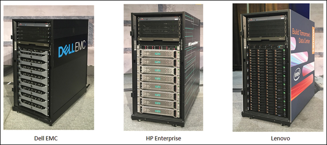
FIGURE 3.3 Azure Stack scale units from several OEM partners.
All servers are aggregated together in a hyper-converged failover cluster where the compute and storage layers are deployed in the same cluster. Azure Stack leverages Storage Spaces Direct, the software-defined storage sub-system that ships with Windows Server 2016. Every single component in Azure Stack is deployed in a resilient manner; the resiliency depends on that particular component. For example, the Azure Stack portal and ARM are web properties and therefore deployed behind a load balancer that is a built-in configurable server role in Windows Server 2016. All servers must share the same top-of-rack (ToR) switch (ToR pair), and more than one failover cluster per ToR pair can be included. Also, all servers within a single scale unit must be homogenously configured (that is, CPU, memory, NIC, and storage devices).
Figure 3.4 is a visual representation of Azure Stack integrated system architecture.
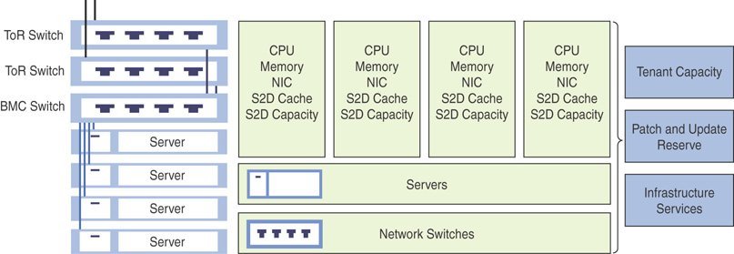
FIGURE 3.4 Azure Stack integrated system.
This architecture addresses smaller entry points for Azure Stack solutions and eases capacity expansion.
Azure Stack Internals
As with any enterprise computer system, Azure Stack also is a combination of three essential components: compute, storage, and network. By utilizing Windows Server 2016’s software-defined data center capabilities, Microsoft Azure Stack abstracts the hardware infrastructure into tenant-ready cloud services that are synonymous with Microsoft Azure.
Hardware Management in Azure Stack
Azure Stack leverages a set of controllers built on top of software-defined data center capabilities of Windows Server 2016 to manage the hardware system. Figure 3.5 summarizes the hardware management cycle of Azure Stack.
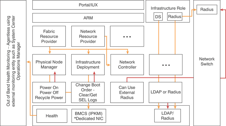
FIGURE 3.5 Azure Stack hardware management workflow.
Physical switches use remote authentication dial-in user service (RADIUS) authentication, which allows auditing capabilities (that is, who authenticated on a switch, whether that operation was successful or failed, and so on) in Azure Stack. Baseboard management controllers (BMCs) in Azure Stack support both lightweight directory access protocol (LDAP) and RADIUS authentication. Retrieving hardware-related health information is handled by out-of-band management tools; as Microsoft does not allow monitoring agents to be installed, all hardware-related health information is gathered using an intelligent platform management interface (IPMI) through the BMC. Additionally, the Health Resource Provider (HRP) gathers all hardware- and software-related health information and exposes those via an API.
Physical Node Management Controller (PNM)
Azure Stack interacts with the physical servers using the built-in BMCs such as HP iLO, Dell iDRAC, and so on. PNM uses a PcsvDevice leveraging IPMI implementation to communicate with the BMC. This allows the base operations depicted in Figure 3.6, enabling an Azure Stack administrator to recover a physical node at any given point in time. PNM authenticates using a BMC account or LDAP (recommended for larger scale), and securely stores BMC credentials.
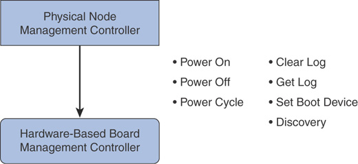
FIGURE 3.6 Azure Stack physical node management controller.
Infrastructure Role Controller
The infrastructure role controller (IRC) interacts with infrastructure roles in Azure Stack and performs lifecycle management as well. It uses Windows authentication to interact with hosting platforms (service fabric, failover clustering, Windows servers, Internet Information Services) of infrastructure roles, and IRC protocol is also based on the hosting platform.
Figure 3.7 is a visual representation of the Azure Stack infrastructure role controller.
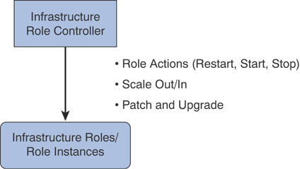
FIGURE 3.7 Azure Stack infrastructure role controller.
Compute Controller
The compute controller is leveraged both by Azure Stack infrastructure and the compute resource provider (CRP). It provides virtual machine (VM) lifecycle management in Azure Stack by interacting with the scale unit and Hyper-V to manage virtual machines. It uses a PowerShell implementation and authenticates using Just Enough Administration (JEA) principles in PowerShell.
Figure 3.8 is a visual representation of Azure Stack compute controller.
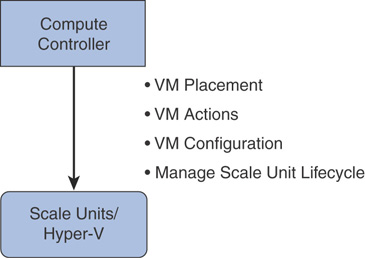
FIGURE 3.8 Azure Stack compute controller.
NOTE: ADDITIONAL CONTENT ON RESOURCE PROVIDERS
Infrastructure resource providers such as the Fabric Resource Provider (FRP), HRP, and Update Resource Provider (URP) are explained in detail in Chapter 5, “Using Resource Providers.”
Azure Stack Hardware Lifecycle Host
Azure Stack Hardware Lifecycle Host (HLH) is a server connected to a BMC network, which is external to the Azure Stack environment. This is a separate preinstalled physical server shipped with each scale unit. Azure Stack hardware vendors use the HLH to deliver their own lifecycle management software.
The server is connected to the BMC switch and contains Windows Server 2016 Standard or Datacenter edition. It is enabled with the Hyper-V role by default and designed to meet Azure Stack security requirements.
This server will host the hardware monitoring software (such as Dell OpenManage), perform firmware configuration and software updates (drivers), and enable emergency management and hardware monitoring. It will also be responsible for running the Azure Stack deployment virtual machine (DVM) during the initial Azure Stack deployment. The host contains the complete Azure Stack deployment media, including the generic Microsoft Azure Stack image and OEM extension packages such as OEM drivers, firmware, and software.
DVM is the starting point of an Azure Stack deployment and contains OEM drivers from the HLH. During initial setup it holds several roles including Active Directory Domain Services (ADDS), Windows Deployment Services (WDS), Dynamic Host Controller Protocol (DHCP), and so on. When the deployment of first physical nodes is complete, these roles are moved to those physical nodes.
Azure Stack Compute Overview
Azure Stack infrastructure as a service (IaaS) is the collection of foundational services on which all other platform as a service (PaaS) services build. IaaS resources in Azure Stack are provisioned and managed via Azure-consistent tools, such as the Azure Stack SDK and portal. IaaS cloud service design in Azure Stack builds on and extends the software-defined data center platform capabilities of Windows Server 2016.
As previously discussed in the “Designing an Azure Stack Scale Unit” section of this chapter, an Azure Stack instance physically starts at a minimum of four servers in a scale unit, which is a hyper-converged system by design. A server contains two CPUs (with a minimum of ten cores per CPU) and 256GB RAM at a minimum. All servers within a scale unit must have the same configuration, meaning you need to have the exact same hardware available inside a scale unit.
VM Sizes
A primary goal of Azure Stack is to provide consistency with Microsoft Azure. This consistency is achieved through fault domains, region concept, VM sizes, and so on. IaaS workloads in Azure Stack are able to leverage equivalent Azure VM SKUs. The VM sizes in Microsoft Azure vary; as Azure is a massive distributed system, not all VM SKUs available in the public cloud are available in a consumer deployment of Azure Stack—due to its limited capacity compared to Azure. Therefore, very small and large SKUs are unavailable and VM sizes in Azure Stack will be aligned to allow for mobility of templates, much like fault domains.
Future releases of Azure Stack will include additional VM sizes aligned with hardware specifications from OEM partners based on factors such as the most popular VM sizes and customer needs. At the time of writing of this book, Azure Stack supports the A, D, and Dv2 series of VM SKUs. Table 3.1 summarizes the available VM SKUs and their capacity limitations in Azure Stack.
TABLE 3.1 Azure Stack initial IaaS VM SKUs
Compute Resource Provider
The Azure Stack compute resource provider (CRP) is an infrastructure component that manages compute clusters and orchestrates creating IaaS VMs in Azure Stack. It leverages the code hardened in Azure and provides resiliency by running all services in a service fabric ring based on a microservice architecture.
Figure 3.9 demonstrates the high-level architecture of Azure Stack CRP.
VM Creation in Azure Stack
Tenant VM creation sequence in Azure Stack differs from classic Hyper-V VM creation. CRP’s virtual machine pipeline is a goal-seeking engine that exercises the full breadth of core services in Azure Stack. As Figure 3.9 shows, the compute controller performs VM placement, the storage resource provider (SRP) acquires the page blob for the VM, and the network resource provider (NRP) creates the NICs for the tenant VM. These foundational resource providers (CRP, NRP, and SRP) work together and communicate using their APIs to orchestrate VM creation—like solving a jigsaw puzzle, where each block integrates with another to solve the puzzle.
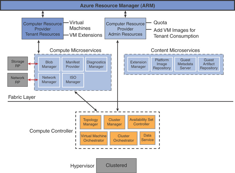
Figure 3.10 demonstrates how a virtual machine is created in Azure Stack.
VM Extensions
VM extensions in Azure Stack allow in-guest customization of a new or existing VM, deployed using the Azure Linux and Windows agents. The Azure Linux agent is preloaded into Linux VM images; Azure Stack requires the latest version. When you build your own custom images in Azure Stack, ensure that you have the latest VM agent installed in your custom image, based on its operating system (OS).
CRP exposes administrative user interfaces (UIs) and APIs to facilitate access to the VM image and extension repositories. This is the core functionality used to deliver marketplace syndication. Also, when you curate compute content for Azure Stack (that is, upload your own custom image to Azure Stack marketplace), you need to ensure that the dependencies included in the compute content in your Azure Stack deployment (extensions, custom content, and so on) do not restrict you from using that image in Azure.
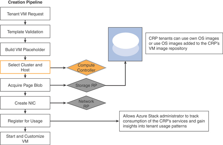
Figure 3.11 demonstrates how a virtual machine extension is deployed in Azure Stack.
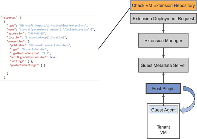
FIGURE 3.11 Deploying VM extensions in Azure Stack.
Azure Stack Storage Overview
Azure Stack storage uses Windows Server 2016 S2D to provide software-defined storage capabilities to tenant workloads. Azure Stack deploys S2D in a hyper-converged architecture, where both compute and storage subsystems reside in the same servers in which Azure Stack is deployed. S2D uses a cluster shared volume file system (CSVFS) with ReFS as the file system allowing cluster-wide data access, fast VHD(X) creation, expansion, and checkpoints; these enhance the performance and reliability of the storage system.
S2D allows you to create a software-defined storage system with a minimum of two to a maximum of sixteen servers, containing up to 400 drives in a single instance. A single S2D cluster can occupy over 3PB of raw storage and allows you to add servers to scale out and drives to scale up, with the S2D pool automatically absorbing new drives when they are added for capacity expansion. S2D offers better storage efficiency and performance at larger scale, and simplifies procuring storage in Azure Stack.
Storage Spaces Direct Architecture
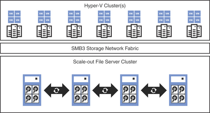
Figure 3.12 examines the underlying high-level architecture of S2D, described as follows. Note that option 1 denotes converged architecture, and option 2 denotes hyper-converged architecture, discussed in the next section.
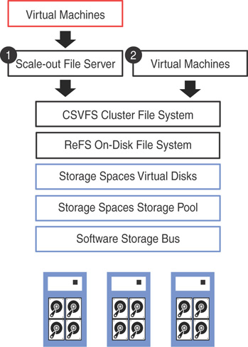
FIGURE 3.12 S2D architecture.
![]() Resilient File System (ReFS): This is a file system built to enhance the server virtualization experience in Windows Server. The accelerated VHDX operations feature in ReFS significantly improves the creation, expansion, and checkpoint merging in virtual disks. Cluster shared volumes (CSV) consolidate the ReFS volumes into a single namespace that you can access from any server, thus making it shared storage.
Resilient File System (ReFS): This is a file system built to enhance the server virtualization experience in Windows Server. The accelerated VHDX operations feature in ReFS significantly improves the creation, expansion, and checkpoint merging in virtual disks. Cluster shared volumes (CSV) consolidate the ReFS volumes into a single namespace that you can access from any server, thus making it shared storage.
![]() Scale-Out File Server (SOFS): If you have deployed a converged S2D solution, implementing SOFS is a must. A SOFS provides remote file access by leveraging the SMB3 protocol to clients. An example of this is a Hyper-V compute cluster. With a hyper-converged S2D deployment, both storage and compute is available in the same cluster, eliminating the need to deploy SOFS.
Scale-Out File Server (SOFS): If you have deployed a converged S2D solution, implementing SOFS is a must. A SOFS provides remote file access by leveraging the SMB3 protocol to clients. An example of this is a Hyper-V compute cluster. With a hyper-converged S2D deployment, both storage and compute is available in the same cluster, eliminating the need to deploy SOFS.
![]() Storage Spaces: These are deployed as a single scalable pool with all disk devices (except boot) and contain multiple virtual disks per pool (with mirroring or parity). There are three options for fault tolerance for virtual disks in S2D; mirroring, erasure coding, or mirroring + erasure coding. S2D is a distributed, software-defined redundant array of independent disks (RAID), using the drives in the pool. In S2D, these virtual disks usually are resilient to two simultaneous drive or server failures (using three-way mirroring, with each data copy in a different server), although chassis and rack fault tolerance is also available.
Storage Spaces: These are deployed as a single scalable pool with all disk devices (except boot) and contain multiple virtual disks per pool (with mirroring or parity). There are three options for fault tolerance for virtual disks in S2D; mirroring, erasure coding, or mirroring + erasure coding. S2D is a distributed, software-defined redundant array of independent disks (RAID), using the drives in the pool. In S2D, these virtual disks usually are resilient to two simultaneous drive or server failures (using three-way mirroring, with each data copy in a different server), although chassis and rack fault tolerance is also available.
![]() Software Storage Bus: The Software Storage Bus establishes a software-defined storage fabric that spans across the storage cluster. All servers in the cluster can see each other’s local drives. This replaces the need for expensive and restrictive fiber channel or shared SAS cabling. The Software Storage Bus leverages SMB3 and SMB Direct.
Software Storage Bus: The Software Storage Bus establishes a software-defined storage fabric that spans across the storage cluster. All servers in the cluster can see each other’s local drives. This replaces the need for expensive and restrictive fiber channel or shared SAS cabling. The Software Storage Bus leverages SMB3 and SMB Direct.
![]() Storage Bus Layer Cache: The storage bus layer cache is designed to dynamically bind the fastest drives in S2D to slower drives (for example, binding SSD to SATA HDDs). This provides server-side read/write caching to accelerate IO and boost throughput. The cache is integral to the software storage bus, and is scoped to the local machine. This is agnostic to a storage pool; virtual disks are automatically configured when enabling S2D.
Storage Bus Layer Cache: The storage bus layer cache is designed to dynamically bind the fastest drives in S2D to slower drives (for example, binding SSD to SATA HDDs). This provides server-side read/write caching to accelerate IO and boost throughput. The cache is integral to the software storage bus, and is scoped to the local machine. This is agnostic to a storage pool; virtual disks are automatically configured when enabling S2D.
![]() Physical disks: Physical disks in S2D can be a combination of SATA, SAS, and NVM Express (NVMe) SSD, and are locally attached to the Azure Stack servers.
Physical disks: Physical disks in S2D can be a combination of SATA, SAS, and NVM Express (NVMe) SSD, and are locally attached to the Azure Stack servers.
Storage Spaces Direct Deployment Options
There are two deployment options available with S2D:
![]() Converged: SOFS are built on top of a converged S2D deployment to provide shared storage using SMB3 file shares. This segregates the storage from compute, similar to traditional NAS/SAN systems, and is ideal for a large-scale enterprise deployment, such as Hyper-V VMs hosted by service providers. In this architecture, both compute and storage resources scale and are managed independently from each other. Figure 3.13 depicts S2D converged architecture in Azure Stack.
Converged: SOFS are built on top of a converged S2D deployment to provide shared storage using SMB3 file shares. This segregates the storage from compute, similar to traditional NAS/SAN systems, and is ideal for a large-scale enterprise deployment, such as Hyper-V VMs hosted by service providers. In this architecture, both compute and storage resources scale and are managed independently from each other. Figure 3.13 depicts S2D converged architecture in Azure Stack.
![]() Hyper-Converged: With hyper-converged deployments, both compute and storage layers are available in the same servers; this model allows further reduction of the hardware cost and is ideal for SMEs. In a hyper-converged architecture, both compute and storage resources scale and are managed together in a single system. This is the default deployment option for Azure Stack. Figure 3.14 shows S2D hyper-converged architecture in Azure Stack.
Hyper-Converged: With hyper-converged deployments, both compute and storage layers are available in the same servers; this model allows further reduction of the hardware cost and is ideal for SMEs. In a hyper-converged architecture, both compute and storage resources scale and are managed together in a single system. This is the default deployment option for Azure Stack. Figure 3.14 shows S2D hyper-converged architecture in Azure Stack.
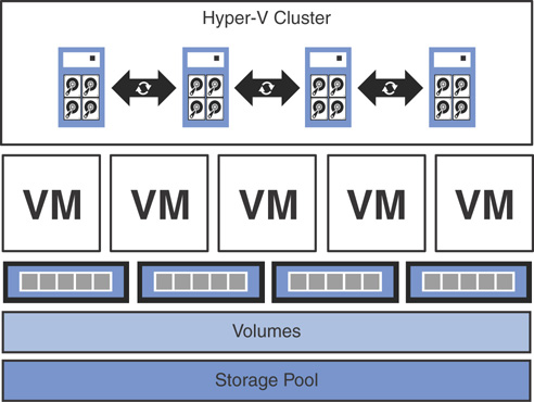
FIGURE 3.14 S2D hyper-converged architecture.
Azure-Consistent Storage Architecture
Azure-consistent storage is a set of storage cloud services that provides blob, table, queue, and account management features in Azure Stack. Azure-consistent storage provides the following functionalities:
![]() Blobs: Azure-consistent page blobs, block blobs, and append blobs
Blobs: Azure-consistent page blobs, block blobs, and append blobs
![]() Tables: Azure-consistent entities, partitions, and other table properties
Tables: Azure-consistent entities, partitions, and other table properties
![]() Queues: Reliable and persistent messages and queues that are compatible with Azure-consistent queue behavior
Queues: Reliable and persistent messages and queues that are compatible with Azure-consistent queue behavior
![]() Accounts: Azure-consistent storage account resource management for general-purpose storage accounts provisioned in the ARM deployment model
Accounts: Azure-consistent storage account resource management for general-purpose storage accounts provisioned in the ARM deployment model
![]() Administration: Management of tenant-facing and storage internal storage services that are Azure-consistent
Administration: Management of tenant-facing and storage internal storage services that are Azure-consistent
Figure 3.15 shows an overview of an Azure-consistent storage solution.
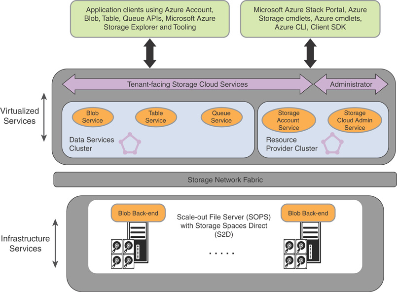
FIGURE 3.15 Azure-consistent storage: solution view.
The following describes the Azure Stack storage functionalities that leverage the Azure-consistent storage virtualized services and clusters:
![]() Blob service and software-defined storage
Blob service and software-defined storage
The Blob service runs on the back end, running directly on the SOFS cluster nodes. Azure Stack SOFS is based on the S2D-based, shared-nothing failover cluster. Figure 3.15 illustrates the major component services of the Azure-consistent storage solution in Azure Stack. Azure-consistent storage conforms with existing software-defined storage features in Windows Server 2016; therefore, no special hardware is required for Azure-consistent storage beyond these software-defined platform requirements.
![]() Storage farm
Storage farm
A storage farm is a collection of storage infrastructure, resources, and back-end services that together provide tenant-facing and administrator-facing Azure-consistent storage services in Azure Stack. It possesses all storage cloud service infrastructure in the region, including the following:
![]() Storage hardware (SOFS nodes, disks)
Storage hardware (SOFS nodes, disks)
![]() Storage fabric resources (SMB shares)
Storage fabric resources (SMB shares)
![]() Storage-related service fabric services (blob endpoint service off Azure-consistent storage cluster)
Storage-related service fabric services (blob endpoint service off Azure-consistent storage cluster)
![]() Storage-related services that run on a SOFS (blob service)
Storage-related services that run on a SOFS (blob service)
![]() Storage usage scenarios
Storage usage scenarios
As in Microsoft Azure, Azure-consistent storage page blobs provide the virtual disks for all IaaS usage scenarios in Azure Stack:
![]() Creating a VM based on a custom OS disk in a page blob
Creating a VM based on a custom OS disk in a page blob
![]() Creating a VM based on a custom OS image in a page blob
Creating a VM based on a custom OS image in a page blob
![]() Creating a VM based on an Azure Marketplace image in a new page blob
Creating a VM based on an Azure Marketplace image in a new page blob
![]()
![]() Creating a VM based on a blank disk in a new page blob
Creating a VM based on a blank disk in a new page blob
In Azure Stack PaaS services, storage block blobs, append blobs, queues, and tables behave in a similar manner as in Azure.
Azure Stack Networking Overview
Azure Stack network resource creation is consistent with Azure, as it brings the power of the new Microsoft software-defined networking stack to Azure Stack. Azure Stack SDN embraces industry standards like Virtual Extensible LAN (VXLAN) and Open vSwitch Database (OVSDB), and incorporates technologies directly from Azure such as the Software Load Balancer (SLB) and Virtual Filtering Platform (VFP) vSwitch extension that is proven to be reliable, robust, and scalable.
Azure Stack SDN leverages investments in Windows Server 2016 such as Packet Direct, Switch Embedded Teaming (SET), converged NIC, offloads, and many others to provide software-defined networking capabilities at cloud scale.
Physical Network Switch Topology
Azure Stack has two connectivity types:
![]() DATA: Windows Server 2016 Converged NIC : SDN + Storage
DATA: Windows Server 2016 Converged NIC : SDN + Storage
![]() BMC: Physical host control + third party hardware monitoring
BMC: Physical host control + third party hardware monitoring
The intent of this architecture is to provide data transport for both storage/tenant workloads and physical hosts in the form of BMC connections. This is important, as in Azure Stack you not only perform the initial deployment and control the individual servers but will also redeploy servers in the event of a failure. As an example, if the boot disk of a server fails, you would add a new server with a functioning boot disk and provide the BMC IP address in the Azure Stack administrator portal; Azure Stack would do the rest of the configuration itself.
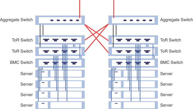
Resiliency is always adhered to while designing each infrastructure component in Azure Stack. In the network layer, resiliency is achieved by using redundant network interfaces (DATA – 10Gbps + single physical NIC with dual ports at a minimum), and on top of that using switch-embedded-teaming for port/link resiliency and building up a dual-switch (TOR) configuration from there.
As Figure 3.16 shows, each server is connected to both ToR switches and the BMC switch is connected to each of the ToR switches. The ToR switches are also inter-connected for resiliency. When you add another scale unit, you must have connectivity between scale units; this is achieved by adding another layer of switching, referred to as aggregated switches, on top of the scale unit. This entire mesh of network topology is known as a layer 3/flat L3 network. Once a packet travels northbound from the layer 2 level of ToR switches towards aggregated switches—that is, to another rack or outside the solution—it is travelling through a layer 3 network.
The following subnets are used in the Azure Stack host network:
![]() BMC
BMC
![]() Infrastructure
Infrastructure
![]() Storage
Storage
![]() External virtual IPs
External virtual IPs
Virtual IP Addressing
Figure 3.17 illustrates each arrow representing a set of virtual IP addresses (VIP) in Azure Stack. Each component in Azure Stack architecture has its own set of VIPs.
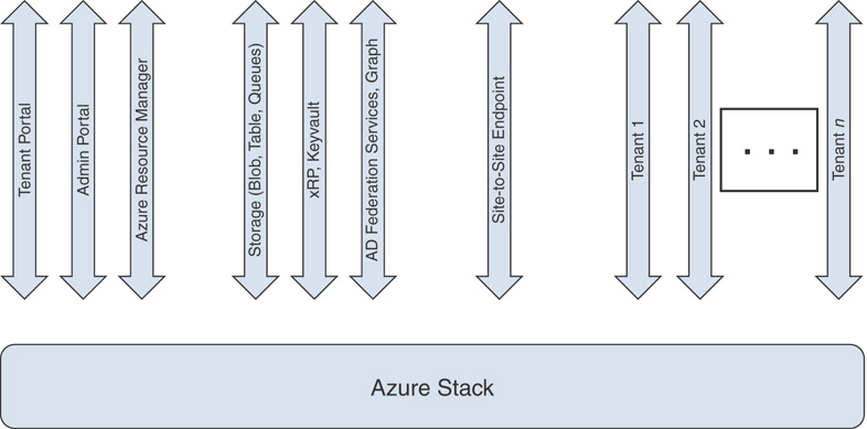
FIGURE 3.17 Azure Stack virtual IP addressing.
Hyper-V Network Virtualization (HNV) in Azure Stack
Figure 3.18 represents how inbound and outbound network traffic flows to the SDN layer of Azure Stack. The transit network interacts directly with the network switch, creating a BGP relationship and routing the traffic to the next hop end-point from the physical switch into the SDN stack. The traffic is then routed through the vSwitch up to the VMs, which are running the SDN infrastructure in Azure Stack. The SLB has VIP mappings to the tenant workloads and rewrites the network traffic to the designated tenant VMs.
Physical to Logical Switch Transition
Figure 3.19 depicts the network traffic transition from physical switch to logical switch. The SLB has a separate BGP instance with its own ASN number. From a physical switch standpoint, it is just another switch. When there are multiple scale units, present traffic should travel through the aggregated switches. If you lose an aggregate switch in the first scale unit, the routing comes in on the second one; Azure Stack should then be able to route through the whole infrastructure despite the failure. BGP is utilized in the figure in the second scale unit, through the TOR switch and SLB. The ASN number in both SLBs is the same, so to the physical topology, traffic travels through the same physical switch from a routing standpoint.
NOTE: NIC AND SWITCH REQUIREMENTS OF AZURE STACK
The NICs and switches in Azure Stack have the following features and capabilities:
![]() NIC:
NIC:
![]() 10+ GbE
10+ GbE
![]() Dual port NIC strongly preferred
Dual port NIC strongly preferred
![]() RDMA (iWARP or RoCEv2)
RDMA (iWARP or RoCEv2)
![]() Converged NIC features (that is, VMMQ, VMQ port, RDMA Mode 2)
Converged NIC features (that is, VMMQ, VMQ port, RDMA Mode 2)
![]() Switch:
Switch:
![]() BGP
BGP
![]() Data Center Bridging (DCB) with Enhanced Transmission Selection (ETS) and Priority-based Flow Control (PFC)
Data Center Bridging (DCB) with Enhanced Transmission Selection (ETS) and Priority-based Flow Control (PFC)
![]() Switch Independent Teaming used by host
Switch Independent Teaming used by host
Software-Defined Networking in Azure Stack
Azure Stack builds upon the Windows Server 2016 SDN implementation. By implementing SDN, you can configure both physical and virtual network devices. Core elements of Azure Stack SDN infrastructure include Hyper-V Virtual Switch, Hyper-V Network Virtualization, and RAS Gateway. Although the existing physical switches, routers, and other hardware devices can still be used independently, deeper integration can be achieved between the virtual network and the physical network in Azure Stack, as these devices are designed for compatibility with software-defined networking.
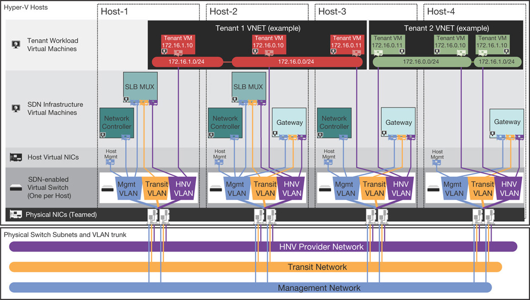
FIGURE 3.18 Azure Stack Hyper-V Network virtualization architecture.

FIGURE 3.19 Azure Stack physical-to-logical switch translation.
SDN implementation in Azure Stack is possible since the three network planes—the management, control, and data planes—are independent of the network devices themselves, but abstracted for use by other entities such as Azure Stack. SDN allows Azure Stack to dynamically manage its data center network to provide an automated, centralized mechanism to meet the requirements of the applications and workloads. SDN in Azure Stack provides the following capabilities:
![]() The ability to abstract applications and workloads from the underlying physical network, by virtualizing the network. Just as with server virtualization using Hyper-V, the abstractions are consistent and work with the applications and workloads in a non-disruptive manner. In fact, software-defined networking provides virtual abstractions for Azure Stack’s physical network elements, such as IP addresses, switches, and load balancers.
The ability to abstract applications and workloads from the underlying physical network, by virtualizing the network. Just as with server virtualization using Hyper-V, the abstractions are consistent and work with the applications and workloads in a non-disruptive manner. In fact, software-defined networking provides virtual abstractions for Azure Stack’s physical network elements, such as IP addresses, switches, and load balancers.
![]() The ability to centrally define and control policies that govern both physical and virtual networks, including traffic flow between these two network types.
The ability to centrally define and control policies that govern both physical and virtual networks, including traffic flow between these two network types.
![]() The ability to implement network policies in a consistent manner at scale, even as you deploy new workloads or move workloads across virtual or physical networks in Azure Stack.
The ability to implement network policies in a consistent manner at scale, even as you deploy new workloads or move workloads across virtual or physical networks in Azure Stack.
Figure 3.20 shows the high-level topology of Azure Stack SDN implementation.
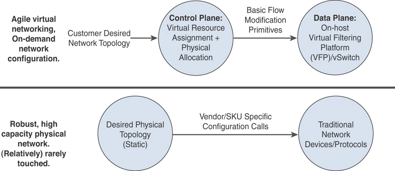
FIGURE 3.20 Azure Stack SDN implementation explained.
Figures 3.21 and 3.22 explain how the SDN architecture in Azure Stack is designed to provide hyper-scale networking capacities similar to Azure. In the management plane, ARM handles the authentication, authorization, and orchestration, and in turn communicates directly with the NRP. NRP, like other foundational resource providers in Azure Stack, is a web service that provides a foundation for all Azure-based IaaS and PaaS services. ARM relies on different resource providers to provide access to Azure Stack’s services.
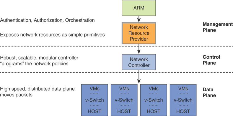
FIGURE 3.21 Azure Stack SDN high-level architecture.
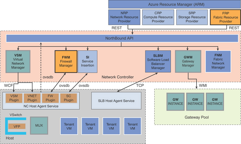
FIGURE 3.22 Azure Stack SDN detailed architecture.
The NRP possesses a series of SDN and network function virtualization (NFV) features to Azure Stack. These are consistent with Azure, enabling application templates to be written once and deployed both in Azure or Azure Stack. The network resource provider offers more granular network control, metadata tags, faster configuration, and rapid and repeatable customization. It also supports multiple control interfaces such as PowerShell, .NET SDK, Node.JS SDK, REST-based API, and so on.
The network controller resides in the control plane, and is designed with Azure in mind. It is a highly available and scalable server role, and provides an API that allows it to communicate with the Azure Stack network, and a second API that allows you to communicate with the network controller. The network controller communicates with the network layer using a south-bound API, which can discover, detect, and gather all information regarding network devices and services in the Azure Stack SDN implementation. The south-bound API also provides a channel to send information back to the physical network infrastructure, such as network configuration changes in Azure Stack.
The data plane, also known as the forwarding plane, is a set of hosts that perform the ground level traffic operations in SDN, such as forwarding the traffic to the next hop along the path to the selected destination network according to the control plane logic.
The network controller performs the bulk of the heavy operations in the SDN stack. SDN in Azure Stack is a componentized architecture, is not monolithic, and consists of a set of binaries and services that work together to build the SDN implementation in Azure Stack.
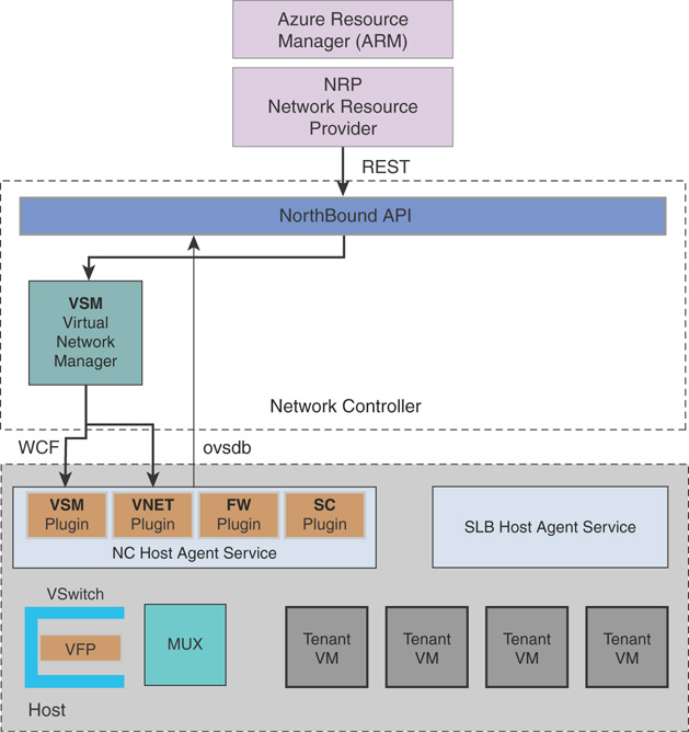
VNets in Azure Stack allow you to deploy your own network. They are completely isolated from one another, allowing you to create disjointed networks for development, testing, and production that all use the same CIDR address blocks. Using VNets, you can create subnets with your private or public IP address spaces.
By default, Internet access in a VNet is provided through NAT and does not require a gateway.
Another important consideration in VNets is how Azure Stack performs name resolution. Azure Stack has an internal DNS name resolution mechanism for instances deployed in tenant VNet. Tenants can also use their own DNS servers and configure the subsequent VNets to use with them. Security in VNets is provided through network security groups that control which traffic can enter or exit the tenant VNets.
VNets in Azure Stack support for VXLAN or NVGRE encapsulation formats (VXLAN is the default), and the Virtual Network Manager module in the network controller manages CA/PA mappings. Packet processing occurs on the Azure Stack host(s).
Figure 3.23 explains the communication flow of an Azure Stack VNET.
Software Load Balancer (SLB)
In Azure Stack, SLB performs the duties of a layer 4 load balancer and balances multiple network requests among hosts via a VIP. It also load balances among one or more VM instances and allows port redirection, SLB control traffic to endpoints with inbound NAT rules, and provides outbound (NAT) connectivity to the Internet while providing high availability for workloads with failover.
SLB maps VIPs to dynamic IP addresses (DIPs). VIPs are single IP addresses providing public access to a pool of load-balanced VMs. These IP addresses can be exposed on the Internet so Azure Stack service providers and tenants can connect to available resources.
DIPs are the IP addresses of the VMs of a load-balanced pool behind a VIP. They are assigned within the cloud infrastructure to tenant resources. VIPs are in the SLB multiplexer (MUX). The MUX consists of one or more VMs and the network controller provides each MUX with a VIP. Each MUX uses border gateway protocol (BGP) to advertise each VIP to routers on the physical network as a /32 route.
Figure 3.24 displays the communication flow of an Azure Stack software load balancer.
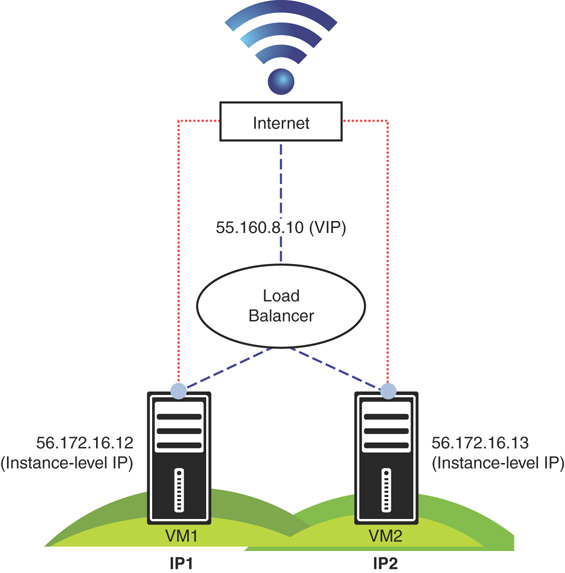
FIGURE 3.24 Azure Stack SLB architecture.
Virtual Network Gateways
The implementation of virtual network gateways in Azure Stack is slightly different from that of Azure. The SDN capabilities of Windows Server 2016 allow Azure Stack to provide virtual network gateway capabilities in Azure while the underlying infrastructure is scaled down into a much smaller set.
Gateways in Azure Stack are designed to allow cross-premise connectivity capacities such as site-to-site (S2S) VPN. Azure Stack leverages the multi-tenant gateway capabilities of Windows Server 2016 and provides high availability through an M+N model (active/passive).
A gateway manager balances load across gateway instances, monitors health, and handles failover in the event any active instance fails.
Figure 3.25 shows the network traffic flow from a virtual network gateway to the virtual NIC of a virtual machine in Azure Stack.
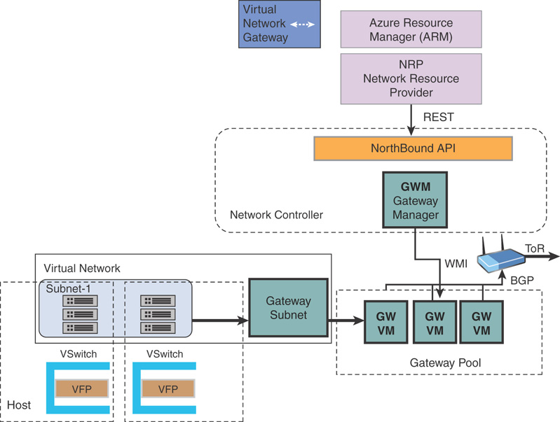
FIGURE 3.25 Azure Stack gateway architecture.
iDNS
iDNS in Azure Stack allows you to resolve external DNS names (such as http://www.google.com). It also allows you to register internal virtual network names. This lets you resolve VMs on the same virtual network by name, rather than IP address, without having to provide custom DNS server entries.
iDNS in Azure Stack can provide the following, without needing to specify custom DNS server entries:
![]() Shared DNS name resolution services for tenant workloads.
Shared DNS name resolution services for tenant workloads.
![]() Authoritative DNS service for name resolution and DNS registration within the tenant virtual network.
Authoritative DNS service for name resolution and DNS registration within the tenant virtual network.
![]() Recursive DNS service for resolution of Internet names from tenant VMs. Tenants no longer need to specify custom DNS entries to resolve Internet names (for example, www.google.com).
Recursive DNS service for resolution of Internet names from tenant VMs. Tenants no longer need to specify custom DNS entries to resolve Internet names (for example, www.google.com).
You can always use your own DNS and use custom DNS servers if required. However, if you just want to resolve Internet DNS names and to connect to other virtual machines in the same virtual network, there is no need to specify anything in the network configuration and resolution will just work using iDNS.
NOTE: DNS resolution in Azure Stack
iDNS cannot create a DNS record for a name that can be resolved from outside the virtual network. Azure provides the option of specifying a DNS name label that can be associated with a public IP address. You can choose the label (prefix), but Azure chooses the suffix, which is based on the region where you created the public IP address. This is not possible in Azure Stack at the time of writing this book.
Planning an Azure Stack Deployment
There are a number of items to consider when planning an Azure Stack implementation. Following are some points you should consider at a high level:
![]() Scale: If your intent is to deploy Azure Stack for production workloads, consider the size of your deployment. This involves having multiple regions and multiple scale units per region if your enterprise workloads span several geographically distributed data centers in your organization.
Scale: If your intent is to deploy Azure Stack for production workloads, consider the size of your deployment. This involves having multiple regions and multiple scale units per region if your enterprise workloads span several geographically distributed data centers in your organization.
![]() Purpose: As discussed earlier in the “Designing an Azure Stack Scale Unit” section of this chapter, Azure Stack is an integrated system provided by Microsoft OEM partners, starting at a minimum of four servers in a scale unit. However, if you are using Azure Stack for evaluation and dev/test workloads, you can always deploy an Azure Stack Development Kit on a single box with reduced capacity and functionality. Microsoft will continue to ship preview builds for the Azure Stack Development Kit, so customers can test the new features before updating production Azure Stack systems.
Purpose: As discussed earlier in the “Designing an Azure Stack Scale Unit” section of this chapter, Azure Stack is an integrated system provided by Microsoft OEM partners, starting at a minimum of four servers in a scale unit. However, if you are using Azure Stack for evaluation and dev/test workloads, you can always deploy an Azure Stack Development Kit on a single box with reduced capacity and functionality. Microsoft will continue to ship preview builds for the Azure Stack Development Kit, so customers can test the new features before updating production Azure Stack systems.
![]() Capacity: The IaaS instance offering in your Azure Stack deployment depends on the capacity of your integrated system. Factors such as the Azure VM sizes you want and the Azure Services you will offer and their requirements will determine the VM SKUs in production deployments. While future releases of Azure Stack may bring heavy VM SKUs to the hybrid platform, unless your data center can provide the underlying capacity needed, it would be useless to provision such SKUs without the required compute, storage, and network power.
Capacity: The IaaS instance offering in your Azure Stack deployment depends on the capacity of your integrated system. Factors such as the Azure VM sizes you want and the Azure Services you will offer and their requirements will determine the VM SKUs in production deployments. While future releases of Azure Stack may bring heavy VM SKUs to the hybrid platform, unless your data center can provide the underlying capacity needed, it would be useless to provision such SKUs without the required compute, storage, and network power.
![]() Workloads: The workloads in your enterprise can be either IO-intensive, CPU-intensive, or memory-intensive. In Azure Stack, IO-intensive workloads require more flash devices as storage, CPU-intensive workloads demand higher bin CPUs in a scale unit, and memory-intensive workloads demand optimal VM density in each host.
Workloads: The workloads in your enterprise can be either IO-intensive, CPU-intensive, or memory-intensive. In Azure Stack, IO-intensive workloads require more flash devices as storage, CPU-intensive workloads demand higher bin CPUs in a scale unit, and memory-intensive workloads demand optimal VM density in each host.
![]() Identity: Azure Stack leverages Azure Active Directory (AAD) or Active Directory Federation Services (ADFS) as its authentication mechanism. Multiple instances of AAD can be integrated to provide authentication for tenant services in Azure Stack. You also need to consider factors such as federated identity, self-service user management, and so on, to provide a robust end-user experience for your tenants.
Identity: Azure Stack leverages Azure Active Directory (AAD) or Active Directory Federation Services (ADFS) as its authentication mechanism. Multiple instances of AAD can be integrated to provide authentication for tenant services in Azure Stack. You also need to consider factors such as federated identity, self-service user management, and so on, to provide a robust end-user experience for your tenants.
Data Center Integration
Deploying Azure Stack in your data center involves a number of tasks and processes. As with any enterprise system, Azure Stack requires a regular cadence of lifecycle management. The following looks at the different integration points you should consider while deploying and running Azure Stack in your data center.
Figure 3.26 is a high-level deployment diagram of an Azure Stack deployment with n number of scale units.
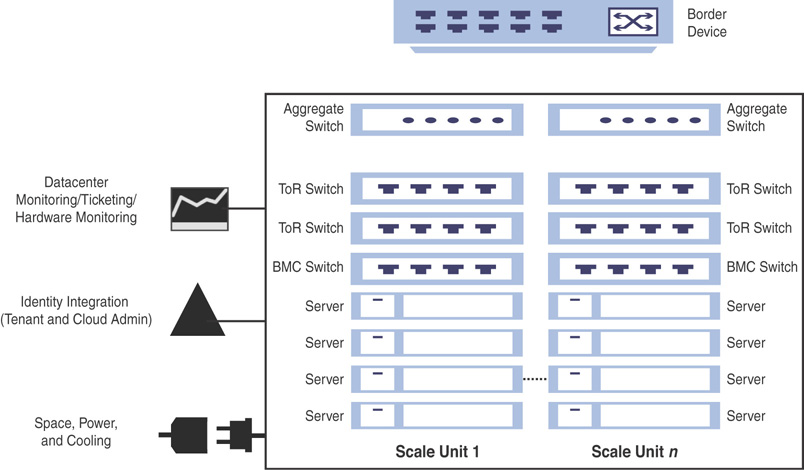
FIGURE 3.26 Deploying Azure Stack in your data center.
![]() Deployment: Configuring Azure Stack in your data center involves certain manual and automated tasks. As Azure Stack is delivered as an integrated system you will not be setting up any hardware on your own; instead, you will purchase a deployment-ready rack-and-stack scale unit from one of the Microsoft OEM partners, ready to plug into your data center. You still must manually configure network switches and integrate with the border network on the network stack, in collaboration with your Azure Stack OEM partner. If you have a large deployment, you may need to consider these requirements for other scale units of your Azure Stack instance as well. When you power on your Azure Stack system, one of the very first configuration tasks would be to establish connectivity with AAD or ADFS, and so on.
Deployment: Configuring Azure Stack in your data center involves certain manual and automated tasks. As Azure Stack is delivered as an integrated system you will not be setting up any hardware on your own; instead, you will purchase a deployment-ready rack-and-stack scale unit from one of the Microsoft OEM partners, ready to plug into your data center. You still must manually configure network switches and integrate with the border network on the network stack, in collaboration with your Azure Stack OEM partner. If you have a large deployment, you may need to consider these requirements for other scale units of your Azure Stack instance as well. When you power on your Azure Stack system, one of the very first configuration tasks would be to establish connectivity with AAD or ADFS, and so on.
![]() Validation: Azure Stack is validated as an integrated system, where all components are tested together to perform a complete system validation. Configuration of hardware components such as NICs, HBAs, drives, network switches, servers, and so on will follow the traditional Windows Server tests with the Windows hardware kit lab (HLK). Furthermore, there will be additional tests and diagnostics run specific to Azure Stack integration on top of the HLK.
Validation: Azure Stack is validated as an integrated system, where all components are tested together to perform a complete system validation. Configuration of hardware components such as NICs, HBAs, drives, network switches, servers, and so on will follow the traditional Windows Server tests with the Windows hardware kit lab (HLK). Furthermore, there will be additional tests and diagnostics run specific to Azure Stack integration on top of the HLK.
![]() Patching and Update: Patching and updating involves applying pre-validated updates for software and firmware by Microsoft and hardware partners. This automated application of updates across the entire infrastructure is designed to not disrupt tenant workloads. Unlike Windows Server updates, Azure Stack updates are delivered as one package that contain updates for hardware, OS, and software. The updates will be delivered at a rapid cadence, letting you choose when to apply them within a given time frame depending on their business requirements. Should you not deploy an update before the given time frame, the scale unit will go out of support. This ensures that patching and updating in Azure Stack will always be reliable, single-sourced, and easy to use.
Patching and Update: Patching and updating involves applying pre-validated updates for software and firmware by Microsoft and hardware partners. This automated application of updates across the entire infrastructure is designed to not disrupt tenant workloads. Unlike Windows Server updates, Azure Stack updates are delivered as one package that contain updates for hardware, OS, and software. The updates will be delivered at a rapid cadence, letting you choose when to apply them within a given time frame depending on their business requirements. Should you not deploy an update before the given time frame, the scale unit will go out of support. This ensures that patching and updating in Azure Stack will always be reliable, single-sourced, and easy to use.
![]() Monitoring and Service Management: The health state in Azure Stack is linked to alerts, and separates the health of cloud services from the cloud infrastructure. There are two types of health checks in Azure Stack:
Monitoring and Service Management: The health state in Azure Stack is linked to alerts, and separates the health of cloud services from the cloud infrastructure. There are two types of health checks in Azure Stack:
![]() Each component has its own notion of health and self-reports its own health status.
Each component has its own notion of health and self-reports its own health status.
![]() External system health tests that check how each component is used by the other components in Azure Stack.
External system health tests that check how each component is used by the other components in Azure Stack.
Based on these two types, alerts will be generated based on the health status; these are actionable alerts that link to online troubleshooting guides for systematic guidance.
Figure 3.27 provides a high-level overview of how monitoring is enabled in Azure Stack.
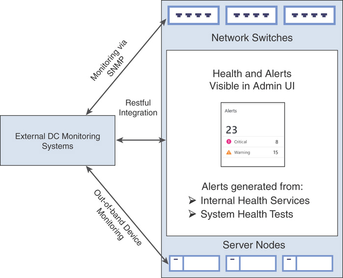
FIGURE 3.27 Monitoring Azure Stack.
As per your organizational requirements, you will also need to integrate Azure Stack with your existing monitoring systems. While Azure Stack does not allow you to install any monitoring agents, you can use existing connections from its own monitoring system such as Rest API, BMC, and SNMP to integrate with your existing monitoring solution and an information technology service management (ITSM) system.
Summary
Azure Stack is delivered as a pre-validated integrated system. It contains a complete infrastructure management system that fully integrates into your environment. Azure Stack IaaS is the collection of foundational services on which all other PaaS services build, and IaaS resources in Azure Stack are provisioned and managed via Azure-consistent tools, the SDK, and a portal. IaaS cloud service design in Azure Stack builds on and extends the software-defined data center (SDDC) platform capabilities of Windows Server 2016. This chapter focused on how Azure Stack architecture is designed to provide the capabilities of Microsoft Azure on-premise, running Azure in your data center environments as an integrated system.
Chapter 4, “Installing and Configuring Azure Stack,” explores the installation of the Azure Stack Development Kit and configuring an Azure Stack integrated system in a production environment. It provides information and context on how to verify and troubleshoot an Azure Stack installation, along with a complete overview of system specifications of an Azure Stack production system.