In this chapter we will introduce the topic of runbook design and the foundational components that Microsoft System Center Orchestrator 2012 provides for creating runbooks. The more familiar you are with all of the properties, behavior, and functionality of these building block components, the more efficiently you will be able to build runbooks to automate your IT processes. This section is similar to the process a developer must go through when learning a new development language. Developers learn the capabilities of all the statements and commands while also learning how to implement basic programming and algorithmic concepts such as looping and branching.
A runbook is a set of activities performed in a particular order to achieve a goal such as automating a particular IT process. The concept of a runbook dates to the early days of information technology and typically took the form of written documentation of IT processes and procedures for administering complex systems such as mainframes. The intent was the same as it is today: predictable and repeatable administration of IT systems in a structured way, not dependent on the knowledge of a particular individual or improvisation. Most large outages begin as small outages which are then compounded by administrators rushing to try to restore services as quickly as possible. Standard procedures for routine activities which are tested and refined over time greatly reduce the odds of human error. Runbooks in document form proved successful and the next logical step was to use scripting, management tools, and now orchestration tools to further automated processes.
In Orchestrator 2012, runbooks can range from simple two- or three-step automated processes up to large integrated collections of dozens or more runbooks automating entire IT processes such as patching or disaster recovery.
While runbook design and testing is primarily targeted at IT professionals and does not require developer expertise, many of the concepts used in script and code development do apply. Examples include modular or service-oriented design, designing for test, creating reusable libraries, and so on. Before we get into advanced runbook design, we’ll cover the basics which are the key building blocks for more advanced scenarios.
Introduced in previous chapters, the Orchestrator Runbook Designer is the product’s defining feature. The Runbook Designer provides a Microsoft Visio or Visual Basic-like design surface for runbook authoring, as shown in Figure 4-1. The combination of a visual designer and a wide range of standard activities and integration packs provide an IT pro or infrastructure developer a much more approachable solution for runbook automation than pure scripting, which requires more of a developer background. Orchestrator enables quite powerful automation to be created without requiring code or scripting, while also enabling code and scripts to be used if needed in advanced scenarios. Once the boundaries of the built-in activities and integration packs are reached, runbooks can then include script code (such as Windows PowerShell) or more advanced scenarios (custom .NET integration packs).

Runbooks include a variety of properties such as name and description. Both can be critical in terms of version control. Runbook properties include scheduled execution, meaning the author can specify that on particular date/time intervals the runbook will be executed. The system time of the runbook server is utilized for scheduling.
Runbook permissions can be set by right-clicking the folder or specific runbook. By default, only users in the Orchestrator Users group have full access to runbooks. Additional access can be granted to users to run, start, stop, view, and change runbooks at either the folder level or the runbook level. Keep in mind the permissions to edit or start a runbook are separate from the permissions or security context a runbook executes under. A runbook executes in the security context of the Orchestrator runbook service service account or if using an integration pack, the account used in the integration pack connection to the target management system.
Activities are key Orchestrator components that perform an individual function such as copying a file, opening an SSH connection, or powering on a virtual machine. Multiple activities and the links between them are what comprise a runbook. Activities may get or set parameters and execute scripts or tasks, among many other possible actions.
The standard activities are those that are built into a default installation of Orchestrator. These activities tend to be “utility” activities such as file management, email, and runbook control activities. Most runbooks will use a variety of standard activities. The full list of standard activities is listed at http://technet.microsoft.com/en-us/library/hh403832.aspx.
Monitoring activities are activities which monitor for specific events or conditions and then begin execution of the runbook they are part of. Examples include monitoring a folder for the existence of a specific file, or the state of service on a target machine. A monitor activity, if utilized, must be the first activity in the runbook and any runbooks beginning with a monitor activity must be started in order for the monitoring to be in effect. These conditions have the following implications:
Since the runbook must be running in order for the monitor to be effective, it consumes one runbook of the maximum number of runbooks the server can execute, which is 50 by default (this can be configured higher if the server has the resources to execute more).
You need to ensure that upon runbook server reboots or other operations that all your runbooks with monitors are started (which itself is a great example of a problem that can be solved with a runbook, one which starts all of your other runbooks containing monitors).
A common use of a monitor activity is the Date/Time activity which monitors for specific dates, times, or intervals and executes the rest of the runbook. If you want to check the availability of a server every 15 minutes, you can create a runbook that starts with a Date/Time monitor set to fire every 15 minutes then run your activities to check the target server as a subsequent step.
Customized activities are those that are delivered as part of an Orchestrator integration pack (IP) such as the Microsoft-provided System Center integration pack or from custom objects and integration packs created using the Orchestrator Integration Toolkit (OIT). Use of the OIT is beyond the scope of this book, more information can be found here: http://msdn.microsoft.com/library/dd834977.aspx
Common activity properties are those that all Orchestrator activities contain. Examples include Name and Description under the General tab of the activity. Activities also have a Details tab which may include required properties or other fields. Finally, there is a Run Behavior tab which includes settings for Returned Data Behavior and event notification. The Returned Data Behavior settings are crucial to understand. An activity might return a large amount of data. Consider Query Database standard activity which might return 100 rows of data depending on the configured query. Two possible uses for the returned data are supported depending on the activity settings. You may want to execute a subsequent step on each row of data returned, which Orchestrator lets you do and is one of its most powerful features (parallel execution of multiple runbooks) or you may want to “flatten” the data, and pass all 100 rows of data to the next step as one large published data item. Orchestrator provides the option to return data “flattened” using the separator you specify (such as a comma).
Event Notification enables you to tell Orchestrator to log an application when an activity takes longer than a duration you specify to execute or if the activity fails. For instance, if the above database query example takes more than 60 seconds to execute, you could configure Orchestrator to log a notification event.
The workflow control activities within Orchestrator are the foundation that all runbooks are built from. Understanding the features and functionalities of the workflow control activities is important because a full understanding opens a wide range of new scenarios for building runbooks and systems of runbooks that work well together.
Starting point activities in Orchestrator are the activities which all runbooks must start with. A runbook can only have one starting point activity. Typically runbooks will utilize an Initialize Data activity or a Monitor activity as the starting point. The starting point activity begins when the runbook is started by a console operator, invoked by another runbook, or invoked via the Orchestrator web service. Monitoring activities were discussed previously. The Initialize Data activity is also commonly used as it provides the ability to specify input parameters for the runbook. Any parameters configured on the Initialize Data activity will be presented as input fields when the runbook is executed from the Orchestration Console. Input parameters are also available when the runbook is executed through the web service or when triggered from System Center Service Manager if the Orchestrator connector from Service Manager is configured. Examples of common input parameters include the computer name of the target system to be managed, a transaction identifier, and so on.
Links connect one activity to another in Orchestrator. Links include properties which allow you to establish conditional logic. An example is a link that only allows proceeding to the next activity if the previous activity was successful. Another example would be a link that only proceeds if the previous activity returned a specific value (that is, a success exit code from a script). An activity can have multiple links on its input side and/or multiple links on its output side. This capability enables a wide range of branching scenarios to support complex and multistep processes. The example in Figure 4-2 illustrates one activity that has multiple links on its output side resulting is several branches which may execute depending on the link conditions.
Activities can be configured with a loop so that the activity can be repeated if it fails or to test the output of the activity for specific conditions. Loops can be used for runbooks or processes which might have high latency activities such as rebooting a server and pinging it to determine its availability. Loops can be configured with conditions for when to continue the loop, when to exit the loop, and an optional delay time between loop attempts. One of the options for exit conditions is a configurable maximum number of loop executions. Using the ping example, the loop could have a success exit criteria for when the ping is successful and could have an exit criteria of a maximum of 5 loop executions with a 60 second delay between them. This loop would then attempt to ping the server over the course of five minutes and have two paths out of the loop, a success path and a failure path.
While loops are powerful, they must be used carefully. A key design goal of efficient runbooks is relatively small, fast-executing runbooks which are assembled into larger processes (a design approach that will be described in detail in subsequent sections). Loops introduce longer run times and latency in overall process execution. In many cases this is an acceptable or required tradeoff.
The Invoke Runbook activity executes any existing runbook that you specify. Data can be transferred to the invoked runbook by configuring an Initialize Data activity in the invoked runbook with input parameters. Data can be returned from the invoked runbook by configuring a Return Data activity. Using just those two capabilities, larger structures consisting of multiple runbooks or multiple tiers of runbooks can be created. As an example, this enables a modular and tiered structure to runbooks where a top level “control” runbook can call other runbooks in a particular order or under particular conditions. This helps keep individual runbooks to a manageable size and also encourages a modular approach to design where the individual component runbooks are usable in many different processes rather than repeating all that development in large monolithic runbooks which become difficult to manage.
The data bus in Orchestrator is a mechanism that passes information from one activity in a runbook to another activity. Data from one activity is “published” to the data bus which makes it available to any downstream activities in the runbook. This is another critical feature in Orchestrator that enables advanced process automation. Orchestrator is most often used to orchestrate actions across multiple management systems. The data bus enables a runbook to query multiple systems for data and to allow subsequent steps in the runbook to utilize all of the data collected. As an example, certain activities being automated against a virtual machine might need data from Virtual Machine Manager (VMM) as well as Service Manager. In this case, a runbook can collect data from both systems which will be available on the data bus for later steps to utilize.
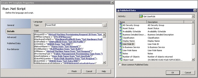
The screenshot in Figure 4-3 illustrates the power of the Orchestrator data bus. In this example the runbook contains a Windows PowerShell script. The Windows PowerShell script is able to utilize the data bus to populate the value of variables in the script. At runtime, the script used subscribes to the published data which is substituted in the script (represented by the blue hyperlinks below). The right side of the screenshot illustrates that any data published by previous steps in the runbook on the data bus is able to be selected.
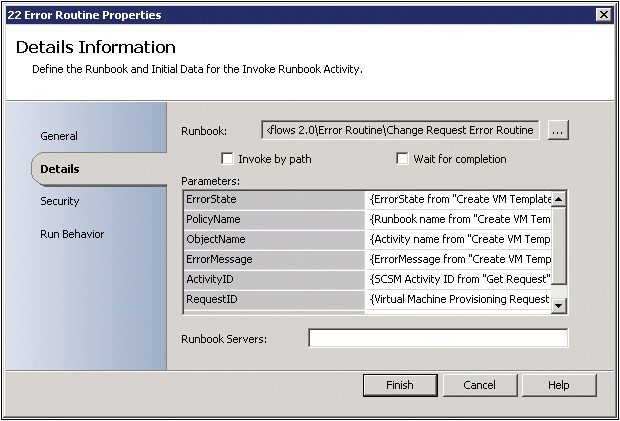
The Orchestrator data bus is an extremely powerful feature. While typically the data bus is used within a single runbook, there is also the ability to return data from one runbook to another. The Return Data activity allows you to return data from the current runbook to a runbook that invoked the current runbook. You configure the runbook data by configuring the data parameters in the Runbook Properties dialog box. This is a powerful concept and key enabler of modular runbook design and the framework that is described in subsequent chapters. The implications of this capability are that processes can be broken into small modular tasks (runbooks) and that each individual task or runbook can return status and data to a higher level runbook. This is logically equivalent to a function in code which can be called and which can return data. The screenshot in Figure 4-4 illustrates the configuration of a return data activity. These activities are typically the last step in each of the paths in a runbook. In this example, this is the Return Data activity for the error path of a particular runbook. What it shows is that the runbook is going to return six parameters and all but one are configured with data. The three parameters with data in brackets are examples of subscribing to data from the Orchestrator data bus. What that means is the value of those three parameters on the data bus at the time the Return Data activity is executed will be returned.
All of the Orchestrator activities described so far are included in a default Orchestrator installation. Similar to System Center 2012 Operations Manager with management packs, Orchestrator can be extended by integration packs, which are groups of new runbook activities specific to a particular purpose or management system. For example, Microsoft provides integration packs for the various System Center components such as the VMM integration pack. Orchestrator also has a large third-party ecosystem of integration packs created by Microsoft partners.
Microsoft provides integration packs for all of the System Center products, as well as other Microsoft and third-party products and technologies.
The following integration packs are currently available:
Active Directory Integration Pack for System Center 2012 - Orchestrator
Exchange Admin Integration Pack for Orchestrator in System Center 2012 SP1
Exchange Users Integration Pack for Orchestrator in System Center 2012 SP1
FTP Integration Pack for Orchestrator in System Center 2012 SP1
HP iLO and OA Integration Pack for System Center 2012 - Orchestrator
HP Operations Manager Integration Pack for System Center 2012 - Orchestrator
HP Service Manager Integration Pack for System Center 2012 - Orchestrator
IBM Tivoli Netcool/OMNIbus Integration Pack for System Center 2012 - Orchestrator
Representational State Transfer (REST) Integration Pack Guide for Orchestrator in System Center 2012 SP1
System Center Integration Pack for Microsoft SharePoint
Windows Azure Integration Pack for Orchestrator in System Center 2012 SP1
VMware vSphere Integration Pack for System Center 2012 - Orchestrator
Integration Packs for System Center:
Virtual Machine Manager
Operations Manager
Service Manager
Configuration Manager
Data Protection Manager
A wide range of integration packs are available through Microsoft partners. In some cases, vendors of management systems and hardware create integration packs for their Orchestrator to integrate with their solutions and in other cases, Microsoft partners, such as Kelverion, develop commercial integration packs for a number of third-party management systems (http://www.kelverion.com/products/).
Another source for Orchestrator integration packs and other utilities is the CodePlex site. CodePlex is Microsoft’s free open source project hosting site. The Orchestrator team maintains a list of CodePlex projects and resources at http://orchestrator.codeplex.com/.
Modular runbook design is a key objective which results in the maximum benefit from implementing System Center Orchestrator. The concept is very similar to object-oriented or service-oriented software design which emphasizes code libraries and code reuse. Our approach to systematic runbook design utilizes a modular approach to enable as high a return on investment of runbook development efforts as possible.
Before describing our modular runbook framework in detail, we must first reiterate that System Center Orchestrator operates through other management systems which must be in place in order for Orchestrator to be utilized. While basic runbooks can be created and executed using the built-in foundation objects regardless of whether other management systems are in place, typically for real-world scenarios Orchestrator will integrate with and act through other management systems such as the other System Center components or third-party management systems.
Generally, a mature management infrastructure provides several different layers of functionality such as those outlined in Figure 4-5.
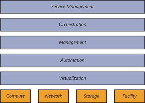
A rich automation layer is required. The automation layer must be enabled across all hardware components—including server, storage, and networking devices—as well as all software layers, such as operating systems, services, and applications. The Windows Management Framework—which comprises Windows Management Instrumentation (WMI), Web Services-Management (WS-Management), and Windows PowerShell—is an example of a rich automation layer that was initially scoped to Microsoft products, but that is now leveraged by a wide variety of hardware and software partners.
A management layer that leverages the automation layer and functions across physical, virtual, and application resources is another required layer for higher IT maturity. The management system must be able to deploy capacity, monitor health state, and automatically respond to issues or faults at any layer of the architecture.
Finally, an orchestration layer that manages all of the automation and management components must be implemented as the interface between the IT organization and the infrastructure. The orchestration layer provides the bridge between IT business logic, such as “deploy a new web-server VM when capacity reaches 85 percent,” and the dozens of steps in an automated workflow that are required to actually implement such a change.
The integration of virtualization, automation, management, and orchestration layers provides the foundation for achieving the highest levels of IT maturity.
The ability to automate all expected operations over the lifetime of a hardware or software component is critical. Without this capability being embedded in a deep way across all layers of the infrastructure, dynamic processes will grind to a halt as soon as user intervention or other manual processing is required.
Windows PowerShell and several other foundational technologies, including WMI and WS-Management, provide a robust automation layer across nearly all of Microsoft’s products, as well as a variety of non-Microsoft hardware and software. This evolution provides a single automation framework and scripting language to be used across the entire infrastructure.
The automation layer is made up of the foundational automation technology plus a series of single-purpose commands and scripts that perform operations such as starting or stopping a virtual machine, rebooting a server, or applying a software update. These atomic units of automation are combined and executed by higher-level management systems. The modularity of this layered approach dramatically simplifies development, debugging, and maintenance.
The management layer consists of the tools and systems that are utilized to deploy and operate the infrastructure. In most cases, this consists of a variety of different toolsets for managing hardware, software, and applications. Ideally, all components of the management system would leverage the automation layer and not introduce their own protocols, scripting languages, or other technologies (which would increase complexity and require additional staff expertise).
The management layer is utilized to perform activities such as provisioning the storage-area network (SAN), deploying an operating system, or monitoring an application. A key attribute is its abilities to manage and monitor every single component of the infrastructure remotely and to capture the dependencies among all of the infrastructure components. System Center 2012 has evolved to meet the requirements of managing a heterogeneous datacenter infrastructure.
The orchestration layer leverages the management and automation layers. In much the same way that an enterprise resource planning (ERP) system manages a business process, such as order fulfillment, and handles exceptions, such as inventory shortages, the orchestration layer provides an engine for IT-process automation and workflow. The orchestration layer is the critical interface between the IT organization and its infrastructure. It is the layer at which intent is transformed into workflow and automation.
Ideally, the orchestration layer provides a graphical interface in which complex workflows that consist of events and activities across multiple management-system components can be combined, so as to form an end-to-end IT business process such as automated patch management or automatic power management. The orchestration layer must provide the ability to design, test, implement, and monitor these IT workflows. System Center Orchestrator provides the foundation for such an orchestration layer, however, a structured and modular approach to its utilization is also required.
The Orchestrator designer does not enforce any standards or patterns for runbook design and is effectively an infinite canvas. While there are no strict limitations, there are several best practices for runbook design.
Each activity in Orchestrator (other than starting point activities) has both an input side and an output side, as well as a set of properties. Activities can have multiple inputs and outputs. Using just these constructs as well as the general left to right execution flow they encourage, we recommend using a “three rail” design. A “three rail” design is where the center rail performs the main action, audit or notification functions are at the top, and error handling is below. Figure 4-6 illustrates a small runbook utilizing this design layout.
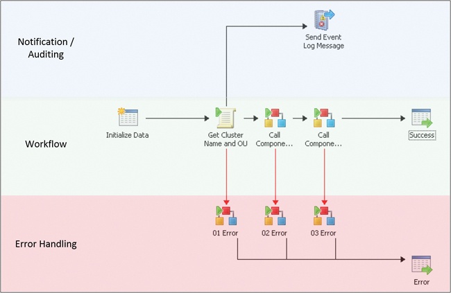
The primary functionality of the runbook is contained in the middle rail, proceeding from left to right. Each left to right link contains conditional logic capturing the success conditions required to proceed. All failure conditions, as well as “catch all” conditions for unexpected scenarios, should be captured in links down to the lower, error handling rail.
The use of link colors, labels, and line thickness can also visually enhance the runbook properties. We use default black links for success conditions and red links for error conditions. In cases where a subsequent step is executed multiple times in parallel, we use a different color and a label to indicate the previous step is returning multiple results which will each execute the subsequent steps in parallel. Figure 4-7 illustrates this approach.

The visual encoding of process logic in runbooks is a key differentiator between runbooks and large Windows PowerShell or other scripts. The visual nature of runbooks assists in understanding the functionality of the runbook particularly in cases where the original author has changed roles or someone new is now responsible for the runbook. The more standard and descriptive the naming (described in later chapters) and the more consistent the usage of the three-rail design, labels, and colors, the easier it will be to maintain a large library of runbooks.
The second rail of the three-rail design pattern for runbooks is error handling. A key mentality of enterprise runbook design is similar to software development where for each step you need to consider expected success states, expected error states, and unexpected states. That is the case both for each activity in the runbook and the runbook itself. In our framework, nearly every single activity in every runbook has an error path on the output side of the activity. The error path is enabled by configuring a link from the given activity to an Invoke Runbook activity which calls a common error handling routine (described shortly). The error path link must be configured with conditions such that it will only execute in error or unexpected conditions. The screenshot in Figure 4-8 illustrates an example of this.
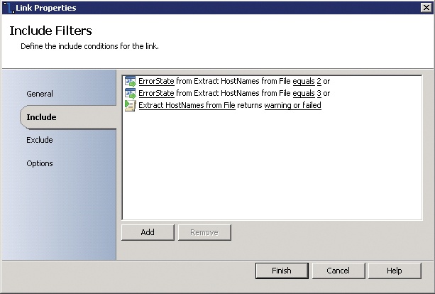
There are three cases where this error path will be taken in the runbook. The activity this link is attached to is a Run .Net Script activity which is executing a small Windows PowerShell script. The Windows PowerShell script will return a variable called ErrorState which contains the execution status of the Windows PowerShell script (values of 0 and 1 are successful while values of 2 or 3 indicate errors). So this error path in the runbook will execute if the value of ErrorState is 2 or 3. That covers cases of logical or expected errors in the script, meaning these will be errors that are handled in the script code. For unexpected errors where there is either a terminating or syntax error in the Windows PowerShell code or there is an internal failure in Orchestrator, the last condition in the screenshot should catch it. That condition contains the status of the activity itself (in this example, the Run .Net Script activity was named “Extract HostNames from File”). So the three conditions in this link should capture both expected and unexpected errors. We believe it is critical to configure every runbook step with such error handling.
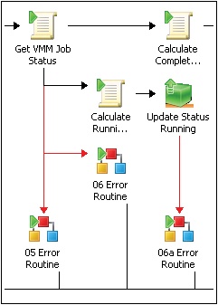
The second aspect of our error handling methodology is also critical to runbook portability and reuse and that is that the error path of each runbook activity links to an Invoke Runbook activity which calls a single error handling runbook. The screenshot in Figure 4-9 illustrates this visually.
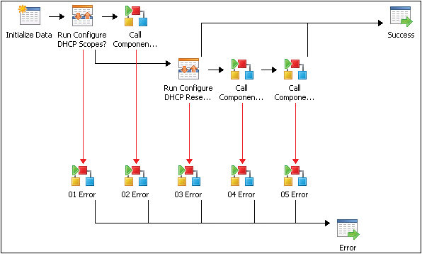
Each of the XX Error invoke runbook activities links to a single error handling runbook. The reason each activity links to an individual invoke command as opposed to just one invoke for all of them is that we want to be able to call the error handling runbook and pass data from the activity with the error condition. Examples include the name of the activity that failed as well as tracing data from that activity and so on. This is only possible with an invoke runbook attached to each activity.
While each activity has an associated invoke, all of the invokes call the same error handling runbook. The reason for this is to enable a single location (runbook) where error handling and logging is configured. An example of what the error handling runbook might do is create an Operations Manager alert or create an incident in Service Manager. Alternatively, if a non-Microsoft system, such as Remedy, is used for trouble ticketing, the error handling runbook could be configured to open a ticket in Remedy. The key concept here is that the error handling runbook functionality is configured in one place only and called by all other runbooks when needed. This abstraction means that you can change your error handling runbook and functionality without having to change all of your runbooks. This enables runbook portability to other environments where different ticketing or alerting systems are used while requiring only a change to the single error handling runbook to accommodate the new systems.
Finally, once the error handling runbook has been invoked, the final step of the runbook is a Return Data activity which will return the overall status of the runbook (which in this case would be an error status since the error path was taken).
Logging in runbook design is also a key consideration. Particularly as you automate more complex processes, different steps may fail or systems may return errors. Troubleshooting large and complex runbooks or modular runbooks with many components is challenging without a robust approach to logging.
The diagram is from the perspective of the Create New VM activity in the middle of the diagram. Every activity in Orchestrator in general (other than starting point activities) typically begins with input from a previous step, in many cases including Orchestrator published data, then does some activity like run an activity or Windows PowerShell, and publish resulting data or status. The runbook must then determine if the step was successful, then determine whether to take the Success path or the Error path. The dialog boxes in Figure 4-10 show example inputs, published data, success, and error conditions for the highlighted activity.

This example follows the pattern used by every runbook step that executes a Windows PowerShell script using the design patterns in this book. All Windows PowerShell scripts must publish three pieces of data, the most important being the ErrorState variable. There are four acceptable values:
0 – Success
1 – Success with Info
2 – Error
3 – Fatal Error
The branching logic after each Windows PowerShell step is triggered based on either the ErrorState value, or the status of the Orchestrator activity itself. So to succeed on the Success path, the value of ErrorState must be 0 or 1. If the value of ErrorState is 2 or 3 or the Orchestrator activity itself threw a warning or error, the runbook will branch to the Error path.
The Error path in all runbooks using this framework is an Invoke Runbook activity that calls a separate Error Routine control runbook which contains the desired error logging functionality (such as generate an event log message, create an Operations Manager alert, or create a Service Manager incident).
Each runbook must also publish a final status (represented by the Success and Error publish policy data objects). This status can be used by a parent control or initiation runbook calling the component runbook to determine what to do next based on the outcome of the runbook called.
Our modular approach to runbook design utilizes the tiers of runbooks: Component, Control, and Initiation runbooks. Component runbooks are the lowest level and most granular, aligned to the automation layer of management architecture described previously. Control runbooks are the intermediate tier aligning with the management layer of the architecture. Finally, Initiation runbooks are the top tier of the structure and align to the orchestration and service management tiers of the management architecture. Figure 4-11 illustrates these relationships.

The purpose of this structure is to deliver maximum reuse of runbook development efforts. Component runbooks are combined by a control runbook to achieve a particular purpose. The control runbook is called by an initiation runbook to begin the process automation. This structure enables a large library of component runbooks to be created over time and utilized by a wide range of control runbooks to automate various processes. The control runbooks can be called by different initiation runbooks so that process automation can be called from different sources such as service management systems, self-service portals, and so on.
Component runbooks in our framework are low level, typically single purpose runbooks with no external dependencies. Component runbooks are analogous to Windows PowerShell cmdlets or functions in scripting. They take a set of input parameters, perform an action, then exit with success or failure. The difference between a component runbook and an individual activity in Orchestrator is the addition of input parameters, error handling, and multiple output paths. In our framework, a component runbook typically consists of two or three Orchestrator activities. Some examples of component runbooks include: Install a Role or Feature in a Windows Machine or Reboot a Machine. Similar to Windows PowerShell cmdlets, the component runbooks use a verb/noun construct to indicate the action and target of the runbook.
As you can see from these examples, component runbooks are designed to be general purpose and usable by a wide range of higher level automation. Many different processes and higher level runbooks may need to install a role in Windows or reboot a given machine. Rather than rewrite this functionality in hundreds of different locations, our framework leverages the ability of one runbook in Orchestrator to call another runbook and evaluate the results to implement a modular structure.
Component runbooks, given their low level focus, typically do not include process logic. Including process logic at this level would limit the component runbook’s utility in multiple scenarios or other processes.
In our framework, we suggest categories of component runbooks dealing with similar functionality. For example, a category (and associated runbook folder) called Computer Management might contain component runbooks for starting, rebooting, or turning off a computer. Other runbooks such as pinging a computer could also be created.
Control runbooks are the next level up from component runbooks. The purpose of a control runbook is to encode process logic and call appropriate component runbooks to execute functionality. Control runbooks typically include process and branching logic such as “proceed to the next step only if the current step is successful or returns a particular value,” An example would be a runbook that first pings a computer to see if it is online, then attempts to check the server to see if a particular process is running on the server and if not, reboot the server. The three individual steps (ping, check for process, and reboot) would be defined as component runbooks. The control runbook would encode the process logic and order of execution of the component runbooks and have different execution paths for success, failure, and unexpected conditions.
In the example so far, a combination of three component runbooks and one control runbook has been described. While modular, so far this example could have been accomplished with one larger combined runbook. The power of the modular approach emerges when considering additional processes that might be automated. For example, a patching or updating process may need to reboot a given machine one or more times. Using the modular approach, a control runbook for the patching process could call the same server reboot component runbook as the previous example used. Two different control runbooks automating two distinct processes could use some of the same components, meeting the objectives of code reuse and maximum return on investment.
As modular as component and control runbooks are, one more tier is required in our framework. The highest level tier is called an initiation runbook. The purpose of an initiation runbook is to call one or more control runbooks which then call one or more component runbooks. The reason for this third tier is that there are a variety of ways in which a process may be initiated. A management system such as Operations Manager or Service Manager may need to trigger an automated process. A self-service portal or service catalog may be a location where automated processes are listed and made available for execution.
Separating the method for initiating automation from the automation itself is key to a modular design. This improves modularity and reuse of investments in component and control runbooks. The modularity described so far enables the different tiers of runbooks to be updated and maintained independently, provided they maintain the expected input and output results, each tier or runbook can be updated without affecting the other tiers or runbooks. This enables the creation of a growing library of component runbooks as well as a library of fully automated processes using control runbooks, and finally a variety of initiation runbooks linking external triggering systems to the automation library.
Many IT organizations have identified a need to streamline IT operations and processes, reduce the burden on IT resources, and improve their ability to meet the complex needs of the businesses that they support. This can often be accomplished by automating time-consuming and repetitive manual processes, a method used to keep the world’s largest and most efficient datacenter facilities operating with minimal manual oversight. Armed with a basic understanding of System Center Orchestrator, a wide range of possibilities for automation typically emerges. The key to getting the most out of Orchestrator is a structured approach to deciding what processes to automate founded on a return on investment (ROI) methodology.
The greatest ROI for IT process automation is typically found in areas with high repetition or high complexity requiring a large amount of involvement by IT staff. An analysis of help desk calls and activities over an annual basis is an excellent place to start. Often a large percentage of calls are the result of a small number of root issues which are prime candidates for automation. Analysis of deployment activities (such as desktops, servers, applications) are also prime candidates for process automation. Finally, surveys of IT staff can also identify areas of inefficiency that are candidates for automation. The initial goal is to generate a large list of potential automation targets. The next step is to apply cost information to each of the existing processes to determine how much one instance of the process costs to perform today using existing systems or manual effort. Next, attempt to determine the number of times this process is required in a year. This leads to a current total annual cost of executing the process. With this calculated for all of the identified processes, they can be stack ranked from most to least expensive. As processes are automated, the library of component, control, and initiation runbooks will begin to grow. Over time the results in the ROI analysis for new runbooks becomes more attractive as well as many of the steps for new processes will already exist in the component runbook library from prior efforts.
With the highest ROI candidates identified, detailed requirements gathering for each high ROI process is the next step.
The requirements gathering process for automation using Orchestrator runbooks is the first step in a process of breaking down a high level objective such as “automate scale-out of a web farm based on performance monitoring” in progressively more detailed levels. In the requirements gathering phase, the following items should be identified and documented:
The process to be automated (for example, . scale-out a web farm)
The conditions that trigger when the automation should be performed (for example, when transactions per node exceed 1000 transactions/sec)
The definition of scale out for this process (add another web server virtual machine, deploy the web application, add to load balancer)
Success validation criteria (for example, requests per node drop to under 1000 transactions/sec)
Expected failure conditions (for example, web virtual machine fails to deploy, load balancer fails to distribute load)
How to capture unexpected failure conditions (for example, requests per node fails to drop under 1000 transactions/sec or any individual step in the automation fails)
Does the process require any human approvals or can it be automated end to end
What data needs to be logged or traced through the execution of the process
The items in the requirements list define the process and surrounding conditions. The requirements list does not include detailed information about the process itself or how it will be automated, which is the next step in the development process.
It is important to optimize processes before automating them. The existing process may not be as efficient as it could be, and automating an inefficient process will never be as effective as automating an efficient process. In this next step of process automation and runbook development, the existing process should be fully mapped and documented. In many cases the existing process may be manual, may span organizational units, and have any number of different activities and challenges. Full understanding and documentation of the current process is critical in both understanding what must be performed as well as identifying areas that can be eliminated or streamlined.
One method for breaking down an existing process or system is capturing this data in a service map that contains all of the components that define a service such as the three-tier application or web farm used as an example previously. The Microsoft Operations Framework (MOF) defines a simple but powerful structure for service mapping that focuses on the software, hardware, dependent services, customers, and settings that define an IT service and the various teams that are responsible for each component. In this case, the application consists of the database, application, web farm virtual machines, the physical servers on which they run, dependent services such as Active Directory and DNS, the network devices that connect the servers, the LAN and WAN connections, and more. Failure of any of these components causes a service interruption. You can find a sample service map diagram at http://aka.ms/SCrunbook/files.
The service mapping exercise helps to fully define the full set of hardware, software, services, and settings that might be impacted by the particular process being automated.
The next step is to take the desired process (for example, scale out a web farm based on performance monitoring) and list all of the steps in the current process. A relatively poor manual process might look like this:
Customers call the help desk complaining of slow website performance
The help desks waits until multiple tickets over several days all complain about performance
The ticket is escalated to tier two which looks at monitoring data and sees that the website is available and not currently showing performance issues
More tickets come in complaining of performance issues so the tickets are escalated to tier three
Tier three support identifies that for several peak periods every day, website performance is poor due to load on the web farm
Tier three transfers the ticket to engineering which then decides to add a new virtual machine to the web farm
An engineer then manually deploys and configures a new virtual machine into the web farm
The engineer does not confirm that the new VM reduced the load on the farm but closes the ticket anyway
The next day more tickets come in about slow performance
The help desk knows that a new server was added to the farm so they assume that’s not the issue and begins analyzing the application and database tiers as well as storage
Eventually, a tier three help desk resource identifies that the newly added web server virtual machine was not properly added to the load balancer so is not servicing any requests
Finally, once the new web server is added to the load balancer, the root issue is resolved and performance is within the expected parameters
Clearly the above process is slow and inefficient. Despite that, many of the steps performed are hard requirements and must be captured. Also, it is important that several different parts of the IT organization shared responsibility throughout the process. It is critical to identify all of those groups and steps so that the process can be streamlined as much as possible to the point that the remainder is the minimum number of steps required to meet the capture requirements.
The new runbook design should contain information about the target functionality, an outline of all the steps included in the runbook, and the layers or products in the infrastructure where those steps must be performed.
Another process commonly targeted for automation is the update or patch management process for servers. The following diagram illustrates how to break down a process and map each of its steps against the management architecture layers discussed previously. This process shows a combination of automated steps as well as several points of human interaction and approvals at the service management layer. The final, streamlined process should be captured in a process map similar to Figure 4-12.
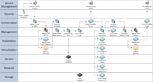
Once the streamlined process has been mapped, the next phase of runbook development can begin which is the documentation of functional specifications for each of the steps in the process (components), the overall process itself (control), and the conditions or triggers for the process (initiation).
The first step in documenting functional specifications is to take the target process and its process map and break it into the three types of runbooks we defined in previous sections. Each low level step of an individual task in the process should be defined as component runbooks. Using the scaling out of a web farm example, the following component runbooks would be required:
Create New Virtual Machine
Deploy Web Application to Virtual Machine
Add Virtual Machine to Load Balancer
Monitor Web Farm Performance
With those components outlined, the overall workflow or structure of the process should be captured using a control runbook. The control runbook would execute whenever the web farm needs to be scaled out and would first create a new virtual machine, deploy the web application, add it to the load balancer, then validate improved performance. The control runbook would call each component runbook in order and determine whether each was successful or failed and determine the final status of the process. Finally, with the component and control runbooks outlined, one or more initiation runbooks would be defined. In this case, two would be relevant. The first would be an initiation runbook which would be synchronized with System Center Service Manager such that the Service Manager service catalog would have a service request called “Scale Out Web Farm” allowing the operator to manually trigger the execution of the initiation runbook, which would then call the control runbook which would subsequently call all the component runbooks. The second initiation runbook would be a monitor runbook which would monitor web farm performance metrics in Operations Manager and when thresholds are exceeded, it would call the control runbook to scale out the web farm.
In the previous example we have defined a relatively small set of runbooks to automate a relatively complex process. We defined it in a way that allows two methods for the process to be triggered (manually or automatically) and by using the modular structure, much of the work (that is, all the component runbooks) are usable across a wide range of processes.
With this logical outline in place, each of the runbooks defined must have a set of functional specifications created so the runbook authors can create it in Orchestrator. The functional specifications for runbooks should contain the following elements:
Name
Description
Use cases
Inputs
Runbooks utilized (if this is a component runbook this would be blank, for control or initiation runbooks this should list the other runbooks it calls)
Scripts or code requirements
Integration packs required
Variables required or utilized
Connections to other systems
Other dependencies
While this may seem like a significant amount of documentation for what might be a relatively simple process, it is critical to realize that with the modular framework outlined in this book, most runbook work and documentation will be utilized many times over and likely improved over time through new versions of the runbooks. A solid foundation of documentation is important for long term optimization. In subsequent sections we outline standards and patterns for runbook documentation and versioning.
With the initial functional specifications drafted, runbook authoring and development can begin. Typically, runbook development will begin by creating and testing all of the required component runbooks. Since component runbooks represent the bulk of the functionality utilized, they must be created and tested first. Once each component runbook is completed and tested (analogous to unit testing in code development), then work on the control runbook can begin. The control runbook will call each component runbook and control the flow of execution such as any sequential or parallel steps. The control runbook will proceed or branch depending on the results. The control runbook and overall flow should be tested under many different conditions and scenarios (analogous to integration testing in code development). Finally, the initiation runbooks can be created and tested.
Since the investment was made to document functional specifications at each level, multiple runbook authors can work at the same time with the team’s efforts culminating in the control and initiation runbook testing. In subsequent sections we describe runbook naming, versioning, and collaborative development. During the process of development, the runbook functional specifications should be updated with as-built design documentation, diagrams of the runbooks and process flow, and so on. At the end of the development process the functional specification should represent all of the runbooks requirements and design.
The Orchestrator Runbook Tester is a key feature that assists in the runbook design process by providing the ability to test runbook functionality prior to implementation of your runbooks in a production environment. The Runbook Tester provides capabilities similar to a code or script debugger in that it allows you to set breakpoints in your runbook, step through your runbook activities one at a time, and view the status of all variables and value on the runbook’s data bus. The Runbook Tester is critical to the development of component run books (since the Runbook Tester can only test one run book at a time and not follow invokes to other run books). The Runbook Tester enables unit testing the component runbooks.
For testing control and initiation runbooks, a lab environment with all the systems required for the given process must be in place. It is critical to test many different scenarios and permutations to validate the enterprise readiness of the process being automated. At a minimum, the full process should be tested end to end and results validated. Additionally, many other scenarios should be tested such as multiple simultaneous executions of the process, injection of failure conditions or losses of connectivity, execution of the runbooks while other processes and runbooks are running, and so on. The goal is to test as many production conditions as possible and to verify not only the success paths through the runbooks but also the failure paths, different triggering conditions, error handling, and logging.
This section discusses the naming, folder structure, and versioning of runbooks.
A carefully specified naming convention will help runbook authors understand how runbooks relate to one another as they flow within the folder structure in which they are organized, and will better facilitate on-going agile release cycles that may involve the addition of new runbooks.
The recommended folder structure for a runbook library specifies a single root folder containing three additional folders named Component Runbooks, Control Runbooks, and Initiation Runbooks. This structure better enables versioning, and allows for the future addition of new runbook types.
Because component runbooks are not bound to any specific scenario, but instead are leveraged by multiple scenarios, it is most effective to organize them into feature-specific runbook collections. For instance, a folder named Firewall should contain all runbooks related to firewall configurations. This approach enables those feature-specific runbooks to be centrally maintained while providing functionality that can be accessed by multiple control runbooks; each expressing a different scenario. For example, a control runbook used for Hyper-V Replica and a control runbook for VDI deployment can both leverage one instance of a runbook dedicated to firewall configuration.
Next, folders should be created within each feature-specific component runbook folder to accommodate each version. Those folders should be named using a major version number that corresponds to the supported platform, and a minor version number that expresses each change made within that platform. For example, the feature-specific Firewall folder should contain a folder named 1.0 to support Windows Server 2008 R2, and a folder named 2.0 for Windows Server 2012. Those folders should then contain all the component runbooks related to the appropriate platform; for example, Windows Server 2008 R2 Firewall configurations, or Windows Server 2012 Firewall configurations. Additional folders should then be created within each platform-specific folder to accommodate each new version of those runbooks. For example, folders named 1.1, 1.2, and 1.3 should be created for versions of Windows Server 2008 R2 Firewall component runbooks, and folders named 2.1, 2.2, and 2.3 should be created for versions of Windows Server 2012 Firewall component runbooks.
It’s always a best practice to use the latest version of a platform-specific component runbook for each new deployment. To that end, if a new runbook version includes interface changes, either adding or removing input parameters, then the new runbook version will stay in the same folder. Its name will remain unchanged although its interface signature will change. Conversely, if a new runbook version does not include interface changes then the new version will be advanced to the next version’s folder; for example, moved from the 1.0 folder to the 1.1 folder.
To upgrade existing deployments it is possible to deploy the updated version side-by-side with the existing version. This way the option will exist to use the updated runbook version while having no impact on existing runbooks.
When a new feature is introduced along with a new platform, a new feature-specific folder should be created that contains only the platform-specific folder with which that feature was released. For instance, the data deduplication feature was released with Windows Server 2012; therefore, the feature-specific Data Deduplication folder should only contain a 2.0 folder, and not a 1.0 folder.
Because control runbooks are bound to a specific scenario, a new folder should be dedicated to each scenario being modeled. For instance, new folders should be created with names like Hyper-V Replica, and Azure VM Provisioning.
Next, folders corresponding to each version release should be created within each scenario-specific control runbook folder. Those folders should be named using a major version number that corresponds to the supported platform, and a minor version number that expresses each change made within that platform. For example, the scenario-specific Azure VM Provisioning folder should contain a folder named 1.0 to support Windows Server 2008 R2, and a folder named 2.0 for Windows Server 2012. Each version folder should contain all the control runbooks released along with that version. A new version folder should be created for each increment that includes new control runbooks that model new (additional) use-case scenarios.
To ensure versions can be installed side-by-side without breaking previous deployments, existing control runbooks that haven’t changed should roll forward from the previous release while only new and changed control runbooks should be included in a new version release.
Figure 4-13 outlines a sample Orchestrator runbook folder structure using the modular approach and version control guidance outlined in this section.
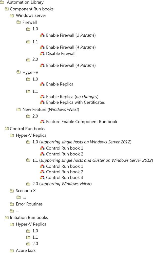
The primary goal of an automation library versioning system is to facilitate an ongoing, iterative development process where new control runbooks may be released, along with their supporting component runbooks, as their development and testing processes are completed. What’s more, the system should enable runbooks corresponding to separate use-case scenarios to be released independent of one another. The system should ultimately enable the automation library to grow organically over time. A stable release management process is required to avoid breaking existing code while deploying new runbooks.
To facilitate these goals the following schema will be used:
major.minor.revision.build
For component runbooks, the major, minor, revision, and build schema will use the following definitions.
major: An increment should be created to accommodate the addition of each new platform. For instance, 1.0 should be created for Windows Server 2008 R2, and 2.0 should be created for Windows Server 2012.
minor: An increment should be created each time a change is made either to a component runbook’s interface, or to its behavior. The addition of a new component runbook should also drive a corresponding increment. For instance, version 1.0 would contain the Enable Firewall runbook, but the addition of the Disable Firewall runbook would drive the creation of version 1.1.
revision: An increment should be created each time a control runbook is updated either to alter its implementation or to address bugs.
build: This value is set to the date of the build using the (YYYYMMDD) format each time the code is built. For instance, 1.2.2.20130119 represents the version 1.2.2 being built on January, 19th 2013.
For control runbooks, the major, minor, revision, and build schema will use the following definitions.
major: This will be incremented in case of a new platform (for example, 1.0 for Windows Server 2012, 2.0 for Windows 2012 R2).
minor: This will be incremented in case interfaces or behavior/code of control runbooks are changed (for example, same runbook but more/different parameters) or new control runbooks are being added to the solution (for example, 1.0 supports only single host Hyper-V replica, and 1.1 supports also clustered scenarios for Hyper-V Replica).
revision: This will be incremented in case control runbooks are updated (either implementation changes or bug fixes).
build: This will be used to set the value to the date of the build (YYYYMMDD). An example for that is 1.2.2.20130119 for January, 19th 2013.
Every release will include a change log that defines all changes to the last release and a defined new version number.
Orchestrator does not provide a good means of versioning runbooks. To get around this limitation, and the fact that we are not using Orchestrator variables, we will use files that will host the version number for each runbook. This makes it easier to get and update the version information while deploying a new release of runbooks.
There are multiple options to store version information. The following is a subset of possible ways to implement that:
Description field
Database table
Files on disk
Every solution has some pros and cons, but our strategy is using files as we are using them for variables and status-driven scenarios already.
For every runbook, version information will be stored in an xml formatted file, which will be stored in the file system.
<xml>
         <run bookName>Enable Hyper-V Replica</run bookName>
         <description>This run book is used to enable Hyper-V Replica on a single
host</description>
         <version>1.0.0</version>
</xml>
The location of the version information is located relative to the path of the Orchestrator structure. The root path for all files is stored in the Orchestrator global variable Runbook Root File Path. Details are described in the File-based runbook variables section of this document.
The name of the version information file is always be run bookVersion.xml
Team Foundation Server (TFS) enables collaborative software project development by offering features to facilitate team development; source code control, data collection, reporting, and project tracking.
Unfortunately, System Center Orchestrator doesn’t support a native TFS Integration out of the box. Therefore, if using TFS for multiple author runbook development or development teams, it is critical to define standards and practices for using TFS with runbook development. Orchestrator supports exporting and importing runbooks as xml-notated files which can be stored in TFS for source control. Runbooks can be exported individually, on a folder-level, or the entire folder structure. As this process is manual it can take a significant amount of time to export all runbooks individually.
To automate the export and TFS Check-In of runbooks, a proof of concept exists that is described at http://opalis.wordpress.com/2012/08/06/automating-the-export-and-tfs-check-in-of-workflows/.
In addition to importing and exporting runbooks, the source code for scripts in runbooks, such as Windows PowerShell, can be maintained as source code files as well.
Once all of the identified runbooks have been designed, authored, and tested they can then be deployed into the production environment. A key tenet of our modular runbook framework is that all runbooks built using the framework should be portable between different Orchestrator environments such as development and production. The final runbooks from the development environment can be exported and then imported into the production environment. Once the runbooks have been imported into the production environment, any initiation runbooks which utilize a monitor starting point activity should be manually started. The orchestration console can be used to monitor which runbooks are running and to validate that all monitor runbooks are running.