CHAPTER 6
Operating system deployment tips
Microsoft System Center 2012 Configuration Manager provides a highly flexible, automated solution to fully deploy and configure servers and desktops from any initial state, including bare-metal deployments. This enables IT administrators to provide an end-to-end solution for the installation and configuration of Windows, by delivering applications, updates, patches, and security fixes in a single distribution. This chapter covers some tips and tricks to operating system deployment.
Boot images
The Windows ADK is used to create Windows PE boot images that are used in Configuration Manager to deploy operating systems via PXE, CD-ROM, USB, or hard disk. Windows PE boot images are available in four current versions: 3.0, 3.1, 4.0, and 5.0. Windows PE 4.0 boot images do not work on some older hardware or versions of ESX or VMware Workstation that either do not support Windows 8 or do not have support for NX, PAE, and SSE2. As of Configuration Manager 2012 SP1 CU2, the ability to add Windows PE 3.1 boot images is now available to support these limitations.
Enabling F8 command prompt support
F8 command prompt support is an essential testing and troubleshooting tool that should be added to all of your boot images. Without it you will not be able to validate IP settings, disk configurations, drivers, or log files to assist in troubleshooting. Below are the steps required to configure F8 command prompt support in your boot images.
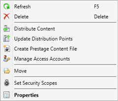
1. Open the Configuration Manager console and expand Software Library, Operating Systems, Boot Images, right-click your boot image, and then select Properties.
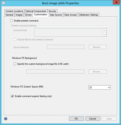
2. Click the Customization tab, select the Enable Command Support (Testing Only) check box, and then click OK to save and Yes on the next dialog to distribute to the distribution points.
Boot image driver management
Just like operating system images, boot images require drivers for various components such as network, disk, USB 3.0, video, and so on. Most drivers are included in box depending on the Windows PE and operating system versions being used, but in some cases you will need to add additional drivers. This can be a challenging step, and less is more when it comes to boot image drivers. You can easily end up with a non-functional boot image if you add incompatible drivers.
Various OEM’s offer driver packs with a subset of drivers that you might need for your boot image. It is recommended that you identify your requirements and include only the drivers you need. For example, you might not need RAID controller drivers depending on what you plan to deploy, so including them unnecessarily adds extra storage and administrative overhead for testing. It is also best to test against a lab server or non-production boot image before updating drivers to avoid extensive downtime while in production deployments.
Verifying missing drivers in your boot images can sometimes be challenging. One way to make this process easier is to use F8 command line support. Once you have a command prompt you can take advantage of useful functions like diskpart to validate that your Mass Storage Controller is working properly, you can use ipconfig to verify that your network stack is functioning, and you can test missing drivers with drvload to see if you have the correct driver to add to your boot image. Below is a quick step-by-step procedure for using drvload to verify that you have the proper driver.
1. Determine the driver that is missing and download it to media.
2. Insert media and change directory to the folder holding your INF files.
3. Run drvload.exe NameOfYour.inf.
4. Validate that you can access the disk or obtain an IP address
5. Add to a boot image in Configuration Manager.
Optional components
Windows PE Optional Components or Feature Packages allow you to extend Windows PE with additional languages and functionality. By keeping the feature packages external, the footprint remains small and you can tailor each boot image to your own organizational needs. For a complete list of optional components, see the following article: http://technet.microsoft.com/en-us/library/hh824926.aspx.
The following optional components might be included by default, but this will vary depending on your needs:
![]() Windows PowerShell (WinPE-DismCmdlets)
Windows PowerShell (WinPE-DismCmdlets)
![]() Storage (WinPE-EnhancedStorage)
Storage (WinPE-EnhancedStorage)
![]() HTML (WinPE-HTA)
HTML (WinPE-HTA)
![]() Windows PowerShell (WinPE-StorageWMI)
Windows PowerShell (WinPE-StorageWMI)
![]() Microsoft .NET (WinPE-NetFx4)
Microsoft .NET (WinPE-NetFx4)
![]() Windows PowerShell (WinPE-PowerShell3)
Windows PowerShell (WinPE-PowerShell3)
![]() Recovery (WinPE-WinReCfg)
Recovery (WinPE-WinReCfg)
Keep in mind that the smaller the footprint of your boot images the faster they will load and the less memory will be required to cache the contents, so don’t add everything just in case you might use it down the road.
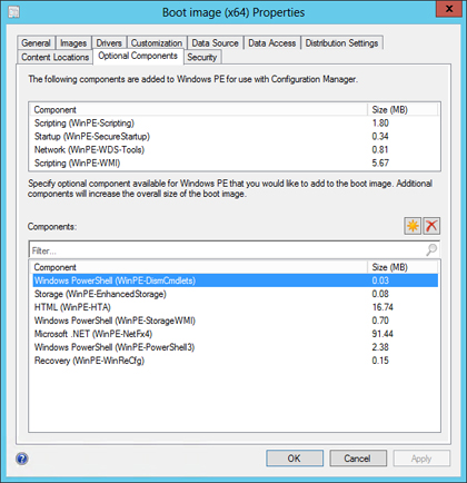
FIGURE 6-1 Windows PE Optional Components.
Adding Windows PE 3.1 to Configuration Manager 2012 SP1 CU2
The following procedure shows how to add Windows PE 3.1 to Configuration Manager 2012 SP1 CU2.
1. Install the WAIK 3.0 package on a remote system.
NOTE It is not recommended to have the ADK and WAIK installed on the same system.
2. Install the WAIK 3.1 Supplement update package. To install the supplemental update, open a command prompt and type the following command:
E:>xcopy E: "c:Program FilesWindows AIKToolsPETools" /ERDY

NOTE A total of 1,131 files should be copied.
3. Open the Deployment Tools Command Prompt.
4. Follow the guide on how to create a custom boot image at: http://technet.microsoft.com/en-us/library/dd744533(WS.10).aspx
NOTE Be sure to add the following required components:
![]() WinPE-Scripting
WinPE-Scripting
![]() WinPE-WMI
WinPE-WMI
![]() WinPE-WDS-Tools
WinPE-WDS-Tools
![]() WinPE-WDS-Tools
WinPE-WDS-Tools
5. Optionally, add drivers to the WIM image before completing step 6.
MORE INFO For more information, see http://technet.microsoft.com/en-us/library/dd744355(v=WS.10).aspx#AddDriverDISM.
6. Copy the boot.wim file created in step 4 to your Configuration Manager server.
7. Name the boot image appropriately for good housekeeping, WinPE 3.1 Boot Image x86.
8. Open the Configuration Manager console and expand Software Library, Operating Systems, Boot Images.
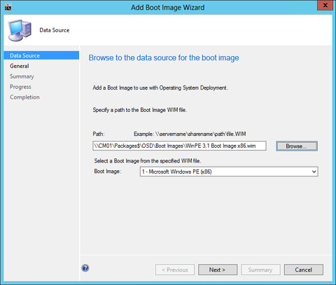
9. Select Add Boot Image.

10. Specify the UNC Path to your custom boot image and click Next.
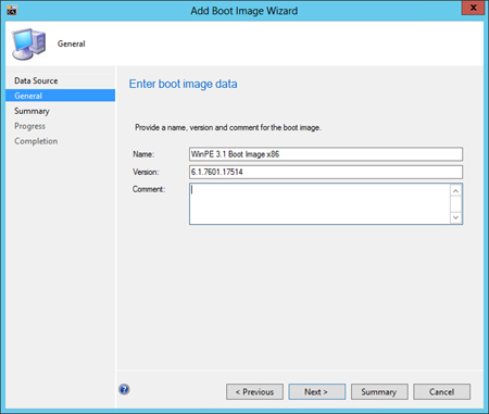
11. Type the Name and Version of your boot image and then click Next.
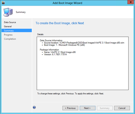
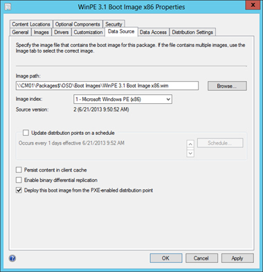
12. Click Next on the Summary page.
13. Next deploy the boot image to PXE-enabled distribution points by selecting the Deploy This Boot Image From The PXE-Enabled Distribution Point” checkbox in the boot image properties dialog box.
You should now have a functional Windows PE 3.1 boot image to use with your legacy systems.
NOTE Some tabs will be unavailable in the boot image properties dialog box; this is normal because the following options are not supported with Windows PE 3.1 boot images:
![]() Installing additional optional components through Configuration Manager
Installing additional optional components through Configuration Manager
![]() Adding drivers
Adding drivers
![]() Setting scratch space
Setting scratch space
![]() Configuring a prestart command
Configuring a prestart command
![]() Configuring a background image file
Configuring a background image file
![]() Enabling and disabling command prompt support (debug mode)
Enabling and disabling command prompt support (debug mode)
Drivers
Driver management in Configuration Manager is one of the most debated topics in operating system deployment and for good cause. It can easily become one of the biggest pain points you face. Best practice is to build a solid driver store that is easy for you to maintain and to know what you have in your environment. Michael Niehaus (http://blogs.technet.com/b/mniehaus/default.aspx?PageIndex=1) and Johan Arwidmark (http://deploymentresearch.com/Research.aspx) both have very detailed blog posts on the subject with examples of sound driver stores if you would like to find out more information.
Driver signing
For 64-bit versions of Windows Vista and later versions of Windows, driver code signing policy requires that all driver code have a digital signature. In addition, certain configurations of 32-bit versions of Windows Vista and later versions of Windows also require driver code to be digitally-signed in order to access next generation premium content that is controlled by the content protection policy.
You would think that all OEMs are signing their drivers, but sadly this is not the case. You might also encounter and issue with digital signatures when you alter the driver to adjust some of the settings enabled or disabled by default. By doing this you are essentially breaking the digital signature and the driver must be re-signed with a trusted certificate in your environment or by the vendor again. You can sign the drivers yourself, but it is not recommended to the average administrator. However, if you are interested in doing so, you can find great resources online with detailed instructions on the process.
Driver maintenance
Good housekeeping seems like a chore, but untangling a web of disorganization can certainly consume a lot more of your time. You could spend hours finding all of the right drivers for use in your organization. If you spend that much time gathering drivers, you should invest in a structure that is easy to manage and maintain so you can know at a glance what’s in your driver store and be able to add or remove models or drivers on a whim. Figure 6-2 shows a sample folder structure to get started with your driver store. The structure used here is:
Operating SystemOEMModelDevice Version

FIGURE 6-2 Sample folder structure for drivers.
It’s important to regularly check your OEM for updated drivers not only to improve device functionality but to also patch security vulnerabilities in the drivers.
UEFI
The Unified Extensible Firmware Interface (UEFI) is meant to replace the legacy BIOS interface of today. UEFI Spec 2.3.1 is the latest version available and is a requirement for Windows 8 certified machines. There are two classes of UEFI: class 2 devices, meaning they support the BIOS compatibility mode known as Compatibility Support Module (CSM), and class 3 devices, which are native UEFI systems only. The advantages of UEFI include:
![]() Full memory access (32-bit or 64-bit)
Full memory access (32-bit or 64-bit)
![]() CPU independence (enabling UEFI on x86, x64, ia64, and even ARM computers)
CPU independence (enabling UEFI on x86, x64, ia64, and even ARM computers)
![]() Faster initialization
Faster initialization
![]() Support for larger boot disks (larger than 2.2 terabytes)
Support for larger boot disks (larger than 2.2 terabytes)
The following are a few tips concerning UEFI support in Windows:
![]() Native class 3 UEFI devices support only Windows 8 and newer.
Native class 3 UEFI devices support only Windows 8 and newer.
![]() Boot images must be the same architecture as the operating system being deployed.
Boot images must be the same architecture as the operating system being deployed.
![]() Use the _SMSTSBootUEFI task sequence variable to determine if a machine is in UEFI mode.
Use the _SMSTSBootUEFI task sequence variable to determine if a machine is in UEFI mode.
![]() Always build your reference image on a virtual machine in BIOS compatibility mode.
Always build your reference image on a virtual machine in BIOS compatibility mode.
![]() Server 2012 or higher is required for UEFI x86.
Server 2012 or higher is required for UEFI x86.
![]() Server 2008 R2 or higher is required for UEFI x64.
Server 2008 R2 or higher is required for UEFI x64.
![]() USB boot media must be formatted as FAT32.
USB boot media must be formatted as FAT32.
![]() FAT32 has a 4-GB file size limit.
FAT32 has a 4-GB file size limit.
The typical disk layout for UEFI deployments looks like this:
![]() Recovery (NTFS, 300 MB)
Recovery (NTFS, 300 MB)
![]() System (FAT32, active, 300 MB)
System (FAT32, active, 300 MB)
![]() Microsoft Reserved Partition (MSR, 128 MB)
Microsoft Reserved Partition (MSR, 128 MB)
![]() Operating System (NTFS, 100%)
Operating System (NTFS, 100%)
Operating System Images and Offline Servicing
Windows image files, or WIMs, can be imported into Configuration Manager as Operating System Images. This can be in the form of the original install.wim from the product source ISO or DVD, or it can be your own custom WIMfile. WIMs have a catalog file associated with them that shows the state of all settings and packages in the image file. Additionally, an unattended.xml file can be used to control the state of the components, packages, and settings.
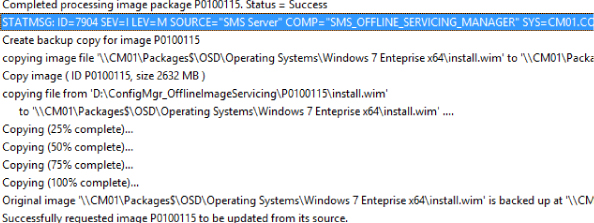
Configuration Manager 2012 includes a feature for applying updates to Operating System Images called Offline Servicing. This feature in the Operating System node under Software Library allows you to apply Component Based Servicing (CBS) updates to a WIM file offline. This allows for faster deployment times, reduced image recycle periods, and overall lower administrative effort to maintain Operating System Images. Following is an example of how to use this feature.
1. Open the Configuration Manager console and expand Software Library, Operating Systems, Operating System Images, and then select Schedule Updates from the ribbon.
2. Review the list of updates that meet the following criteria:
![]() They are CBS updates.
They are CBS updates.
![]() They have been deployed in your Configuration Manager environment. (This helps limit the selection of updates to those that have been deployed or tested in your enterprise.)
They have been deployed in your Configuration Manager environment. (This helps limit the selection of updates to those that have been deployed or tested in your enterprise.)
![]() They have not successfully been deployed to your image file through the Offline Servicing feature.
They have not successfully been deployed to your image file through the Offline Servicing feature.
3. The updates are filtered to match the architecture of your image file. Select your updates and then click Next.

4. Unless you want to schedule the updates for a later time, accept the defaults and click Next, click Next again, and then click Close.
5. You can validate the progress by watching OfflineServicingMgr.log on the site server.
6. To see all of the updates that have been added to your image, review the Installed Updates tab in the image file’s properties dialog box.

Task sequences
Task sequences provide the mechanism for performing multiple steps or tasks on a client computer at the command-line level without requiring user intervention. Task sequences do not represent a full scripting language but are highly customizable and include a large subset of built-in actions and pre-configured templates.
MDT integration
Microsoft Deployment Toolkit (MDT) is a Solution Accelerator for operating system and application deployment. MDT supports deployment of client and server operating systems. It can be used as a standalone or integrated into Configuration Manager. By integrating MDT into Configuration Manager, you gain the ability to use the additional templates, actions, and customized boot images and to call external scripts, databases, web services, and much more to enhance and streamline your operating system deployment needs.
To integrate MDT with Configuration Manager, install MDT on your Configuration Manager site server or on any computer with the console installed that you might use to edit a task sequence. After you install MDT, follow the simple Configure ConfigMgr Integration Wizard, shown in Figure 6-3.

FIGURE 6-3 Integrating MDT with Configuration Manager,
MDT integration is relatively simple, requiring a set of binary files and XML extensions to be copied and a Microsoft Operations Framework (MOF) file to be compiled, all of which are done via the wizard during integration. A handful of issues could prevent this from working smoothly, commonly permissions issues, antivirus blocking, or corrupt WMI. After integration, you can open an existing or create a new task sequence to see all of the new options under the MDT node in the task sequence.
Static IP address assignment
Occasionally, you might require the use of static IP addresses. You might simply want to assign static IP addresses to your server systems during deployment, or DHCP is unfortunately nowhere to be found and you must work with what you have to get the job done. Luckily, this requirement isn’t too difficult to achieve. You can assign IP addresses on a collection level or via a custom startup script to assign the proper variables. Figure 6-4 shows an example of setting collection variables for a static IP address.

FIGURE 6-4 Configuring collection variables for a static IP address.
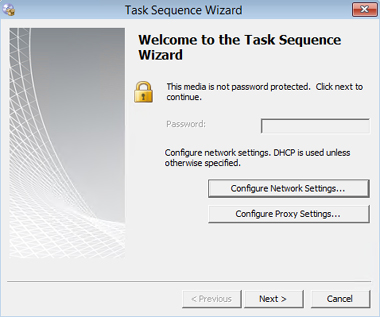
You can also create task sequence bootable media, which will generate a dialog box to enter the above information. Having bootable media is a requirement since it’s expected that if you can PXE boot, you already have an IP address and don’t need to statically assign an address in this manner.
1. Insert bootable media and click Configure Network Settings on the first page of the Task Sequence Wizard.
2. Supply your IP settings and click OK.
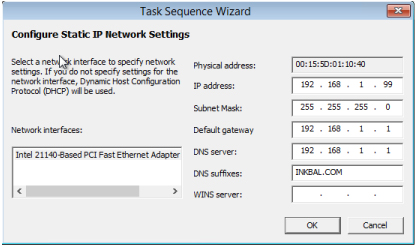
3. Verify that the IP address was assigned correctly by viewing the X:WindowsTemp SMSTSLogSMSTS.log file.
Enumerating available network adapters.
Reading adapter informaion for "Intel 21140-Based PCI Fast Ethernet Adapter (Emulated)"
Applying settings for Intel 21140-Based PCI Fast Ethernet Adapter (Emulated)
SetGateway("192.168.1.1")
EnableStatic("192.168.1.99","255.255.255.0")
SetDNSServerSearchOrder("192.168.1.10")
SetDNSSuffixSearchOrder("INKBAL.COM")
SetGateway("192.168.1.1")
Executing command line: X:windowssystem32cmd.exe/k
OSDPreserveDriveLetter
Configuration Manager 2012 SP1 includes a new variable to control the behavior of the drive letter assignment. This variable determines whether or not the task sequence uses the drive letter captured in the operating system image WIM file when applying that image to a destination computer.
Setting OSDPreserveDriveLetter=YES will deploy the operating system to the drive from which it was captured (see Figure 6-5). For instance, the install.wim is captured with the c: drive as the destination disk, so that would hold true with OSDPreserveDriveLetter set to true. In some cases, this setting does not produce the desired affect, but in most cases this will work fine.
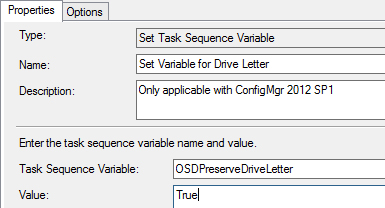
FIGURE 6-5 Setting the variable for the drive letter.
SMSTSPostAction
The SMSTSPostAction task sequence variable is a very handy addition and gives you the ability to specify a command to be run after the task sequence completes. For example, you can use this variable to specify a reboot action after the task sequence deploys an operating system to the device (see Figure 6-6).
Typically you would just add a simple restart computer step to a task sequence, but if you are trying to get Group Policy to process faster, this would not work since the task sequence disables Group Policy Object (GPO) processing during the task sequence. The SMSTSPostAction gets around this implication and offers many other possibilities as you can likely imagine. Additionally, it does not matter where you set this variable in the task sequence since it will be processed at the end regardless of location.

FIGURE 6-6 Configuring the task sequence to restart after it completes.
Extending task sequence logging
Logging in Configuration Manager can certainly be overwhelming at times. There are log files for just about everything, but the primary log file for operating system deployment is the SMSTS.log file, which will grow and grow and grow, depending on the size of your task sequence. One challenge is finding what you are looking for in the log, which can be complicated by the fact that once the log fills up, it rolls over and a new log file is created. By default only one rollover log is maintained and the rest of the log is purged.
When it comes to logging, sometimes more is better. Luckily, the Configuration Manager team has provided the ability to extend logging so you can have more to work with if you are troubleshooting something or simply want to verify what happened. CCMLOGLEVEL, CCMLOGMAXHISTORY, and CCMLOGMAXSIZE all are configurable in the installation properties of the ConfigMgr Client Installation step of the task sequence. By setting these variables, you will gain more robust logging (see Figure 6-7):
![]() CCMLOGLEVEL=0 Turns on verbose logging.
CCMLOGLEVEL=0 Turns on verbose logging.
![]() CCMLOGMAXHISTORY=6 Sets the number of log files to keep.
CCMLOGMAXHISTORY=6 Sets the number of log files to keep.
![]() CCMLOGMAXSIZE=2621440 Sets the log size to 2.5 MB.
CCMLOGMAXSIZE=2621440 Sets the log size to 2.5 MB.
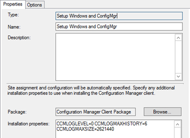
FIGURE 6-7 Configuring logging options.
Applications
Applications in Configuration Manager give you as the administrator flexibility in application delivery. An application can be targeted either at a user, at a device, or at the user’s device without having to know what the device name is before deployment. The application model has very granular control with requirements, dependencies, supersedence, revision control, and conditions.
Chassis type global conditions
Global conditions in Configuration Manager 2012 are rules that represent business or technical conditions that can be used to specify how an application is provided and deployed to client devices. Global conditions can be created from the Global Conditions node of the Configuration Manager console or from within the Create Deployment Type Wizard. Global conditions are accessed and used from the Requirements page of the Create Deployment Type Wizard. With the ability to target applications to laptops, desktops, or dervers, you can leverage the flexibility of Global Conditions within the new application model of System Center 2012 Configuration Manager.
When leveraging requirements within the application model, you can select a global condition for chassis type, which will then be evaluated before the content is downloaded from the server. This feature precludes the requirement for a collection evaluation or refresh unlike setting these types of criteria on collection queries. As a result, the process is more efficient then in prior versions of Configuration Manager.
MORE INFO For details about how to set up chassis-type global conditions, go to http://blogs.technet.com/b/brandonlinton/archive/2013/01/30/configmgr-2012-chassis-type-global-condition.aspx.
Installing applications that require interaction
Sometimes you run into a stubborn application that just won’t install during your task sequence. Perhaps you have gone down the road of initial troubleshooting by trying to install the application outside of the task sequence as a package or application and found that works fine. Perhaps you even tried manually running and the application works without a hitch. So why can’t you get this stubborn application to install during your task sequence?
In Windows Vista and above a security feature was implanted to isolate services in session 0 and make them non-interactive. Unfortunately, Configuration Manager task sequences run under the system context in session 0, so any application that requires interaction will fail or simply sit and time out. Luckily, the MDT Solution Accelerator team thought of this for User Defined Installations (UDI) and developed a handy executable that launches in a user session and makes the process interactive and visible to the technician and task sequence.
The following example shows how to launch an executable with ServiceUI.exe from the Microsoft Deployment Toolkit:
ServiceUI.exe -process:tsprogressui.exe YourApplication.exe
Application logging
One thing that is frequently overlooked is logging when packages and applications are created and put into Configuration Manager. Becausethis isn’t a requirement and because most of us are overworked, this step is easily forgotten event though it is essential to good package procedures and troubleshooting efforts.
Most common installers, such as InstallShield and Wise, offer logging capabilities in their applications, which can be used for advanced troubleshooting when things don’t go right. Here are a couple of quick examples:
Msiexec /I yourapplication.msi /qb! /l*v"%WINDIR%TempYourApplication.log"

Setup.exe /s /log "%WINDIR%TempYourApplication.log"
Troubleshooting
Operating system deployment troubleshooting is a “Where’s Waldo” of log files. With so many different logs and locations to look for things, it becomes a talent to master just the troubleshooting end of operating system deployment. Even after finding the logs and their locations, how do you decipher the detailed output in the logs? Luckily, an extensive list of online TechNet documents list all of the log files and what they are for. Now you just need to know how to use the best tools to read them, have a basic understanding of what to look for and where, and, during testing, set up central logging to make things easier on failed deployments.
CMTrace
The Configuration Manager Toolkit includes a utility called CMTrace.exe that is an advanced log file viewer that can open and read live log files and can also merge multiple log files into a single file with sorting options and error code lookups. Additionally, CMTrace will highlight certain parts of the log, such as errors, failures, warnings, and informational messages with the appropriate colors to make it easier to find information in the log file. Follow these steps to use CMTrace.
1. Open CMTrace.exe and find the error code that you want to research.
2. Select the Error Lookup option from the Tools menu or press CTRL+L.
3. Type the error and you should see a friendly, formatted message:

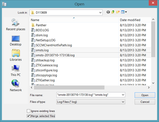
Merging log files can be incredibly beneficial when trying to trace the flow of an issue. Follow these steps to use CMTrace to merge log files.
1. Open CMTrace.exe and then press CTRL+O to access the Open dialog box.
2. Select the files you want to merge, select the Merge Selected Files check box, and click Open.
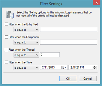
3. Now that you have a merged log file, you can also apply a filter to find just what you are looking for in the merged log files. Select Tools, Filter to access the filter settings (shown in the following screenshot).
Log locations
Configuration Manager log files are stored in a variety of locations, depending on the process that creates the log file. Table 6-1 lists some typical log locations where you might find log files depending on what point the system is at in the deployment process.
TABLE 6-1 Typical log file locations

Centralized logging
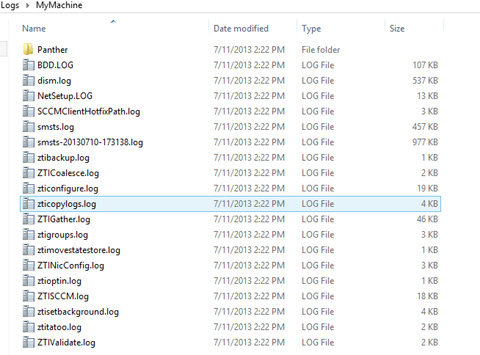
As mentioned earlier, MDT Integration gives you a lot of flexibility and control during operating system deployment. When it comes to troubleshooting log files you can see that there are a number of logs and a number of locations to find these logs, which can be daunting when under pressure.
MDT has a variable called SLShare that you can use in MDT Integrated task sequences to find all of the common log files and copy them up to a file share when the task sequence is complete. This makes troubleshooting a breeze as you can simply open your file share and review the logs that have been copied and placed in a folder named for the machine that was deployed.
Setup is simple: just create a share on your site server or somewhere on your network and set the SLShare variable in your task sequence or customsettings.ini file. Once completed, folders will be created under the Logs directory for each machine, like the example shown in Figure 6-8, which uses the following share:
SLShare=\CM01Packages$OSDLogs