
Introduction
I.1 Electric Power System and the Need for Change
Electric power system (EPS) is the infrastructure to generate, transmit, and distribute electricity. The existing EPS is the largest and most complex man-made system. The bulk electricity is generated in large power plants in the form of alternating current (ac) using synchronous generators (or alternators). The ac voltage is then boosted using transformers and transmitted via long transmission lines. After transmission, the voltage levels are decreased and the electricity is used for various industrial, commercial, and residential applications. Electrification has been the greatest engineering achievement of the twentieth century [1].
I.1.1 Review of Operational Principles of EPS
The existing EPS has a hierarchical structure with central power plants generating the electricity and sending to users through the transmission system. The power flow is unidirectional from Generation to Distribution via Transmission.
- Generation
- A Power Plant is an industrial plant to generate bulk electric power.
- Dominant sources of bulk electric energy are fossil fuels (coal, natural gas, petroleum), nuclear reaction, and stored water. Corresponding turbine types are steam (for fossil fuels and nuclear) and hydro turbines.
- Popular generator is the three-phase synchronous generator (ac, 50 or 60 Hz).
- Unit Transformer steps up the voltage at the power plant.
- Transmission
- High-voltage overhead lines (ac voltage is boosted using transformers).
- Meshed network to increase reliability.
- Voltage is stepped down at transmission substations.
- Distribution
- Voltage is further lowered at distribution substations.
- Medium to low-voltage transmission lines; radial feeder topology; pole transformers (three-phase and single-phase low voltage end users).
- Industrial, commercial, and residential users.
- Residential applications: cooling; heating; lighting; refrigerating; washing; drying; entertainment; cooking; etc.
The EPS is highly interconnected: many generation and transmission systems are connected together to form a large pool of energy resulting in a highly reliable system. Maintenance of such a large interconnected ac system in terms of synchronized, stable operation, and protection of all components while preventing cascading failures is the everyday challenge of electric utility companies.
I.1.2 Problems with the Existing EPS
According to US Energy Information Administration (EIA) [2], about ![]() kWh of electricity was generated in United States in the year 2016.1 This caused a total
kWh of electricity was generated in United States in the year 2016.1 This caused a total ![]() emission of
emission of ![]() kg.2 Every kWh of electricity caused about 0.44 kg of
kg.2 Every kWh of electricity caused about 0.44 kg of ![]() emission. An average house in United States consumes about 900 kWh of electricity per month which corresponds to release of about 13 kg of
emission. An average house in United States consumes about 900 kWh of electricity per month which corresponds to release of about 13 kg of ![]() per day, about 400 kg per month and about 4800 kg per year. This is a major problem with the existing EPS among several others summarized as follows.3
per day, about 400 kg per month and about 4800 kg per year. This is a major problem with the existing EPS among several others summarized as follows.3
- Environmental impacts (
 emission, impacts on nature, green-house effect)
 - Unsustainable (ever increasing energy demand versus limited resources; dependence on oil market)
- Low generation efficiency (typical efficiency of coal, petroleum, and nuclear power plants being around 30% and that of natural gas plants around 40%)
- Transmission losses (amount to 5–10% of the total transmitted power)
- Maintenance (synchronization, stability, protection, and cascading failures in a large interconnected ac system in addition to the cost of infrastructure).
I.2 A Potential Solution: Renewable Integration
Renewable energy4 (from sources such as sun, wind, moving or stored water, etc.) can be converted to electricity. Only a small portion of the total energy in the solar rays reached to the earth is sufficient to supply our total energy demand [4, 5].
Dispersed or distributed generation systems are small generators interfaced with the distribution (low-voltage) or sub-transmission (medium-voltage) lines.
I.2.1 Examples of Distributed Generation Systems
- Renewable: Solar photovoltaic (dc), solar thermal, wind, tidal, micro hydro5
- Nonrenewable: Micro-turbines, diesel generators (DGs)6
Geothermal generators tap to the earth heat at locations that are susceptible for it.
Biomass generators burn biological materials from nature to generate steam.
Fuel Cell technology uses chemical reactions to generate electricity (dc).
I.2.2 Additional Benefits of Deploying Distributed Generation
- Reduce transmission loss.
- Reduce/defer transmission system expansions.
- Recovering the heat loss (combined heat power, CHP, systems).
- Participation of consumers in market (producing consumers: prosumers!).
- Autonomous (or islanded) operation of a section of distribution system: increased reliability and resilience.
- Offering ancillary services to the grid.
- Keeping the oil and gas prices more stable and lower for longer time.
- Lower dependence of power industry on oil and gas industry changes/uncertainties.
I.2.3 Technical Challenges with this Solution
Technical challenges arise when high level of distributed generation is integrated.
- Bidirectional power flow can substantially change the voltage profile. This will cause malfunctioning of voltage regulating devices. The transformer-based voltage regulators, capacitor banks, and protection equipment need to be properly upgraded and/or modified.
- The system's responses to faults change. This will require readjustment (of settings) and rearrangement (of locations) of relays and other protection devices.
- Grid stability problems due to uncertain and variable nature of renewable sources.
- Grid-scale battery energy storage (BES) systems may be required to address variable and uncertain nature of the renewable resources because the conventional generators have limited ramp up/down rates and cannot respond to those variations. The BES technology is not yet fully an economical and environmental-friendly technology at large.
- Islanding prevention (when the local EPS is unavailable, the distributed generators should not energize it).
- Coordination and control of high number of distributed generators.
There are also the regulatory and policy-related challenges which are not discussed here. For example, the regulation of possible ancillary services that the distributed generators can provide to the grid, given the wide range and variety of services that can be possible, is an ongoing challenge.
I.3 Microgrid
A microgrid (![]() G) is a cluster of distributed energy resources (DERs) and loads that is connected to the grid at a single location [6]. The
G) is a cluster of distributed energy resources (DERs) and loads that is connected to the grid at a single location [6]. The ![]() G can operate in grid-connected (GC) and in islanded mode. It may also operate in isolated mode without a grid connection. From our technical discussions, islanded and isolated conditions are often similar. Thus, the term standalone (SA) is used to describe this mode.
G can operate in grid-connected (GC) and in islanded mode. It may also operate in isolated mode without a grid connection. From our technical discussions, islanded and isolated conditions are often similar. Thus, the term standalone (SA) is used to describe this mode.
DER includes distributed generator, distributed storage, and distributed load [7].7 The ![]() G concept may be the key concept to address the aforementioned challenges.
G concept may be the key concept to address the aforementioned challenges.
I.3.1 Properties and Advantages of  G
G
- When connected to the grid, the
 G performs as a controllable entity with controlled interaction with the rest of the grid. This interaction may be characterized as follows.
- Real and reactive power exchange
- Harmonic filtering
- Fault ride through and grid support (and ride through grid frequency swings)
- Grid stability support and improvement, frequency response
- Power quality aspects: harmonics, unbalance, flickers
- In SA mode, the
 G supplies power to its own loads. Major aspects are as follows.
- Voltage quality and stability
- Power management and power sharing
- The
 G makes seamless transition from GC to islanded and vice versa.
 - The
 G concept can help realizing the smart grid functionalities such as demand response (DR) management.
Low rotating inertia of distributed generators is a possible concern. This will reduce the total inertia of the EPS and makes it susceptible to larger frequency swings. Low over-current capability and low over-load limit of power electronic switches are other issues that must be respected. For instance, a conventional induction motor requires high level of current to start.
In order to smooth down the variable generation of renewable sources, certain amount of nonrenewable distributed generation (such as diesel and gas turbine generators) and distributed storage resources should be included in a ![]() G. Distributed storage technologies include battery, ultra-capacitor, flywheel, pumped hydro, stored hydrogen, etc. Electronically controlled loads (e.g. active rectifiers and motor drives) may be considered among DERs as they can actively participate in the
G. Distributed storage technologies include battery, ultra-capacitor, flywheel, pumped hydro, stored hydrogen, etc. Electronically controlled loads (e.g. active rectifiers and motor drives) may be considered among DERs as they can actively participate in the ![]() G performance control.
G performance control.
I.4 Distributed Energy Resource (DER)
DERs are either directly coupled or use a power electronic converter (PEC) as the interface with the grid. A PEC converts the form of power (e.g. dc to ac) and controls the flow of power. Use of a PEC is an efficient and convenient way of converting and controlling the power extracted from the renewable sources [8, 9].
The existing grid is an ac grid. However, with the proliferation of PV and BES technologies and given the fact that many residential applications need dc power, a paradigm of dc distribution system or a hybrid grid (comprising both ac and dc distribution) has been taken into serious consideration lately [10].
Figure I.1 shows the general diagram of a DER which is interfaced using a PEC. The circuit breaker (CB) disconnects the local grid from the main grid when faults occur in the local grid. The ![]() G should not energize the local grid when CB is open. During the short-term transitory faults, the
G should not energize the local grid when CB is open. During the short-term transitory faults, the ![]() G must remain connected and support the local area grid. This is called the fault ride through capability of the
G must remain connected and support the local area grid. This is called the fault ride through capability of the ![]() G.
G.
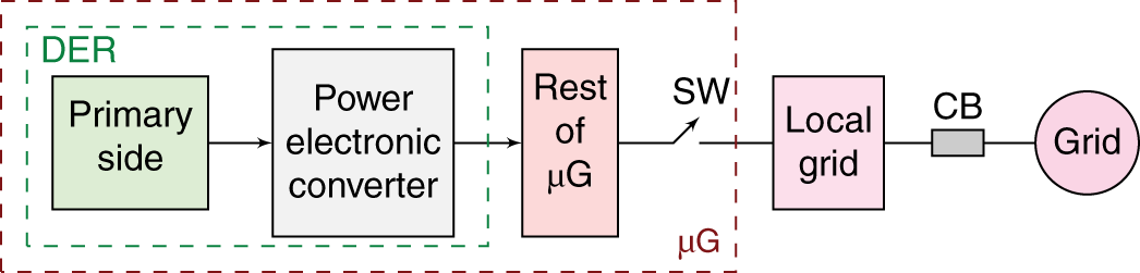
Figure I.1 General structure of a DER in a  G interfaced with the local grid.
I.4.1 Primary Side
The Primary Side of the DER may generally be one of the following cases.
- Renewable: Sun, wind, water, etc., e.g. PV panels, or a wind turbine and its generator, or a micro hydro turbine and its generator.
- Nonrenewable: Diesel, gas, etc., e.g. a micro-turbine and its generator.
- Storage: Battery.
- Load: Motor load, rectifier load, etc.
I.4.2 Power Electronic Converter (PEC)
Responsibilities of the PEC may be listed as follows.
- Shaping the power: Converting one form to another, e.g. dc to ac.
- Controlling the amount and flow of the power.
- Maintain the power quality at the both points of ac and ac interconnections.
- Provide ancillary services to the grid, for example, reactive power support, frequency response, and power quality improvement.
- Reducing penetration of disturbances from one side to other.
- Ride through the transient grid faults and support the grid.
The PEC is an interface between the source side (primary source) of the system to the grid side. It is responsible for making this interface efficient and strong. It must be able to minimize the adverse impacts of source side disturbances on the grid side and also to minimize the adverse impacts of grid side disturbances on the source side. Source side disturbances are those such as fast and unexpected changes in the input power due to intermittent nature of the renewable source.8 Grid side disturbances are those such as grid voltage faults, distortions, and its frequency swings. In a more effective scenario, the DER provides grid-supporting and grid-stabilizing functions such as reactive power support and inertial response to reduce the grid transients.
I.4.3 Some Common PEC Topologies
- Single-stage converter: Used in some PV, battery, and FC applications (Figure I.2).
Inverter9 (single-phase or three-phase) is often a voltage source converter (VSC) where its dc side is a voltage. Therefore, a capacitor is used to support the dc side voltage. Output Filter is responsible for smoothing the switching ripples and noises. In order to minimize losses, it should avoid (or minimize) using dissipative elements (such as resistors). Inductors and capacitors are used.
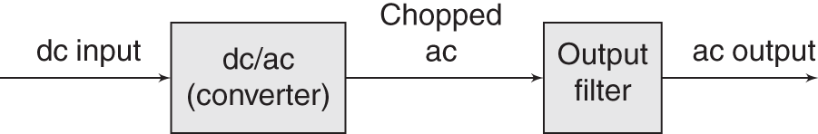
Figure I.2 Single-stage power electronic converter.
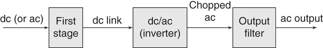
Figure I.3 Double-stage power electronic converter.
- Double-stage converter: Widely used in various applications (Figure I.3).
First Stage Converter is a dc/dc converter or simply a dc converter in PV applications. In this case, its job is normally to boost or buck the voltage and also to perform maximum power point tracking (MPPT). In Wind and Micro-turbine applications, it is an ac/dc converter (or rectifier) to convert an ac variable to dc. The dc converter allows the possibility of high-frequency galvanic isolation between the source side and the grid side as well.
Two-stage topology breaks down the control objectives so they can be addressed more efficiently by the two converters. It, however, requires more hardware which means higher cost and also lower total efficiency. The control objectives are basically the same as discussed above with the addition of controlling the dc link variable. dc Link is a capacitor (in a VSC).
- Multi-stage converters are also available. But the most popular ones are one- and two-stage converters. In some two-stage topologies, the first-stage converter already provides a rectified ac current and the inverter, operating at the switching frequency equal to the mains frequency, simply unfolds it. This approach has been used in some microinverter PV applications [12].
Some DERs use a low-frequency transformer (after the output is generated) to adjust the generated voltage level to the grid level. Low-frequency transformers are bulky and not very efficient and the advanced converters avoid them by integrating their function inside the converter.
I.5 Objectives and Scope of this Book
This book's overall objective is to bridge the gap between the power and the control aspects of a DER application. The power domain includes the primary source; the converter including its possible multiple stages, its dc link and its filters; the ![]() G; and the grid. The control part consists of the entire control system on the DER that controls the interaction of the DER with the rest of the system.
G; and the grid. The control part consists of the entire control system on the DER that controls the interaction of the DER with the rest of the system.
The book approaches its objective by deriving simple yet efficient models that describe the power and the control. The emphasis is placed on deriving models that lend themselves well to analysis and design. After deriving the models, the control objectives and specifications are comprehensively and clearly formulated. Finally, optimal and robust controllers are designed to address them.
The book reviews the fundamentals of power electronics including the introduction of the main power electronic elements, introduction of major converters mainly the VSC, and derivation of switching and control models for such converters. In addition to that, the control theory principles in both classical Laplace domain and in modern state space time domain are reviewed and some advanced optimal control design methods are explained which will form the basis for subsequent DER control designs.
The main body of the text is devoted to system analysis and control design of DERs. In order to respect the learning curve of the readers, the book starts off with simple cases where the control models and control objectives are not much demanding. The reader is walked through the analysis and design stages gradually while more and more control objectives are pulled in and addressed. Toward the end of the book, the reader will have a deep understanding of the full requirements pertaining to a desirable interaction of a DER with the grid. Advanced topics such as fault ride-through, grid support, weak grid conditions, grid forming versus grid following controllers, and inertial response are mathematically formulated and addressed.
Exercises
- I.1 Why most of the power plants are built in remote areas?
- I.2 What are the main reasons for building large interconnected power systems?
- I.3 Find out the typical voltage levels at the terminals of synchronous generators (before stepping up using transformers), standard transmission voltage levels, sub-transmission voltage levels, and the common distribution voltage levels.
- I.4 Explain why it is required to increase the voltage level in order to transmit the power over a long distance.
- I.5 Synchronous machine is widely used for generating electricity at bulk level. Explain principles of operation of this machine and its advantages as a generator.
- I.6 Induction (asynchronous) machine is widely used in industrial motor applications. Explain principles of operation of this machine and its advantages as a motor.
- I.7 When a
 G is to transition from standalone (SA) to grid-connected (GC) mode, what is the main condition before the connection switch can be safely closed?
 - I.8 Discuss power quality aspects of a DER in GC operation.
- I.9 Discuss power quality aspects of a DER in SA operation.
- I.10 An electronically interfaced load (also called an active load) uses a converter to connect to the grid. The converter can adjust the actual voltage across the load terminals. It can also modify the PF of the load. Discuss how such a load can participate in grid functions (such as voltage and frequency support).
- I.11 A hybrid dc/ac system has both of these two electricity lines available. A simple example is shown in Figure I.4 where two DERs share a dc bus. An inverter interfaces the dc bus with the ac bus. Multiple dc and ac components (loads, generators, etc.) may be interfaced to this system.
- Assume that Resource 1 is a solar PV, and Resource 2 is a battery storage. Discuss a sound operating scenario for this system. For example, the maximum energy is harvested from the PV and the battery is used to balance the generation versus consumption. Discuss two cases where the ac grid is or is not present.
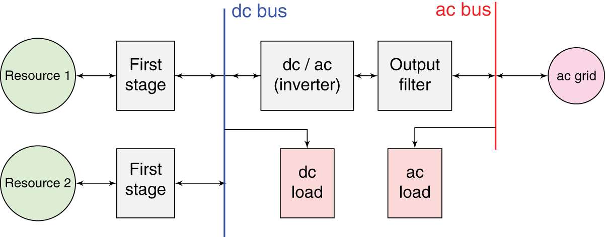
Figure I.4 A hybrid dc/ac energy system topology.
- Assume that it is desired to have a 6 kW solar PV system. How many solar panels are required? How much area is needed? (Hint: Assume that the used solar panel technology generates 300 W and its area dimensions are 1 m into 2 m.)
- Assume that the average dc load is 0.5 kW and the average ac load is 1.5 kW over 24 hours. Also, assume that you have 10 hours of sunlight per day at your location. Determine the size of battery (in terms of kW and kWh) such that the combination of PV and battery can sustain the loads in the absence of grid.
- Assume that Resource 1 is a solar PV, and Resource 2 is a battery storage. Discuss a sound operating scenario for this system. For example, the maximum energy is harvested from the PV and the battery is used to balance the generation versus consumption. Discuss two cases where the ac grid is or is not present.
References
- 1 Greatest engineering achievements of the
 century. http://www.greatachievements.org/. Accessed: 2018-17-01.
 - 2 U.S. Energy Information Administration. http://www.eia.gov. Accessed: 2017-06-08.
- 3 U.S. Energy Information Administration. U.S. energy-related carbon dioxide emissions, 2018. https://www.eia.gov/environment/emissions/carbon/pdf/2018_co2analysis.pdf. Accessed: 2020-06-01.
- 4 National Renewable Energy Laboratory. Solar energy basics: “that's because more energy from the sun falls on the earth in one hour than is used by everyone in the world in one year”. https://www.nrel.gov/workingwithus/re-solar.html. Accessed: 2017-06-08.
- 5 National Renewable Energy Laboratory. U.S. solar radiation resource maps: atlas of the solar radiation data manual for flat-plate and concentrating collectors. http://rredc.nrel.gov/solar/old_data/nsrdb/1961-1990/redbook/atlas/. Accessed: 2017-06-08.
- 6 Nikos Hatziargyriou. Microgrids: architectures and control. John Wiley & Sons, 2014.
- 7 IEEE standard for interconnection and interoperability of distributed energy resources with associated electric power systems interfaces. IEEE Std 1547-2018 (Revision of IEEE Std 1547-2003), pages 1–138, 2018.
- 8 Frede Blaabjerg, Zhe Chen, and Soeren Baekhoej Kjaer. Power electronics as efficient interface in dispersed power generation systems. IEEE Transactions on Power Electronics, 19(5):1184–1194, 2004.
- 9 Benjamin Kroposki, Christopher Pink, Richard DeBlasio, Holly Thomas, Miguel Simo es, and Pankaj K Sen. Benefits of power electronic interfaces for distributed energy systems. IEEE Transactions on Energy Conversion, 25(3):901–908, 2010.
- 10 Rob Cuzner Does DC distribution make sense? IEEE Electrification Magazine, 4(2), 2016.
- 11 Roshan Sharma and Masoud Karimi-Ghartemani. Addressing abrupt PV disturbances, and mitigating net load profile's ramp and peak demands, using distributed storage devices. Energies, 13(5):1024, 2020.
- 12 Haibing Hu, Souhib Harb, Nasser Kutkut, Issa Batarseh, and Z John Shen. A review of power decoupling techniques for microinverters with three different decoupling capacitor locations in PV systems. IEEE Transactions on Power Electronics, 28(6):2711–2726, 2012.
Notes
- 1 About 34% from natural gas, 30% from coal, 20% nuclear, 15% renewable (hydro, wind, biomass, solar, geothermal), and 1% others.
- 2 About 70% of which came from coal and 30% from natural gas power plants. The
 emission caused by the electricity generation was about 35% of the total energy-related emission.
 - 3 The numbers for 2018 are as follows [3]. Natural-gas:
 kWh of production,
  kg of
kg of  emission. Coal:
  kWh of production,
  kg of
kg of  emission.
 - 4 Renewable energy is an energy that is collected from a renewable source, which is naturally replenished on a human timescale.
- 5 Micro hydro generators convert the kinetic energy of the natural flow of water to electricity. They exist in the power range of 5–100 kW. Smaller installations are called pico hydro.
- 6 Microturbines are small (25–500 kW) generators that use a gas-fired combustion engine with an electric generator. They produce high-frequency ac electricity (in the frequency range of 1–2 kHz). Diesel generators (or diesel gensets) are found in wide power ranges and various types of fuels. Diesel generating sets are used in places without connection to a power grid, or as emergency backup power-supply (when grid is unavailable), as well as for more complex applications such as peak load shaving, grid support, and export to the power grid.
- 7 Loads that can have an active role in the system either through using a power electronic converter and/or a demand response strategy.
- 8 The PV power can experience large and swift changes when the solar irradiation changes quickly [11].
- 9 We use the terms “inverter” and “converter” interchangeably. However, to be precise, inverter is used when the power flows from dc to ac. When the power flows from ac to dc, it is specifically called “rectifier.” Converter is a general term and can include both directions of power flow.