Chapter 18, “ATM Wide-Area Networking (WAN) and MPOA,” discussed the underlying technology for ATM WAN networks and their underlying components. This chapter will discuss some recommendations and guidelines to follow to document an ATM wide-area network (WAN).
Most networking discussions today include the topic of documentation at some point, whether the mention is a statement advising that you should document your network assets or a statement advising that network documentation is a good tool to have when troubleshooting a network issue. The challenge is what network information should be documented, reviewed, and analyzed for potential network-related issues.
Network documentation should be both easy to complete and easy to understand. In an effort to make the network documentation process easier to manage for ATM WAN implementations, templates have been prepared and presented here for use. These templates are preceded by relevant console commands, a case study, and a sample completed template serving as a guide.
NOTE
Network documentation is a living process and not a single event. It is important to have clear and simple documentation templates so that the WAN staff will be committed to maintaining the documentation, preserving its value. Out-of-date documentation, if used and trusted, can be dangerous. Documentation that is not trusted is useless and brings no value to the organization.
The templates presented here are also available electronically on the Cisco Press Web site (www.ciscopress.com/1587050390).
You can approach ATM WAN documentation from two perspectives: from the individual site or from the overall WAN view. Both perspectives will be demonstrated here with supporting templates.
An introduction or case study network diagram will precede each template with suggestions regarding template completion. These templates are not all encompassing, nor are they designed to be. Rather, these templates are designed to help the consultant, engineer, or anyone involved with a network, gather the vital information pertaining to a network and its related segments.
A naming convention, or scheme, should be employed in any network for which you are responsible. A naming convention should grow as the network grows. Naming conventions should be developed so that the network documentation is easy to prepare, thus making network maintenance and troubleshooting easier for the user. For example, a network engineer new to the company's operations would be more able to recognize the function and purpose of a device named HQ_7500Router_WAN than the same device referred to as Sprint Router.
NOTE
Some would view such a descriptive naming convention as a security concern. Like so many things, tradeoffs are involved: descriptive naming versus security. These tradeoffs need to be addressed prior to a naming convention. In some instances, the use of internal codes is used, satisfying both network management and security concerns.
A good convention scheme would incorporate the geographic location of the device. A naming convention following this scheme would be designed as follows:
Geographic-location_Network-Device | Division_Network-Device
For example, an ATM WAN edge-router located at an organization's corporate headquarters could be named in one of the following fashions:
Chicago_WANRouter
HQ_WANRouter
This example reflects an ATM WAN router located at corporate headquarters, in this case, located in Chicago, Illinois.
A naming convention should be easy to use; however, one naming convention cannot work with every network. Generic conventions can be useful. The idea behind generic naming conventions is that if someone else looks at your network documentation, that person can easily determine the topology.
This same naming convention can be globally deployed and supported across the organization by the use of a domain name server (DNS). By deploying the naming scheme across the domain with DNS, administration and inventory is simpler to manage. Troubleshooting is also facilitated in a more manageable fashion than without the use of a naming standard.
For example, the following trace route command would not be of much help to an engineer without the names.
 1   WashingtonDC.MCIRouter.Engineering [207.69.220.81]
 2   cisco-f0-1-0.norva3.mindspring.net [207.69.220.65]
 3   s10-0-1.vienna1-cr3.bbnplanet.net [4.1.5.237]
 4   p4-2.vienna1-nbr2.bbnplanet.net [4.0.1.133]
 5   p4-0.washdc3-br2.bbnplanet.net [4.0.1.97]
 6   p3-0.washdc3-br1.bbnplanet.net [4.24.4.145]
 7   p2-0.chcgil1-br2.bbnplanet.net [4.24.6.93]
 8   p4-0.chcgil1-br1.bbnplanet.net [4.24.5.225]
 9   so-4-1-0.chcgil2-br1.bbnplanet.net [4.24.9.69]
10   p1-0.chcgil2-cr11.bbnplanet.net [4.24.6.22]
11   p7-1.paloalto-nbr1.bbnplanet.net [4.24.6.98]
12   p1-0.paloalto-cr1.bbnplanet.net [4.0.6.74]
13   h1-0.cisco.bbnplanet.net [4.1.142.238]
14   pigpen.cisco.com [192.31.7.9]
15   www.cisco.com [198.133.219.25]
Table 19-1 can be used to document a single ATM site, where the site of discussion is not concerned with the WAN as a whole, but rather its view into the WAN.
Table 19-1. ATM WAN Site Information
| Site Name | Mnemonic | ||||||||||||||||||
|---|---|---|---|---|---|---|---|---|---|---|---|---|---|---|---|---|---|---|---|
| ATM Access Bandwidth | ATM Access Ckt ID | ||||||||||||||||||
| Access Carrier | Local Access Ckt ID | Channels | |||||||||||||||||
| Intfc/ VPI/VCI | Term. Network Address | Term. Site Name | Term. Site Mnemonic | Term. ATM Circuit ID | Term. ATM Access Bandwidth | SCR | PCR | CoS | |||||||||||
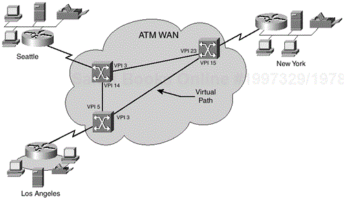
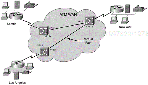
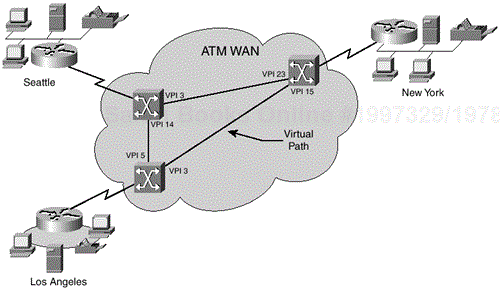
Figure 19-1 will be used to complete the associated documentation example. Only the virtual path identifiers (VPIs) are indicated within the drawing because the accompanying form will reflect multiple virtual channel identifiers (VCIs).
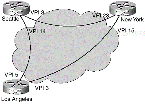
Figure 19-1 is a somewhat detailed network diagram of a 3-node ATM WAN. Although diagrams like this are useful in certain situations, the amount of time involved in their construction could be best spent otherwise. A simpler network diagram (Figure 19-2) is just as useful as the previous diagram, without the additional detail that could clutter the representation. The simpler form also takes less time to prepare.
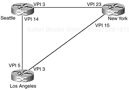
The previous diagram can also be illustrated as shown in Figure 19-3.
NOTE
Regarding network diagrams, two methods are generally used to illustrate a network topology:
Topology with the WAN cloud
End nodes and virtual circuits only
Each method has a distinct advantage. The first method, topology with the WAN cloud, is useful for illustrative purposes, such as inclusion within presentations. However, the WAN cloud becomes cluttered and illegible quickly as more end nodes are added to the WAN. This is especially true if multiple fully or partially meshed virtual circuits are available. The second method, end nodes and virtual circuits only, is useful from a network topology standpoint and is useful for illustrating client network components (such as end nodes and virtual circuits). Both methods of network diagramming are useful, and care should be taken when choosing which methodology will be used. For the purposes of the following templates, both methods will be illustrated.
This network would be documented from each site in Tables 19-2, 19-3, and 19-4.
Table 19-2. ATM WAN Template for Example 1 (Seattle)
| Site Name | Seattle | Mnemonic | SEA_WAN | |||||||||||||
|---|---|---|---|---|---|---|---|---|---|---|---|---|---|---|---|---|
| ATM Access Bandwidth | 1536 | ATM Access Ckt ID | ||||||||||||||
| Access Carrier | Local Access Ckt ID | Channels | 1 to 24 | |||||||||||||
| Intfc/ VPI/VCI | Term.Network Address | Term. Site Name | Term. Site Mnemonic | Term. ATM Circuit ID | Term. ATM Access Bandwidth | SCR | PCR | CoS | ||||||||
| 2/14/1 | L.A. | WAN_LA | 1536 | 768 | 768 | CBR | ||||||||||
| 2/3/1 | N.Y. | WAN_NY | 1536 | 384 | 384 | CBR | ||||||||||
| 2/3/2 | N.Y. | WAN_NY | 1536 | 768 | VBRnrt | |||||||||||
Table 19-3. ATM WAN Template for Example 1 (New York)
| Site Name | New York | Mnemonic | WAN_NY | ||||||||||||||
|---|---|---|---|---|---|---|---|---|---|---|---|---|---|---|---|---|---|
| ATM Access Bandwidth | 1536 | ATM Access Ckt ID | |||||||||||||||
| Access Carrier | Local Access Ckt ID | Channels | 1 to 24 | ||||||||||||||
| Intfc/ VPI/VCI | Term. Network Address | Term. Site Name | Term. Site Mnemonic | Term. ATM Circuit ID | Term. ATM Access Bandwidth | SCR | PCR | CoS | |||||||||
| 2/23/1 | Seattle | WAN_SEA | 1536 | 384 | 384 | CBR | |||||||||||
| 2/15/1 | L.A. | WAN_LA | 1536 | 384 | 384 | VBRnrt | |||||||||||
| 2/15/5 | L.A. | WAN_LA | 1536 | 768 | UBR | ||||||||||||
Table 19-4. ATM WAN Template for Example 1 (Los Angeles)
| Site Name | Los Angeles | Mnemonic | WAN_LA | ||||||||||||||
|---|---|---|---|---|---|---|---|---|---|---|---|---|---|---|---|---|---|
| ATM Access Bandwidth | 1536 | ATM Access Ckt ID | |||||||||||||||
| Access Carrier | Local Access Ckt ID | Channels | 1 to 24 | ||||||||||||||
| Intfc/ VPI/VCI | Term. Network Address | Term. Site Name | Term. Site Mnemonic | Term. ATM Circuit ID | Term. ATM Access Bandwidth | SCR | PCR | CoS | |||||||||
| 3/5/2 | Seattle | WAN_Sea | 1536 | 768 | 768 | CBR | |||||||||||
| 3/3/17 | N.Y. | WAN_NY | 1536 | 384 | 384 | VBRnrt | |||||||||||
These three forms provide each site a view of other sites to which they are directly interconnected. For example, the New York form does not reflect the interconnection between Los Angeles and Seattle because New York is not concerned with this interconnection; it is not in its view of the WAN.
Three Cisco IOS commands can be primarily used to collect ATM WAN topology information:
show atm vp
show atm vc
show atm map
The show atm map IOS command will be discussed in the next section, “Global ATM WAN Documentation.”
The show atm vp command is used to display the ATM layer connection information about the virtual path:
show atm vp

show atm vp interface {atm | atm-p} card/subcard/port [.vpt#] [vpi vci]

show atm vp [cast-type cast-type] [conn-type conn-type]
[interface {atm | atm-p} card/subcard/port[.vpt#]]

show atm vp traffic [interface {atm | atm-p} card/subcard/port [.vpt#] [vpi vci]]
Table 19-6. show atm vp Syntax and Description
| Syntax | Description |
|---|---|
| Card/subcard/port | Card, subcard, and port number for the interface |
| .vpt# | Virtual path tunnel identifier |
| vpi vci | Virtual path identifier and virtual channel identifier to display |
| cast-type | Cast type as point-to-multipoint (p2mp) or point-to-point (p2p) |
| conn-type | Connection type as pvc, soft-vc, or svc |
| traffic | Virtual channel cell traffic |
The following code is displayed from show atm vp output:
JLBalSwitch# show atm vp

Interface    VPI     Type    X-Interface  X-VPI     Status
ATM3/1/1     1       SVP     ATM3/1/2     200       UP
ATM3/1/1     2       SVP     ATM3/1/2     201       UP
ATM3/1/1     3       SVP     ATM3/1/2     202       UP
ATM3/1/2     200     SoftVP  ATM3/1/1     1         UP
ATM3/1/2     201     SoftVP  ATM3/1/1     2         UP
ATM3/1/2     202     SoftVP  ATM3/1/1     3         UP
ATM3/1/2     255     SoftVP  NOT CONNECTED
The following code is displayed from show atm vp output for ATM 3/1/1:
JLBalSwitch# show atm vp interface atm 3/1/1

Interface    VPI    Type  X-Interface     X-VPI     Status
ATM3/1/1     1       SVP     ATM3/1/2     200       UP
ATM3/1/1     2       SVP     ATM3/1/2     201       UP
ATM3/1/1     3       SVP     ATM3/1/2     202       UP
The following table describes the fields shown in the show atm vp output display.
Table 19-7. show atm vp Interface ATM Field Descriptions
| Field | Description |
|---|---|
| Interface | Displays the card, subcard, and port number of the ATM interface |
| VPI/VCI | Displays the number of the virtual path identifier and the virtual channel identifier |
| Status | Displays the type of interface for the specified ATM interface |
| Time-since-last-status-change | Displays the time elapsed since the last status change |
| Connection-type | Displays the type of connection for the specified ATM interface |
| Cast-type | Displays the type of cast for the specified ATM interface |
| Usage-Parameter-Control (UPC) | Displays the state of the UPC |
| Number of OAM-configured connections | Displays the number of connections configured by OAM |
| OAM-configuration | Displays the state of the OAM configuration: enabled or disabled |
| OAM-states | Displays the status of the OAM state: applicable or not applicable |
| OAM Loopback-Tx-Interval | Displays the OAM loopback transmit interval |
| Cross-connect-interface | Displays the cross-connect interface number |
| Cross-connect-VPI | Displays the cross-connect VPI number |
| Cross-connect-UPC | Displays the cross-connect UPC status |
| Cross-connect OAM-configuration | Displays the configuration of the OAM in the cross-connect half-leg |
| Cross-connect OAM-state | Displays the state of the OAM cross-connect half-leg |
| OAM-Loopback-Tx-Interval | Displays the OAM loopback transmit interval |
| Rx cells/Tx cells | Displays the number of cells transmitted and received |
Table 19-7. Frame Relay Standard Frame Field Descriptions
| Field | Description |
|---|---|
| Rx connection-traffic-table-index | Displays the receive connection-traffic-table-index |
| Rx service-category | Displays the receive service category |
| Rx pcr-clp01 | Displays the receive peak cell rate for clp01 cells (kbps) |
| Rx scr-clp01 | Displays the receive sustained cell rate for clp01 cells (kbps) |
| Rx mcr-clp01 | Displays the receive minimum cell rate for clp01 cells (kbps) |
| Rx cdvt | Displays the receive cell delay variation tolerance |
| Rx mbs | Displays the receive maximum burst size |
| Tx connection-traffic-table-index | Displays the transmit connection-traffic-table-index |
| Tx service-category | Displays the transmit service category |
| Tx pcr-clp01 | Displays the transmit peak cell rate for clp01 cells (kbps) |
| Tx scr-clp01 | Displays the transmit sustained cell rate for clp01 cells (kbps) |
| Tx mcr-clp01 | Displays the transmit minimum cell rate for clp01 cells (kbps) |
| Tx cdvt | Displays the transmit cell delay variation tolerance |
| Tx mbs | Displays the transmit maximum burst size |
The show atm vc command is used to display the ATM layer connection information:
show atm vc

show atm vc interface {atm | atm-p} card/subcard/port [.vpt#] [vpi vci]

show atm vc [cast-type cast-type] [conn-type conn-type]
[interface {atm | atm-p} card/subcard/port[.vpt#]]

show atm vc traffic [interface {atm | atm-p} card/subcard/port [.vpt#] [vpi vci]]
Table 19-8. show atm vc Syntax and Description
| Syntax | Description | |||
|---|---|---|---|---|
| card/subcard/port | Displays the card, subcard, and port number for the interface | |||
| .vpt# | Specifies the virtual path tunnel identifier to display | |||
| vpi vci | Specifies the virtual path identifier and virtual channel identifier to display | |||
| Detail | Displays the Rx cell drops and queued-cells for all VCs on a given interface | |||
| cast-type | Specifies the cast type as multipoint-to-point (mp2p), point-to-multipoint (p2mp), or point-to-point (p2p) | |||
| conn-type | Specifies the connection type as pvc, soft-vc, svc, or pvc | |||
| traffic | Displays the virtual channel cell traffic |
The following code is displayed from show atm vc output:
JLBalSwitch# show atm vc
Switch# show atm vc
Interface    VPI   VCI    Type    X-Interface  X-VPI  X-VCI  Encap  Status
ATM0/1/0     0     5      PVC     ATM0         0      52     QSAAL  UP
ATM0/1/0     0     16     PVC     ATM0         0      32     ILMI   UP
ATM0/1/0     0     18     PVC     ATM0         0      73     PNNI   UP
ATM0/1/1     0     5      PVC     ATM0         0      53     QSAAL  DOWN
ATM0/1/1     0     16     PVC     ATM0         0      33     ILMI   DOWN
ATM0/1/2     0     5      PVC     ATM0         0      54     QSAAL  DOWN
ATM0/1/2     0     16     PVC     ATM0         0      34     ILMI   DOWN
ATM0/1/3     0     5      PVC     ATM0         0      55     QSAAL  UP
ATM0/1/3     0     16     PVC     ATM0         0      35     ILMI   UP
ATM1/0/0     0     5      PVC     ATM0         0      56     QSAAL  UP
ATM1/0/0     0     16     PVC     ATM0         0      36     ILMI   UP
ATM1/0/1     0     5      PVC     ATM0         0      57     QSAAL  DOWN
ATM1/0/1     0     16     PVC     ATM0         0      37     ILMI   DOWN
ATM1/0/2     0     5      PVC     ATM0         0      58     QSAAL  DOWN
ATM1/0/2     0     16     PVC     ATM0         0      38     ILMI   DOWN
ATM1/0/3     0     5      PVC     ATM0         0      59     QSAAL  UP
ATM1/0/3     0     16     PVC     ATM0         0      39     ILMI   UP
ATM1/0/3     0     18     PVC     ATM0         0      72     PNNI   UP
ATM1/1/0     0     5      PVC     ATM0         0      60     QSAAL  DOWN
ATM1/1/0     0     16     PVC     ATM0         0      40     ILMI   DOWN
ATM1/1/1     0     5      PVC     ATM0         0      61     QSAAL  DOWN
ATM1/1/1     0     16     PVC     ATM0         0      41     ILMI   DOWN
Table 19-9. show atm vc Field Descriptions
| Field | Description |
|---|---|
| Interface | Displays the card, subcard, and port number of the specified ATM interface |
| VPI | Displays the number of the virtual path identifier |
| VCI | Displays the number of the virtual channel identifier |
| Type | Displays the type of interface for the specified ATM interface |
| X-Interface | Displays the card, subcard, and port number of the cross-connected value for the ATM interface |
| X-VPI | Displays the number of the cross-connected value of the virtual path identifier |
| X-VCI | Displays the number of the cross-connected value of the virtual channel identifier |
| Encap | Displays the type of connection on the interface |
| Status | Displays the current state of the specified ATM interface |
The following table describes the fields shown in the show atm vc output display.
Table 19-10. show atm vc Interface ATM Field Descriptions
| Field | Description |
|---|---|
| Interface | Displays the card, subcard, and port number of the ATM interface |
| VPI/VCI | Displays the number of the virtual path identifier and the virtual channel identifier |
| Status | Displays the type of interface for the specified ATM interface |
| Time-since-last-status-change | Displays the time elapsed since the previous status change |
| Connection-type | Displays the type of connection for the specified ATM interface |
| Cast-type | Displays the type of cast for the specified ATM interface |
| Packet-discard-option | Displays the state of the packet-discard option: enabled or disabled |
| Usage-Parameter-Control (UPC) | Displays the state of the UPC |
| Wrr weight | Weighted round-robin weight |
| Number of OAM-configured connections | Displays the number of connections configured by OAM |
| OAM-configuration | Displays the state of the OAM configuration: enabled or disabled |
| OAM-states | Displays the status of the OAM state: applicable or not applicable |
| Cross-connect-interface | Displays the card, subcard, and port number of the cross-connected ATM |
| Cross-connect-VPI | Displays the number of the cross-connected virtual path identifier |
| Cross-connect-VCI | Displays the number of the cross-connected virtual channel identifier |
| Cross-connect-UPC | Displays the state of the cross-connected UPC: pass or not pass |
| Cross-connect OAM-configuration | Displays the state of the cross-connected OAM configuration: enabled or disabled |
| Cross-connect OAM-state | Displays the status of the cross-connected OAM state: applicable or not applicable |
| Encapsulation | Displays the encapsulation type |
| Threshold Group/Cells queued | Displays the threshold group number and number of cells queued |
| Rx cells/Tx cells | Displays the number of cells transmitted and received |
| Tx Clp0/Tx Clp1 | Displays the number of CLP=0 and CLP=1 cells transmitted |
| Rx Clp0/Rx Clp1 | Displays the number of CLP=0 and CLP=1 cells received |
| Rx Upc Violations | Displays the number of UPC violations detected in the receive cell stream |
| Rx cell drops | Displays the number of cells received and then dropped |
| Rx pkts | Displays the number of packets received |
| Rx pkt drops | Displays the number of packets dropped |
| RxClp0q full drops | Displays the number of CLP=0 cells received and then dropped for exceeding the input queue size |
| Rx Clp1 qthresh drops | Displays the number of CLP=1 cells received and then dropped for exceeding the discard threshold of the input queue |
| Rx connection-traffic-table-index | Displays the receive connection-traffic-table-index |
| Rx service-category | Displays the receive service category |
| Rx pcr-clp01 | Displays the receive peak cell rate for clp01 cells (kbps) |
| Rx scr-clp01 | Displays the receive sustained cell rate for clp01 cells (kbps) |
| Rx mcr-clp01 | Displays the receive minimum cell rate for clp01 cells (kbps) |
| Rx cdvt | Displays the receive cell delay variation tolerance |
| Rx mbs | Displays the receive minimum burst size |
| Tx connection-traffic-table-index | Displays the transmit connection-traffic-table-index |
| Tx service-category | Displays the transmit service category |
| Tx pcr-clp01 | Displays the transmit peak cell rate for clp01 cells (kbps) |
| Tx scr-clp01 | Displays the transmit sustained cell rate for clp01 cells (kbps) |
| Tx mcr-clp01 | Displays the transmit minimum cell rate for clp01 cells (kbps) |
| Tx cdvt | Displays the transmit cell delay variation tolerance |
| Tx mbs | Displays the transmit minimum burst size |
| Crc error | Displays the number of cyclic redundancy check errors |
| Sar Timeouts | Displays the number of segmentation and reassembly timeouts |
| OverSizedSDUs | Displays the number of oversized service data units |
| BufSzOvfl | Displays the number of buffer size overflows |
The following code shows the output display for interface ATM 1/0/0 with and without the detail keyword, showing the Rx-cel-drops and the Rx-queued-cells:
JLBalSwitch# show atm vc traffic interface atm 1/0/0

Interface         VPI  VCI   Type      rx-cell-cnts     tx-cell-cnts
ATM-P1/0/0        0    32    PVC               1                0
ATM-P1/0/0        0    33    PVC               0                0
ATM-P1/0/0        0    34    PVC               0                0
ATM-P1/0/0        0    35    PVC               0                0
ATM-P1/0/0        0    37    PVC               0                0
ATM-P1/0/0        0    39    PVC               0                0
ATM-P1/0/0        0    48    PVC               0                0

JLBalSwitch# show atm vc traffic interface atm 1/0/0 detail

Interface         VPI  VCI   Type      rx-cell    tx-cell rx-cell-drop rx-cell-qued
ATM-P1/0/0        0    32    PVC             1          0           0          0
ATM-P1/0/0        0    33    PVC             0          0           0          0
ATM-P1/0/0        0    34    PVC             0          0           0          0
ATM-P1/0/0        0    35    PVC             0          0           0          0
ATM-P1/0/0        0    37    PVC             0          0           0          0
ATM-P1/0/0        0    39    PVC             0          0           0          0
ATM-P1/0/0        0    48    PVC             0          0           0          0
A global ATM WAN document is one that provides an overall, or global, view of the ATM WAN. This document provides information regarding interconnectivity between each node of the wide-area network. A global document can be used to represent just Layer 2 (VPI/VCI) information, Layer 3 network [addressing] information, or some combination of the two. The decision rests with the individual, or organization, for which the document is intended. The goal is for network documentation to be useful, not a burden.
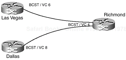
The following three-node network (Figures 19-4 and 19-5) will be used to demonstrate how a Layer 2 and Layer 3 global template (Tables 19-12 and 19-13) can be completed. Provided here are both a network diagram and the show atm map output from the head-end node—in this case, Richmond.
The show atm map command is used to display the list of all configured ATM static maps to remote hosts on an ATM network.
The following code is sample output from the show atm map command for a multipoint connection:
JLBalSwitch# show atm map

Map list atm_pri: PERMANENT
ip 4.4.4.4 maps to NSAP CD.CDEF.01.234567.890A.BCDE.
  F012.3456.7890.1234.12, broadcast,
Aal5mux, multipoint connection up, VC 6
ip 4.4.4.6 maps to NSAP DE.CDEF.01.234567.890A.BCDE.
  F012.3456.7890.1234.12, broadcast,
Aal5mux, connection up, VC 15, multipoint connection up, VC 6

Map list atm_ipx: PERMANENT
ipx 1004.dddd.dddd.dddd maps to NSAP DE.CDEF.01.234567.890A.
  BCDE.F012.3456.7890.1234.12,
broadcast, aal5mux, multipoint connection up, VC 8
ipx 1004.cccc.cccc.cccc maps to NSAP CD.CDEF.01.234567.890A.
  BCDE.F012.3456.7890.1234.12,
Broadcast, aal5mux, multipoint connection up, VC 8

Map list atm_apple: PERMANENT
AppleTalk 62000.5 maps to NSAP CD.CDEF.01.234567.890A.BCDE.F012.
  3456.7890.1234.12,
Broadcast, aal5mux, multipoint connection up, VC 4
appletalk 62000.6 maps to NSAP DE.CDEF.01.234567.890A.BCDE.F012.
  3456.7890.1234.12,
broadcast, aal5mux, multipoint connection up, VC 4
Table 19-11 describes the fields shown in the show atm map output display.
Table 19-11. show atm map Multipoint Field Descriptions
| Field | Description |
|---|---|
| Map list | Name of map list |
| PERMANENT | Map entry that was entered from configuration; it was not entered automatically by a process |
| Protocol address maps to VC x or protocol address maps to NSAP | Name of protocol, the protocol address, and the virtual circuit descriptor (VCD) or NSAP to which the address is mapped |
| Broadcast | Indication of pseudo-broadcasting |
| aal5mux | Indication of the encapsulation used, a multipoint or point-to-point virtual connection, and the number of the virtual connection |
| Multipoint connection up | Indication that this is a multipoint virtual connection |
| VC 6 | Number of the virtual connection |
| Connection up | Indication a point-to-point virtual connection |
Table 19-12. ATM (Layer 2) Documentation
| Origination (Site A) | Termination (Site B) | ||||||||
|---|---|---|---|---|---|---|---|---|---|
| Site Name | Site Ckt ID | Site Location | ATM Intfc and Port Speed | A | Site Name | Site Ckt ID | ATM Intfc and Port Speed | A | Comments |
| Richmond | ATM-Rich001 | Richmond | ATM3 1536 K | BCST VC4 | Las Vegas | ATM-Lasv0001 | ATM3 1536 K | BCST VC6 | |
| BCST VC4 | Dallas | ATM-DalT0001 | BCST VC8 | ||||||
| Las Vegas | ATM-Lasv0001 | Las Vegas | ATM2 1536 K | BCST VC6 | Richmond | ATM-Rich0001 | ATM2 1536 K | BCST VC4 | |
| Dallas | ATM-DalT0001 | Dallas | ATM2 1536L | BCST VC8 | Richmond | ATM-Rich0001 | ATM2 1536L | BCST VC4 | |
The ATM VPI/VCI documentation template (See Tables 19-14 and 19-15) can be used as a VPI/VCI Quick Reference. A quick reference sheet like this one could be attached to the router for use during troubleshooting of Layer 2 connectivity issues, especially if coordinating troubleshooting activities with the network service provider.
Figure 19-6 will be used to complete the Frame Relay DLCI Table.
Table 19-14. ATM VPI/VCI Table Example
| Site A (Origination) | Site B (Termination) | A | B |
|---|---|---|---|
| Los Angeles | New York | VPI 3 / BCST[1] | VPI 15 / BCST |
| Los Angeles | Seattle | VPI 5 / BCST | VPI 14 / BCST |
| Seattle | New York | VPI 3 / BCST | VPI 23 / BCST |
| Seattle | Los Angeles | VPI 14 / BCST | VPI 5 / BCST |
| New York | Seattle | VPI 23 / BCST | VPI 3 / BCST |
| New York | Los Angeles | VPI 15 / BCST | VPI 3 / BCST |
[1] BCST indicates that all traffic sent on this virtual path is broadcast to all configured virtual channels (VCs). | |||
The following Cisco IOS commands are used to gather pertinent ATM WAN information and in turn used to complete network documentation templates:
The show atm vp command is used to display the ATM layer connection information concerning the virtual path.
The show atm vc command is used to display the ATM layer connection information.
The show atm map command is used to display the list of all configured ATM static maps to remote hosts on an ATM network.
