In this chapter, we compare and contrast the routing protocols in use in today’s Internet: RIP, OSPF, BGP, IGRP, and Integrated IS-IS. As we have seen, routing protocols can be categorized into IGPs and EGPs. (By the way, many TCP/IP routing protocols contain the word gateway. This was the original term for what we now call a router, a network-layer switching device. Today the word gateway is used for devices that switch at higher levels of the OSI reference model: mail gateways, application-level gateways, and so on.) Internet routing protocols can also be classified according to the basic routing technology they employ: Distance Vector or link-state (Table 13.1).
Table 13.1. Classification of TCP/IP Routing Protocols. (Boldface type indicates protocols in use in the Internet.)
Protocol Type | Distance Vector | Link State |
|---|---|---|
IGPs | GGP Hello RIP IGRP | OSPF Integrated IS-IS |
EGPs | EGP BGP | IDPR |
In the sections that follow, we will describe each of the Internet’s routing protocols. Each routing protocol has to perform a basic set of activities. For example, a router has to be able to detect its neighboring routers. It also has to have a reliable way of collecting routing data and of turning this data into routing table entries. In order to better understand how the protocols work and to compare and contrast them, we will describe each protocol in terms of the following categories.
Type. Is the protocol an EGP or an IGP; does it employ Distance Vector or link-state routing technology?
Encapsulation. Does the routing protocol run directly over IP, over one of the Internet transport protocols (TCP or UDP), or directly over the data-link layer?
Path characteristics. What do the “best” paths selected by the protocol look like? For example, RIP always selects paths that go through a minimum number of routers. Other protocols can select minimum-delay paths or minimize other metrics. Still other protocols do not include a metric but allow the network administrator to indicate path preferences.
Neighbor discovery and maintenance. How does a router running the protocol discover the routers (called neighbors, or peers) with which it is to exchange routing information? How does the router discover failures in these neighbors so that it can route traffic around them when necessary?
Routing data distribution. What is the raw routing data that is distributed between routers running the protocol, and how is this distribution performed?
Route deletion. When a destination prefix becomes unreachable, how is this information propagated by the routing protocol?
Routing table calculation. How does the router calculate routing table entries from the raw routing data received from its neighbors?
Robustness/reliability. How does the protocol ensure that routing data is transmitted reliably between routers? In what other ways does the protocol try to ensure that transmission errors and hardware or software errors within the routers do not permanently impair routing?
Aggregation. How does the protocol combine routing information for a collection of prefixes, producing a routing advertisement for a single, smaller prefix?
Policy controls. In what ways can the network administrator bias the paths calculated by the protocol? For example, an ISP may wish to ensure that traffic going between two of its customers never leaves the ISP’s network. Or, the network administrator may not wish to route traffic to prefixes originating from a particular AS number.
Security. How does the protocol guard against intruders trying to disrupt protocol exchanges and/or corrupt routing data?
The development of TCP/IP and the Internet was strongly influenced by the University of California at Berkeley’s BSD UNIX project. BSD UNIX was the first widely deployed TCP/IP host implementation and still serves as the reference implementation for TCP/IP developers [264]. The work done in BSD UNIX on TCP congestion control has been one of the major factors enabling the Internet to grow to its present size. And BSD UNIX provided the Internet with its first widespread routing protocol implementation, which is still probably the most common routing protocol in use in today’s Internet: the Routing Information Protocol (RIP) [95]. RIP also is run commonly by TCP/IP hosts as a router discovery mechanism and as a way to find the best router to use for a given destination (Section 1.2). The routed program, an implementation of RIP, is shipped with all UNIX systems.
TCP/IP’s RIP is an adaptation of the XNS Routing Information Protocol [265]. Leaving the protocol mechanisms largely unchanged, the BSD networking developers made RIP multiprotocol by advertising UNIX sockaddr structures within RIP routing updates. This allowed RIP to be used not only as a TCP/IP routing protocol but also for other network stacks, such as OSI.
TCP/IP’s RIP is the classic Distance Vector protocol (Section 2.3) and is used as an IGP within the Internet. As such, RIP employs a distributed computation scheme: RIP routers cooperate by sending routing updates to their neighbors. These updates cause their neighbors to change their routing tables incrementally and to send new updates in response, causing further routing table changes. Eventually this process causes all the routers’ routing tables to converge to stable values (see Figure 13.1).
Figure 13.1. Operation of RIP. The received routing table entry having the shortest cost is installed in the router’s routing table and then rebroadcast in the router’s own RIP updates.
RIP depended on the original division of TCP/IP addresses into Class A, B, and C networks, allowing any of these networks to be split into physically contiguous, fixed-sized subnets. In order to support CIDR, a new version of RIP was developed, RIPv2. The original RIP protocol, also now called RIPv1, has the following properties.
Type: RIP is a Distance Vector IGP.
Encapsulation: RIP runs over UDP, using UDP port 520.
Path characteristics: RIP routes are based solely on hop count. To get to a particular destination, RIP routers choose the path that goes through the minimum number of routers. The maximum hop count supported by RIP is 15; destinations 16 hops or farther away are considered unreachable.
Neighbor discovery and maintenance: RIP has no neighbor discovery and maintenance procedures separate from route distribution. In particular, RIP has no way to discover one-way links.
Routing data distribution: RIP routers broadcast RIP updates to their neighbors. RIP updates list a collection of destination prefixes, together with their metrics (Figure 13.2). On receiving a RIP update from a neighbor, a RIP router decides whether to update its routing table. However, unlike OSPF, with its link-state database, and BGP, with its RIB-In, a RIP router keeps only the current best route, which is stored directly in the router’s routing table. RIP routing updates are limited to a size of 512 bytes. Each prefix entry within a RIP routing update consumes 20 bytes, limiting the number of prefixes per routing update to 25. To advertise a larger number of prefixes, multiple RIP updates are sent.
Response to changes: When a routing table in a RIP router changes, the RIP router usually will broadcast updates for the new prefix immediately, before waiting for the normal 30-second timer. These updates, called triggered updates, are caused by (a) one of the router’s interfaces becoming operational, in which case the router starts advertising the attached prefix with a cost of 1; (b) one of the router’s interfaces going inoperational, in which case the router advertises the prefix as unreachable by assigning the prefix a metric of 16; (c) a RIP update from a neighbor has modified the routing table; or (d) a routing table entry has timed out (more on this later). Triggered updates advertise only those prefixes whose cost has changed.
Routing table calculation: Prefixes belonging to directly connected network segments are always installed in the routing table with a cost of 1. The next hop for other prefixes is set equal to the RIP router advertising the smallest metric N, with the routing table cost for the prefix set to N + 1.
Robustness/reliability: A RIP router broadcasts its complete routing table every 30 seconds. If for some reason a neighbor fails to receive one of the router’s RIP update packets—for example, the packet is damaged by transmission errors or dropped due to congestion—the neighbor will probably just receive an identical update 30 seconds later.
Aggregation: RIP aggregates routing information at the boundary of a subnetted network (the collected subnets of a Class A, B, or C network). Inside the subnetted network, individual subnets are advertised separately. Outside the subnetted network, the entire subnetted network is advertised as a single prefix having a cost of 1. For example, if RIP were running in Figure 1.5, routers G–J would exchange information about the four subnets of 128.1/16, but G advertises only the single prefix 128.1/16 to the routers C and D.
Policy controls: Although not formally part of the RIP specification, most RIP implementations allow the implementation of routing policies through the configuration of routing filters. By configuring routing filters, a network administrator can control which subnets a RIP router will accept and which subnets a RIP router will advertise, usually on a per neighbor basis.
Security: RIPv1 has no provisions for security.

When a RIP router first comes up, it need not wait for 30 seconds before getting RIP updates from its neighbors. The RIP router can instead broadcast RIP request packets, asking its neighbors to immediately send their updates.
Figure 13.2 shows a packet trace of a router, 192.148.30.22, broadcasting its RIP updates. Since the router’s routing table has 355 entries, 15 consecutive RIP packets must be sent back to back. RIP’s strategy of broadcasting the entire routing table every 30 seconds is a simple, fairly robust scheme for reliably delivering routing information. However, as this trace shows, the scheme also has its problems. First, it can take a lot of consecutive update packets to transmit even a moderate-sized table: 1,000 entries would take 40 packets, utilizing an average bandwidth of 5.4 Kbits/sec (in comparison, OSPF would use only 142 bits/sec). Also, many routers cannot process a large number of back-to-back routing updates. In these situations, the receiving router usually drops the same part of the back-to-back packet sequence every time, resulting in the inability to receive certain prefixes.
Since a RIP router expects to receive routing updates continually confirming its choice of next hop, it eventually gives up on the next-hop router if updates cease to be received. After not hearing from the next hop for 90 seconds, the router will move the next hop to any neighboring router that advertises a path of equal cost. After not hearing from the next hop for 180 seconds, the routing table entry will simply be declared unreachable.
RIP routers usually implement some of the standard mechanisms for improving convergence of a Distance Vector algorithm (Section 2.3). These include triggered updates, split horizon, and infinite split horizon.
In order to support CIDR, a new version of RIP was designed, called RIPv2 [149]. By adding a mask field to each route, RIPv2 can advertise CIDR prefixes. All RIP mechanisms and convergence behaviors are maintained in RIPv2. But additional fields besides the mask are advertised with each route: a 16-bit route tag, used to group routes together for policy reasons; and a next-hop field, used to eliminate extra forwarding hops at the edge of a RIP routing domain (see the documentation of the equivalent OSPF functions, OSPF’s external route tag and forwarding address, in Section 11.6). RIPv2 also allows received RIP updates to be authenticated by including authentication information within the RIP updates [13]. RIPv2 routing updates are multicast to the address 224.0.0.9, although all RIPv2 routers can be configured to revert to broadcast in order to interoperate with RIPv1 routers.
RIP has also been modified to carry IPv6 addresses, resulting in the RIPng routing protocol for IPv6 [151].
The Open Shortest Path First (OSPF) protocol is a link-state IGP designed expressly for the Internet. OSPF was originally built as a RIP replacement, designed to provide quick convergence with only a small amount of routing control traffic, even in ASs with a large number of routers. The original proving grounds for OSPF were some of the second-level networks of the T1 NSFNET, the so-called NSF regional networks [168]. OSPF is now the recommended IGP for the Internet [85]. This is a recommendation made by the Internet Engineering Task Force (IETF). It is impossible to legislate protocol usage in the Internet, so the recommendation simply encourages all makers of Internet routers to implement the OSPF protocol.
As a link-state protocol, the core of OSPF consists of creating and maintaining a distributed replicated database, called the link-state database. As long as every OSPF router has an identical link-state database, OSPF calculates loop-free paths; most of the protocol machinery within OSPF is dedicated to keeping the database synchronized between routers. Figure 13.3 shows how OSPF operates.

Figure 13.3. Operation of the OSPF protocol. OSPF LSAs received on one interface are installed in the link-state database and flooded out the router’s other interfaces. From the link-state database, an OSPF router calculates its routing table, using Dijkstra’s Shortest Path First (SPF) algorithm.
A router running OSPF discovers its neighboring OSPF routers by multicasting OSPF Hello packets onto its directly connected network segments. After discovering a neighboring router, the router synchronizes link-state databases with the neighbor. Only then does the router advertise the connection to the neighbor in a link-state advertisement (LSA, the name OSPF uses for individual pieces of the link-state database). The router then starts the distribution of the LSA to all other routers through OSPF’s reliable flooding mechanism. Once the other routers receive this LSA, they rerun their routing calculations, which consist of Dijkstra’s SPF algorithm performed on the link-state database. The output of the calculation is the new set of best-cost paths to the network’s destinations. Some of these new paths will probably utilize the just established connection from the LSA’s originating router to its new neighbor.
A two-level routing hierarchy can be implemented in an OSPF domain by dividing the routing domain into regions called OSPF areas. Routing information from other protocols can be imported into the OSPF domain and readvertised by OSPF routers as external routing information.
Type: OSPF is a link-state IGP.
Encapsulation: OSPF runs directly over the Internet Protocol as IP protocol 89. OSPF Hello packets, which are used to discover and maintain neighbor relationships, are multicast to the IP multicast address 224.0.0.5. OSPF’s reliable flooding uses a combination of multicasting to 224.0.0.5, 224.0.0.6, and unicasting.
Path characteristics: The network administrator of an OSPF routing domain assigns a cost to the output side of each router interface. The cost of a path is then the sum of all output interfaces contained by the path—paths are unidirectional. OSPF selects the path(s) with the lowest cost; therefore the higher an interface’s cost, the fewer packets the interface will be asked to transmit. The network administrator has complete control over the units and semantics of interface cost. For example, if each interface is assigned a cost of 1, OSPF finds minimum-hop paths (just like RIP). If, instead, each interface is assigned a cost of the length in kilometers of the underlying physical circuit, OSPF will calculate paths having minimum static delay. The cost of an output interface must be between 1 and 65,535 inclusive. There are no limits on path cost.
Neighbor discovery and maintenance: An OSPF router discovers a neighbor when it receives the neighbor’s OSPF Hello packet. The neighbor multicasts these Hello packets periodically; if the router fails to receive Hellos from the neighbor, the router will in time report as down the connection to the neighbor. The rate of sending Hellos and the length of time before declaring the neighbor unreachable are configurable per network segment.
Routing data distribution: OSPF LSAs are distributed throughout the OSPF routing domain via a reliable flooding mechanism. The router originating the LSA begins the flood by sending the LSA to its neighbors. Any other router will, when receiving the LSA, acknowledge receipt of the LSA and then compare the LSA to the contents of its present database. If the received LSA is more recent, the receiving router will send the LSA out all interfaces other than the one on which the LSA was received. In order to make this flood reliable, after having sent the LSA out an interface, the router will retransmit the LSA until it is acknowledged.
Response to changes: Changes to a router’s local environment—for example, one of the router’s interfaces is no longer operational or its cost changes, cause the router to modify one of its existing LSAs and reflood, to originate a new LSA and flood, or to begin flushing one of its LSAs from the routing domain. All LSAs include the age in seconds since they were originated, called the LS Age field. Setting the LS Age field to a value that is not normally attained, 3,600 seconds, or 1 hour, and then reflooding the LSA, is an instruction to the other routers to delete the LSA rather than to insert it into their databases.
Routing table calculation: Using the link-state database as input, an OSPF router uses Dijkstra’s Shortest Path First algorithm to calculate the shortest paths to all prefixes within the network.
Robustness/reliability: Flooding is made reliable by requiring that all transmitted LSAs be acknowledged explicitly. In addition, OSPF requires that all LSAs be reoriginated at 30-minute intervals, even if their contents have not changed. In this way, even if an LSA has been damaged or deleted mistakenly from a router’s database, the LSA will eventually be replaced and correct routing restored without human intervention.
OSPF also has additional robustness features. First, all LSAs have checksums that are permanently attached to the LSA. The checksum allows LSA data corruption, either during flooding or while held in a router’s link-state database, to be detected. Second, to protect against flooding loops, the LSA’s LS Age field also functions as a TTL field. By incrementing LS Age at least 1 every flooding hop, a looping LSA will eventually be discarded when its LS Age reaches 3,600. Third, to prevent black holes due to one-way links, links are not included in the OSPF link-state database until they are known to be bidirectional. Fourth, to prevent routing loops due to unsynchronized databases, links are not advertised in LSAs (and hence are not used for data traffic) until the routers at each end of the link have synchronized their databases.
Aggregation: Routes can be aggregated at area borders, under configuration control of the network administrator. By configuring a prefix as an OSPF area address range, all addresses within the area that match the prefix will be advertised as a single route outside the area.
Policy controls: Configuration of area borders can also implement rudimentary routing policies. If possible, OSPF always chooses paths that stay within a single area. OSPF also prefers intra-AS paths over paths that leave the Autonomous System. Routing filters may also be configured at area borders—area address ranges can be configured as no advertise, keeping information about certain network segments local to a given area. An external route tag may also be attached to each external route imported into the OSPF routing domain. This allows external routes to be grouped together, simplifying the configuration of redistribution into other protocols (Section 13.7).
Security: An OSPF router can authenticate received OSPF packets by requiring the sender to append keyed message digests to the OSPF packet. Stronger security has been proposed for OSPF by attaching digital signatures to OSPF LSAs.
Routing data distribution works slightly differently on LANs and other network segments having more than two routers attached (which OSPF calls multiaccess networks). On each multiaccess network, a special router, called the Designated Router (DR), is elected in order to cut down on the number of acknowledgments. Routers other than the DR require only an acknowledgment from the DR when flooding LSAs onto the multiaccess network; the DR ensures that acknowledgments have been seen from all other routers attached to the segment.
OSPF keeps the size of its LSAs small and types the LSAs according to function. The router-LSA advertises the state of all of a router’s interfaces, the network-LSA advertises all routers attached to a multiaccess network segment, summary-LSAs advertise routing information across area boundaries, and each external route is imported into OSPF in a separate AS-external-LSA. It is not unusual for a single OSPF router to originate hundreds of LSAs; the link-state database may consist of many thousands.
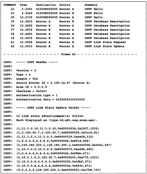
The packet trace in Figure 13.4 shows the beginning of an OSPF protocol exchange between two neighboring routers, routers A and B. After the second Hello from router A indicates bidirectional connectivity, the two routers start describing the current contents of their link-state databases by exchanging OSPF Database Description packets. When router B notices that some of its LSAs are out of date or that it is missing other LSAs, it requests the LSAs from router A in OSPF Link State Request packets. Router A then floods the requested LSAs to router B in OSPF Link State Update packets, just as if it were flooding newly received LSAs.
OSPF was designed with variable-length subnet masks in mind and always advertises the prefix mask instead of depending on Class A, B, and C network divisions. However, OSPF did require a bug fix when CIDR was deployed (see Section 3.7). A new version of the OSPF protocol has been designed as an IPv6 routing protocol (Section 3.7).
The Border Gateway Protocol (BGP) [208] is a Distance Vector EGP. BGP is the workhorse of the Internet; routing information is exchanged between the Internet’s ISPs using BGP. Each ISP expends a considerable amount of its people resources managing its BGP routing—deciding which other ISPs to peer with, maintaining the access lists of prefixes that can be received from and sent to each peer, and debugging the inevitable routing problems as they occur. Although BGP is the routing protocol that keeps the Internet running, it is used hardly at all in private TCP/IP networks. These networks typically run an IGP, such as OSPF; if they run BGP at all, they do so in only the single router that connects their network to the Internet. Figure 13.5 shows how BGP operates.
Figure 13.5. Operation of BGP. Received BGP updates are stored in the BGP router’s RIB-In. For each prefix, the best route from the RIB-In is installed in the routing table and then advertised to the router’s BGP peers.
The routers with which a BGP router X exchanges BGP information are called X’s BGP peers. A BGP router’s peers are configured by a network operator. To begin the exchange of BGP routing information with a peer, the BGP router sends a BGP Open message to the peer. If the peer also wishes to exchange BGP routing information, it responds with its own BGP Open message. At this point, the two routers exchange routing tables by transferring a collection of BGP Update messages. Each update message contains a list of prefixes and their BGP path attributes—attributes being the equivalent of other routing protocols’ metrics, which we discuss further later. After this initial exchange of routing tables, only changes are transmitted, again in BGP Updates. If changes are infrequent, the peers exchange BGP Keepalives to keep the BGP session established. Receipt of a BGP Notification message informs the router that the BGP session has been terminated, either because of an error or by intentional action by the network operator. When a session with a peer is terminated, all information learned from the peer is deleted from the router’s routing table.
BGP differs from a standard Distance Vector protocol in two significant ways. First, rather than continually resending their routing tables, after the first exchange of routing tables, two BGP routers send each other only changes. Transmission of routing updates must then be made reliable, which in BGP is accomplished by running over TCP. In standard Distance Vector protocols, such as RIP, if the best route disappears, the RIP router will know that it will be notified of all possible alternatives within the next 30 seconds. In contrast, since a BGP router’s peers transmit only changes, a BGP router must store any alternative routes that it receives in order to recover from failures of the primary route. BGP stores these alternative routes in a database called the RIB-In (Routing Information Base-Inbound). The size of the RIB-In can be many times the size of the router’s routing table.
Second, unlike standard Distance Vector algorithms, BGP always selects loop-free paths. To maintain loop-free routing a BGP router employs a simple mechanism: When advertising a prefix, the complete path to the prefix is included. Since the purpose of the BGP protocol is to exchange routing information between Autonomous Systems, this complete path consists of the sequence of ASs (called the AS path) that are traversed as data traffic is forwarded from the advertising router to the destination prefix. A router then avoids loops by never accepting an advertised prefix if the associated path already includes the router’s own AS number.
Let’s demonstrate this behavior by using the AS configuration of Figure 13.6 as an example. If the prefix 200.19.8.0/24 belongs to AS 3, it would be advertised in BGP updates from router A to router G (and from B to F and from B to I) with the AS path [AS 1, AS 2, AS 3]. If now the link between routers C and D fails, a standard Distance Vector protocol could form a loop between routers C–A–G–H–I–B–C, until counting to infinity removes the prefix from the routers’ routing tables. However, BGP prevents the loop because the advertisement for 200.19.8.0/24 from router I to B would carry the AS path [AS 5, AS 4, AS 1, AS 2, AS 3], which B would reject after seeing its own AS, AS 1, already in the path to the destination prefix.

Also unlike standard Distance Vector algorithms, BGP updates do not include a metric for each prefix. Since BGP routing updates can be thought of as providing a list of paths instead of a list of distances, BGP is sometimes referred to as a Path Vector protocol.
Encapsulation: BGP runs over TCP, using TCP port number 179. Running over TCP ensures the reliable, sequenced delivery of BGP routing messages between BGP peers. Although BGP information is carried within TCP’s reliable byte stream, BGP information is still packetized. Each BGP packet has a 19-byte header, with the maximum BGP packet size 4,096 bytes.
Path characteristics: As seen earlier, BGP ensures that BGP routers find loop-free paths. However, the exact form that these paths take is determined by the routing policies configured by the network administrators. Unlike the other routing protocols considered in this chapter, BGP has no metric that it is trying to minimize. Instead, when a BGP router receives a number of paths to any particular destination, it chooses the most preferable path, based on configured policies. A common policy is to choose the path consisting of the fewest number of ASs. Another common policy is to allow the network administrator to associate a weight with each AS. The weight is a positive integer, with ASs of smaller weight preferred. Each path is then assigned a weight equal to the sum of the weights of its constituent ASs, with the paths having the smallest weight inserted into the routing table.
Neighbor discovery and maintenance: A BGP router’s peers are configured instead of being learned dynamically. When a BGP session is established between two peers, they exchange BGP Open messages and Keepalives. During the exchange of Open messages, the peers negotiate a Hold Time. If Hold Time is nonzero, no more than Hold Time seconds can elapse between BGP messages (Keepalives or Updates) received from the peer, or the peer will be declared unreachable and the BGP session terminated.
Routing data distribution: As in any Distance Vector protocol, BGP routers exchange routing tables in their routing updates. Each BGP Update message a router sends has two parts (Figure 13.7). The first part lists prefixes that the BGP router has deleted from its routing table; BGP calls these withdrawn routes. Next comes a list of prefixes all having common BGP path attributes. BGP calls these prefixes Network Layer Reachability Information (NLRI); the path attributes include the AS path discussed earlier and other BGP path attributes discussed later. Unlike the other routing protocols in this chapter, BGP Update messages are always sent directly to a peer; they are never broadcast or multicast.
Response to changes: As in any Distance Vector protocol, changes to the routing table in one BGP router invoke a distributed recalculation, with the router sending the changed parts of its routing table in BGP Update messages, which in turn cause its peers to recalculate their routing tables and to send Update messages, and so on. However, advertising the AS path with each prefix prevents common Distance Vector convergence problems, such as counting to infinity (Section 13.1). To keep a prefix’s AS path up to date, a BGP router prepends its own AS number to the prefix’s existing AS path before transmitting the prefix in an Update message to a peer. In our example, if router G accepts and installs into its routing table the update for 200.19.8.0/24 received from A having AS path [AS 1, AS 2, AS 3], it transmits the prefix to H with the prepended AS path of [AS 4, AS 1, AS 2, AS 3].
Routing table calculation: The process of calculating routing table entries from the RIB-In is called the Decision Process. Based on configured policy information, a preferred path for each prefix is installed in the routing table. The Decision Process is invoked when the RIB-In changes—when new BGP updates are received, or a BGP session with a neighbor terminates, causing all data received from that neighbor to be deleted from the RIB-In. The Decision Process also must be invoked on policy changes, as these changes may well affect which of the RIB-In’s paths are preferred.
Robustness/reliability: Unlike the operation of the other protocols in this chapter, a BGP router does not refresh its routing information, instead sending updates only when changes occur. Since BGP runs over TCP, BGP Updates are delivered reliably, in order, and free from corruption. However, implementation or router hardware errors resulting in the corruption and/or deletion of parts of the BGP RIB-In are not rectified until BGP sessions are restarted—a manual process.
Aggregation: A network operator can configure a BGP router so that it aggregates routing information. Aggregating multiple routes into a single prefix poses a problem: What path should be advertised for the aggregate? For example, suppose that in Figure 13.6, AS 1 is handing out pieces of two CIDR address blocks, 192.9.0.0/18 and 200.16.64.0/18, to its customers ASs 2–5. Router B is then configured to aggregate the BGP information received from ASs 2–5 into these two CIDR blocks before sending BGP updates to router F. But if the relevant part of router B’s routing table is as pictured in Table 13.2, there is no accurate AS path that can be used for either block. To solve this problem, BGP introduces the concept of an AS set. Whereas an AS path (also called an AS sequence) indicates the exact sequence of ASs encountered on the way to the destination, an AS set indicates only the ASs that may be encountered somewhere along the path. AS sequences and AS sets can be concatenated within a BGP path attribute. Using brackets to indicate AS sequences and braces to indicate AS sets, router B would advertise 192.9.0.0/18 with an AS path attribute of [AS 1, AS 2]{AS 3} and 200.16.64.0/18 with an AS path of [AS 1]{AS 2, AS 3, AS 4, AS 5} in its BGP updates to F.
Policy controls: BGP provides more opportunity for policy-based controls than do the other routing protocols in this chapter, combining the routing filters commonly deployed in Distance Vector protocols with the additional information provided by the AS path. BGP routers usually can be configured to accept a given set of prefixes, but only if they originated ultimately from a given AS. Alternatively, BGP routers usually can be configured to accept a different set of prefixes, but only if the paths to the prefixes go through a particular provider. Sometimes these routing policies can even be configured automatically. ISPs maintain databases, such as the RIPE database [215], that describe which prefixes belong to which providers, together with other information on BGP peerings between ISPs. People have then written tools that convert these databases into automatically generated BGP router configuration files.
Security: The first 16 bytes of a BGP message are reserved for authentication purposes. MD5-based authentication algorithms have been designed for BGP, similar to those used for RIPv2 and OSPF (Section 11.7.1). However, for BGP, this kind of authentication alone cannot prevent simple denial of service attacks, such as inserting TCP Resets to break the BGP routers’ underlying TCP session. Preventing these attacks would require the deployment of additional security mechanisms at the IP and/or TCP level.
Figure 13.7 shows the beginning of a BGP session between the two routers 200.8.2.1 and 200.8.2.2. After exchanging Open messages and Keepalives, the two routers send each other a full set of routing updates, starting with the BGP Update message sent by 200.8.2.1. This update advertises eight prefixes, all having the AS path [AS 1367, AS 12], and a next hop of 200.8.2.1 (the advertising router itself). The setting of the Origin attribute to IGP in the update indicates that the eight prefixes belong to AS 12.

The other routing protocols in this chapter rely on an objective metric to converge eventually on loop-free paths. The fact that BGP does not have a true routing metric and instead allows routers to pick their routes based on configured policies can lead to problems—grossly inconsistent policies can lead to routing oscillations and/or unreachable destinations. For example, suppose in that Figure 13.6, router G has been configured to prefer sending traffic through AS 5 on its way to AS 1 and that similarly, router H has been configured to prefer using AS 4 as transit. G and H will initially find direct routes to the prefixes in AS 1, but after exchanging BGP Updates, they will prefer each other briefly, until they each realize that a loop is formed and go back to their direct routes. This process could then repeat indefinitely.
BGP has undergone a number of revisions since it was first published in 1989 [137]. Currently version 4, referred to as BGP-4, is deployed in the Internet. Previous versions, BGP-2 and BGP-3, were also deployed in the Internet; BGP-4 is the first BGP version capable of advertising CIDR prefixes.
BGP was also modified to create the OSI Inter-Domain Routing Protocol (IDRP). There are three main differences between IDRP and BGP. First, although IDRP was created to advertise OSI addresses, it can also advertise routes for other protocol suites at the same time (similar to Integrated IS-IS; see Section 13.5). Second, a reliable transport for routing updates was built directly into IDRP rather than relying on an external protocol such as TCP. Finally, IDRP implements another level of routing hierarchy by allowing the organization of ASs into clusters; similar support was introduced into BGP under the term BGP confederations. IDRP is considerably more complicated than BGP and has never seen any significant deployment.
The EGP used by IPv6 will undoubtedly be some form of BGP/IDRP. To date, the exact details of the resulting protocol are somewhat up in the air. The original intention of the IPv6 designers was to use IDRP, because it already supported the addressing flexibility to express IPv6 addresses. However, lately more effort has gone into developing multiprotocol extensions to BGP-4 [124] that can be used to carry IPv6 routing information.
BGP information must be propagated across ASs. For example, in Figure 13.6, when router C learns BGP routing information from the neighboring AS 2, this information must somehow be conveyed to routers A and B so that it can be readvertised to ASs 4 and 6, respectively. In its original design, BGP accomplished this propagation by establishing BGP peering sessions between the routers of AS 1: A, B, and C. These sessions between routers belonging to the same Autonomous System are called Internal BGP (IBGP) sessions; BGP sessions between routers belonging to different Autonomous Systems are called External BGP (EBGP) sessions. Since IBGP routing exchanges are not protected against looping by the AS path mechanism, within each Autonomous System, every BGP router had to peer directly with every other BGP router. This situation is called full-mesh IBGP.
Because IBGP routing is not protected by AS path, policy inconsistencies between IBGP peers are potentially more serious than between EBGP peers, possibly resulting in routing loops. These problems have been seen in some networks, with the default IBGP preferences specified in the BGP specification and implemented by the two most common BGP implementations (Cisco and GATED) known to be at odds.
Full-mesh IBGP can strain the capacity of a BGP router. The more peers (IBGP or EBGP) a BGP router has, the greater the number of transport connections and the larger the Routing Information Base. Ever since BGP was devised, people have been working on ways to avoid the full-mesh IBGP requirement. Several proposals have since emerged, with two of them, BGP route reflection and BGP confederations, seeing significant deployment in today’s Internet.
In both BGP route reflection and BGP confederations, the AS is divided into regions, or clusters. BGP routers internal to each region then need establish IBGP sessions only with routers in their own region, with routers on the region boundaries establishing IBGP sessions with routers in other regions. Figure 13.8 shows a division of AS 1 into three such regions, with each region containing three IBGP speakers.
In BGP route reflection [17], one router in each region is designated the Route Reflector (RR). Each other router in the region (collectively called the Route Reflector’s client peers) establishes a single IBGP session to the Route Reflector. When the Route Reflector receives an IBGP update from one of its client peers, the Route Reflector forwards (or reflects) the update to its other clients and also to its peers in other regions. In Figure 13.8, A1 would be designated the Route Reflector for the leftmost region; IBGP updates received from A2 would be reflected by A1 to router A and also sent to the Route Reflectors in the two other regions (routers B1 and C1). The various Route Reflectors (routers A1, B1, and C1 in our example) are connected together in a full IBGP mesh, and so, when properly configured, IBGP route reflection resists routing loops. IBGP route reflection also employs two mechanisms to prevent loops in the case of misconfiguration. To prevent loops within a region, the Route Reflector inserts its client’s BGP Identifier into the ORIGINATOR_ID attribute when reflecting the client’s routes. The Route Reflector then knows never to reflect these labeled routes back to the originating client. To prevent loops between regions, each region is assigned a cluster ID. When advertising IBGP updates to another region, the Route Reflector prepends its cluster ID to a new BGP path attribute called the CLUSTER_LIST, which in turn prevents intercluster loops, just as the BGP AS path prevents inter-AS loops.
In BGP confederations [248], the regions are called confederations. Within a single confederation, full-mesh IBGP is performed. To prevent interconfederation loops, each confederation is assigned a confederation ID. A BGP router then prevents loops by prepending its confederation’s ID to the AS path attribute when sending IBGP updates to other confederations. To keep the division into confederations from being visible outside the AS, confederation IDs are later stripped from the AS path attribute at the AS boundary.
BGP Route Servers [94] are another proposed alternative, similar in many respects to BGP route reflection. In this proposal, regions are called clusters. Each cluster is assigned a Route Server, to which all other IBGP speakers in the cluster (called the Route Server’s clients) establish IBGP sessions. An IBGP update received by a Route Server from a client is sent to the other clients in the cluster and to the Route Server’s IBGP neighbors in other clusters. To avoid looping within a cluster, each client inserts its BGP Identifier into an ADVERTISER path attribute in updates sent to the Route Server. To prevent intercluster loops, cluster IDs are accumulated within an RCID path attribute similar in function to BGP’s AS path.
One last alternative is to use the AS’s Interior Gateway Protocol to propagate BGP information across the AS. The BGP-OSPF interaction document (Section 11.6.1) shows how to use OSPF to propagate BGP routes for prefixes belonging to neighbor ASs—that is, prefixes whose BGP AS path is of length 1. To propagate BGP information for prefixes having longer AS paths, a special OSPF LSA, called the external-attribute-LSA (Section 7.6) was designed but has never been deployed in a production network.
Each Update message contains a collection of path attributes and a list of prefixes sharing the attributes. BGP attributes employ type-length-value (TLV) encoding. The current list of BGP attribute types is given in [153] and is reproduced in Table 13.3. Some BGP attributes, such as the AS path, must be present in every Update message—these are called mandatory attributes. Another category of attributes, the transitive attributes, are carried unaltered from one BGP speaker to the next.
Table 13.3. BGP Path Attributes
Type Code | BGP Attribute | Category |
|---|---|---|
1 | ORIGIN | Mandatory |
2 | AS_PATH | Mandatory |
3 | NEXT_HOP | Mandatory |
4 | MULTI_EXIT_DISC | |
5 | LOCAL_PREF | |
6 | ATOMIC_AGGREGATE | |
7 | AGGREGATOR | Transitive |
8 | COMMUNITY | Transitive |
9 | ORIGINATOR_ID | |
10 | CLUSTER_LIST | |
11 | DPA | Transitive |
12 | ADVERTISER | |
13 | RCID_PATH |
As described earlier, the AS_PATH attribute is used to prevent BGP routing loops and also allows BGP to support certain routing policy configurations. The ORIGIN attribute indicates whether the AS path is complete. If the ORIGIN is set to IGP, the AS path is complete; otherwise (ORIGIN set to INCOMPLETE or EGP) the AS path may be only a subset of the ASs encountered on the way to the destinations. Most BGP routers can be configured to make policy decisions based on the ORIGIN attribute, although the main use of this attribute was to mark those routes that were learned by the (now historical) EGP protocol during the EGP-to-BGP transition.
The NEXT_HOP attribute can be used by a BGP router to indicate that data should be forwarded to an IP router other than the BGP router itself. Sometimes called third-party routing information, a similar field was present in the EGP protocol’s routing updates, and there are similar concepts in other protocols, such as OSPF’s forwarding address. NEXT_HOP eliminates extra forwarding hops in some situations (see Section 11.6.1).
MULTI_EXIT_DISC, LOCAL_PREF, and DPA are all metrics of a sort. When two neighboring ASs are connected at multiple points, one AS can use MULTI_EXIT_DISC (multiple exit discriminator) to inform the other AS which is the better entry point; the entry with the lower MULTI_EXIT_DISC value should generally be favored. A BGP router uses LOCAL_PREF (local preference) to tell its IBGP neighbors whether it should be a preferred exit point from the AS; BGP routers advertising higher LOCAL_PREF values are usually chosen as exits. The DPA (destination preference attribute [40]) can be used by a router to bias the routing of its BGP neighbors. DPA has been proposed as a mechanism to encourage symmetric routing (that is, traffic going from A to B takes the same path as traffic from B to A) in the Internet, although DPA has not been widely deployed. All these three metrics are advisory. Any BGP router can be configured to ignore them in favor of other routing policies.
When it combines a collection of routes into a single aggregate, the BGP router advertises the aggregate route with an AGGREGATOR attribute containing the router’s AS number and IP address. This attribute is for information purposes only. Another attribute, ATOMIC_AGGREGATE, was intended to prevent certain advertised aggregates from being later deaggregated (that is, overridden by more specific prefixes) by a router’s BGP peers; however, both the specification and implementation of this attribute seem to be minimal.
The COMMUNITY attribute [39] is used to group a collection of prefixes so that they can be treated as a single unit by configured BGP policies. A few standard communities are specified, such as the NO_EXPORT community—prefixes tagged with NO_EXPORT will not be advertised out of their Autonomous System. Other communities can be established by each AS. For example, an ISP might want to create a separate community for each of its customers. Using communities in this way would allow a policy, such as “Advertise the prefixes of customers A, B, and C to this peer only,” to be configured without explicitly itemizing the prefixes that belong to A, B, and C. Although labeled as transitive, the COMMUNITY attribute is commonly stripped at AS boundaries. The COMMUNITY attribute is similar in function to OSPF’s external route tag (Section 3.2).
The remaining attributes implement loop prevention in the various alternatives to full-mesh IBGP. ORIGINATOR_ID and CLUSTER_LIST are used by BGP route reflection [17], and ADVERTISER and RCID_PATH are used by the BGP Route Server proposal [94].
The BGP routers at an Autonomous System’s boundary may have much larger routing tables than the routers interior to the AS. The question is, How do the routers internal to the AS get enough routing information to participate in loop-free forwarding? If the AS does not provide transit services (that is, all traffic entering or leaving the AS has either a local source or a local destination) the answer is easy: Just have the BGP routers import a default route into the IGP.
Transit ASs have two alternatives for getting routing information into their interior routers. First, they can leak enough BGP information into the IGP so that, combined with a default route, the interior routers can make good forwarding decisions (Section 13.7). This brings up the subject of IGP synchronization. If the interior routers are learning BGP information through the IGP, the BGP routers on the other side of the AS should not readvertise these routes to their EBGP peers until the appropriate IGP routes have been installed. This is the general principle that a route should not be advertised unless it is being used for forwarding. For example, in Figure 13.6, router A would not readvertise AS 3’s networks to router G until these routes appear in AS 1’s IGP routing.
Using these mechanisms, the default-free ASs at the core of the Internet would have to leak the whole Internet routing table into their IGPs, which they are usually loathe to do. Instead they typically run IBGP between all their routers—commonly called Universal IBGP. In these ASs, the IGP is relegated to the role of resolving BGP NEXT_HOP addresses. (Another alternative, which is to tunnel traffic between the BGP routers, would work, although it has not been deployed, to my knowledge.)
The size of the routing tables in the Internet’s core routers is always a concern. To keep the routing tables small and to encourage aggregation, some of the backbone providers refuse to accept BGP updates for prefixes longer than a certain length. To date, the current limit is 18 bits, although addresses assigned before the advent of CIDR (for example, Class C networks falling into 192/8) are usually excluded from this limit.
BGP routing within the Internet has shown considerable instability, with a number of unexpected and pathological behaviors uncovered by studies (such as [132]) of BGP traffic patterns. To reduce the amount of BGP routing oscillations, some BGP implementations perform route dampening [254], whereby a BGP router seeing a prefix that is flapping (that is, is withdrawn and then reappears) will wait an interval before readvertising the prefix; the more often the prefix flaps, the longer the router will wait before readvertising.
When configuring BGP routing policies or when debugging BGP routing problems, you often want to find the ISP (and the people contacts) associated with a particular AS number. For example, you may suddenly find that the routing table size in your routers has doubled, with all new routes originating from a particular AS number. The Internic keeps a list of AS number assignments [7], Contact information for a particular AS can also be obtained by using the command whois -h rs.internic.net “as as-number”. The ISP community has developed other tools to analyze BGP routing, such as ASExplorer [6]. This tool can display the routes that are currently flapping in the Internet’s BGP system, the nets that are currently being announced by any given AS, contact information for the AS, and so on.
The Inter-Gateway Routing Protocol (IGRP) [96] is Cisco Systems’ proprietary routing protocol. IGRP is a Distance Vector IGP and is deployed in many Internet sites that use Cisco routers. Cisco has also used IGRP to route other protocol stacks, such as OSI.
IGRP is very similar to RIP. The main difference between the two protocols is their choice of metrics. Instead of using hop count, an IGRP router advertises six separate pieces of information with each destination: (a) the static delay that packets will incur, (b) the amount of bandwidth provided by the path to the destination, (c) the current traffic load on the path, (d) the path’s error rate, (e) the path’s MTU, and (f) the number of router hops to the destination. If it sees a routing advertisement from one of its neighbors, an IGRP router combines the first four of these factors into a single composite metric that is inversely proportional to available bandwidth and proportional to both delay and error rate (for the exact equation, see [96]). If an IGRP router sees the same destination being advertised by multiple neighboring routers, it chooses the path going through the router that advertises the smallest composite metric. IGRP’s composite metric allows better path discrimination than RIP’s hop count. For example, RIP cannot discriminate between a 9,600-baud line and a T1 line, whereas IGRP’s composite metric can.
IGRP’s hop-count metric is used to terminate the counting-to-infinity behavior experienced by IGRP and most Distance Vector protocols. When the number of hops to a destination exceeds a configured value (set to 100 by default and not to exceed 255), the destination is considered unreachable.
IGRP is more aggressive than most routing protocols in trying to spread out traffic for a single destination over multiple links (also called load sharing). Not only can traffic be spread across equal-cost paths (as is done in the OSPF and IS-IS protocols) but also, with care, an IGRP router can be configured to load share over paths of relatively similar costs.
Type: IGRP is a Distance Vector IGP.
Encapsulation: IGRP runs directly over the Internet Protocol, as IP protocol 88.
Path characteristics: An IGRP router selects the path with the smallest composite metric. For example, if two paths are otherwise equivalent, the path with the smaller static delay is chosen. Or, if two paths differ only in their available bandwidth, the one having the higher available bandwidth is chosen.
Neighbor discovery and maintenance: IGRP has no neighbor discovery or maintenance procedures aside from the exchange of routing updates.
Routing data distribution: An IGRP router broadcasts its routing table to its neighbors every 90 seconds. For each destination, the IGRP router advertises six properties of the path that the router is currently using to that destination: the path’s static delay, provisioned bandwidth, current load, error rate, MTU, and hop count.
Response to changes: When its routing table changes, an IGRP router sends triggered updates rather than waiting for the next 90-second epoch. However, unlike RIP, each triggered update in IGRP advertises the full routing table.
Routing table calculation: When an update for a destination is received from a neighbor, the path’s properties are modified to take into account the delay, bandwidth, and error characteristics of the link to the neighbor. When an IGRP router receives updates for the same destination from two or more neighbors, the (modified) path having the smallest composite metric is installed into the routing table and is then broadcast in the router’s own IGRP updates.
Robustness/reliability: To ensure that routing updates are delivered, an IGRP router sends a complete set of routing updates (describing the entire routing table) every 90 seconds. If the receiving IGRP router goes 270 seconds without receiving an update for a given destination, the router deems the destination unreachable.
Aggregation: Like RIP, IGRP automatically aggregates routing information at the boundary of a subnetted network. In the updated version of IGRP for CIDR addressing, called EIGRP, an EIGRP router can be configured to aggregate routes into any CIDR prefix (similar to the address aggregation that may occur at OSPF area borders; see Section 6.1).
Policy controls: Routing policies are implemented by configuring routing filters, which tell the IGRP routers which routes they are allowed to receive and which routes they are allowed to advertise. However, Cisco recommends that route filtering be performed mostly at the edge of an IGRP routing domain. For example, if two sets of routers did not want to exchange complete routing information, they could be broken into two separate routing domains; one or more routers participating in both IGRP routing domains would control which routes were advertised from one domain to the other (see Section 13.7).
Security: IGRP has no provisions to protect its routing protocol exchanges and data from security attacks.
To improve on the basic Distance Vector convergence properties, IGRP employs some of the same stabilizing mechanisms that are used by RIP. These mechanisms are triggered updates, split horizon, and hold down (Section 13.1).
Unlike the other routing protocols in this chapter, which express a default route as the prefix 0.0.0.0/0, IGRP allows the network administrator to say, “The default path should follow the same path as packets to network X.” For example, network X could belong to your service provider. Hello, the original NSFNET’s routing protocol, had similar logic, with the default path following network 10, the ARPANET’s network number.
Also like RIP, IGRP is not a “classless” routing protocol, assuming instead that the TCP routing domain consists of Class A, B, and C networks, possibly divided into fixed-sized subnets. In order to support CIDR addressing and also to improve the convergence properties of IGRP, Cisco developed Enhanced IGRP (EIGRP) [43].
EIGRP not only is capable of advertising CIDR prefixes but also contains significant changes in protocol mechanism and has improved convergence properties. EIGRP is still a Distance Vector protocol, but by implementing the Distributed Update ALgorithm (DUAL) of [82], it maintains loop-free paths even while the network changes, avoiding counting to infinity. As with previous proposals for loop-free Distance Vector protocols, DUAL maintains loop-free paths by synchronizing the distributed routing calculations across routers. This synchronization significantly complicates the basic Distance Vector algorithm.
Hello messages are added to monitor the reachability of neighbors.
A reliable transport mechanism is added to ensure the reliable and sequenced delivery of EIGRP messages between neighboring routers.
Instead of just keeping the best route, alternate loop-free routes must also be stored by the EIGRP router. If the best route has a cost of X, the alternate routes are those that are advertised by neighboring routers as having a cost less than X. If the neighbor advertising the best route fails, one of the alternate routes is placed into the routing table.
If the neighbor advertising the best route fails and there are no alternate paths, the EIGRP router begins a new distributed calculation for a loop-free route to the destination by contacting its neighbors. A neighbor having a loop-free route responds with the route; otherwise the neighbor contacts its neighbors. In essence, requests for recalculation flood through the network until a new loop-free route is returned. During this recalculation, the destination remains unreachable, similar to a hold-down operation.
Integrated IS-IS is an adaptation of the standard OSI connectionless data routing protocol, IS-IS, to be used for IP routing. Integrated IS-IS is also sometimes called Dual IS-IS. The basic protocol mechanisms for Integrated IS-IS, including the data-link encapsulation, are defined in the IS-IS specification (ISO document 10589 [112]). The Internet’s RFC 1195 [30] then defines how IP routing data is carried by the protocol and the required calculations to produce an IP routing table from this data. The resulting protocol can perform routing for the IP and OSI protocol stacks simultaneously; hence the term integrated. (The creators of Integrated IS-IS coined the term Ships in the Night, or SIN for short, for the alternative of running separate routing protocols for each protocol stack.)
Integrated IS-IS is not widely deployed in the Internet but is run in a handful of large ISPs employing Cisco routers. Integrated IS-IS is a link-state IGP that resembles OSPF in many ways.
The OSI terminology used in IS-IS is a little difficult to follow for people who are familiar only with TCP/IP. Routers are called Intermediate Systems (ISs); hence the name IS-IS for the standard protocol spoken between ISs. The packets used by the routing protocol are called Protocol Data Units (PDUs).
The individual pieces of the IS-IS link-state database are called link-state PDUs (LSPs). LSPs are distributed throughout the IS-IS routing domain by a reliable flooding algorithm similar to OSPF’s. IS-IS again uses the Dijkstra algorithm to calculate the router’s routing table from the collected LSPs. However, by restricting the maximum path length to 1,024, IS-IS improves the performance of the standard Dijkstra.
Routing domains running Integrated IS-IS can be organized into a two-level hierarchy by splitting the routing domain into IS-IS areas.
Encapsulation: Integrated IS-IS runs directly over the data-link layer. For example, when run over Ethernet, IP and Integrated IS-IS use separate Ethernet type codes; when run over an ATM subnet, an encapsulation (such as LLC/SNAP [133]) that can distinguish IP traffic from IS-IS control traffic must be used.
Path characteristics: A value between 1 and 32 is configured for each network segment, called circuit by IS-IS. The cost of a path is then the sum of the path’s constituent circuit costs. IS-IS selects the least-cost path(s). Path cost cannot exceed 1,024, or the path is deemed unusable.
Neighbor discovery and maintenance: Neighboring ISs are discovered through the periodic transmission and reception of IS-IS Hello PDUs (IIH PDUs). Each IIH PDU specifies a Hold Time: the number of seconds that the neighbor should maintain reachability to the sending IS without receiving further IIH PDUs. The Hold timer is set so that even if some IIH PDUs are dropped, the neighbor connection remains active.
Routing data distribution: An IS describes its local environment, for example, its attached circuits and their costs, IP prefixes, and so on, in at least 1 and not more than 256 LSPs. These LSPs are then reliably flooded throughout the IS-IS domain. The format of LSPs is rather free-form and easily extendable, with each LSP containing a sequence of TLV (type-length-value) encoded data items. A special LSP, called the pseudonode LSP, lists all of the ISs attached to a particular circuit (the equivalent of OSPF’s network-LSA). The collection of LSPs generated by all IS-IS routers forms the link-state database.
Response to changes: Changes in the local environment of an IS cause it to update one of its LSPs, originate a new LSP, or purge an LSP from the IS-IS routing domain. Purging an LSP works as follows. Each LSP has a Lifetime field, the number of seconds remaining before the LSP is considered to be defunct. In order to purge an LSP from all ISs’ link-state databases, the IS sets the LSP’s Lifetime to 0 and refloods the LSP.
Routing table calculation: IS-IS performs a Dijkstra calculation on the collection of LSPs, producing the routing table. The Dijkstra algorithm is made more efficient by limiting the path cost to values less than 1,024.
Robustness/reliability: In case LSPs are damaged or mistakenly discarded by an IS, each IS reoriginates its own LSPs every 15 minutes, whether or not the contents have changed. IS-IS also protects against flooding loops by decrementing an LSP’s Lifetime by at least 1 at each flooding hop, and an LSP checksum field detects LSP corruption during flooding or when held in the link-state database of an IS. IS-IS also ensures that a link is bidirectional before using the link in the Dijkstra calculation.
Aggregation: In Integrated IS-IS, routing information can be aggregated at area boundaries before being advertised into the Level 2 subdomain.
Policy controls: As with OSPF, area boundaries can be configured to implement certain policies. Data traffic stays within a single area if at all possible; if not, paths internal to the IS-IS routing domain are preferred over those that exit and reenter the domain.
Security: The PDUs of Integrated IS-IS may be authenticated. Only trivial authentication, a clear password such as that used by the TELNET application, has been completely defined for the protocol.
Because an IS can originate only a relatively small number (namely, 256) of LSPs, ISs typically create large LSPs containing a mixture of data: interface costs, area information, external routing information, and so on. However, since IS-IS runs over the data-link layer and does not have access to the fragmentation services of the network layer, care must be taken so that the size of any LSP does not exceed the MTU of any segment within the IS-IS domain.
An IS describes a collection of LSPs, using Sequence Number PDUs. Partial Sequence Number PDUs are used to acknowledge receipt of LSPs during the IS-IS reliable-flooding algorithm. Immediately after an IS discovers a neighboring IS, the two ISs synchronize link-state databases. Synchronization is performed by each IS sending a full summary of its link state-database, using Complete Sequence Number PDUs (CSNPs). After receiving the full set of Complete Sequence Number PDUs from the neighbor, an IS floods to its neighbor the LSPs that the neighbor is missing.
To simplify flooding over LANs, IS-IS elects a Designated Intermediate System for each LAN, similar to OSPF’s Designated Router. However, unlike OSPF, IS-IS does not explicitly acknowledge LSPs flooded over the LAN. Instead flooding reliability is achieved by having the Designated Intermediate System multicast a complete set of Complete Sequence Number PDUs onto the LAN every 10 seconds; in essence, the Designated Router is continually performing the full database synchronization with the other ISs on the LAN.
IS-IS is a little more laissez faire about database synchronization than is OSPF. For example, unlike OSPF, IS-IS does not require database synchronization over a circuit before the circuit is made available for data traffic. Also, because LSPs are not explicitly acknowledged on LANs, synchronization problems are somewhat more difficult to detect in IS-IS, and the LSP purge operation is not absolutely reliable.
The area routing scheme in IS-IS is subtly different from OSPF’s area routing. IS-IS requires a single physically connected Level 2 subdomain, with areas (Level 1 subdomains) directly connected to it. Partitions of areas are automatically repaired by tunneling (Section 1.2.3) through the Level 2 subdomain. On the other hand, OSPF’s central subdomain, called the OSPF backbone area, is not required to be physically connected, and OSPF has no provision to repair area partitions (see Chapter 6). IS-IS forces strict hierarchical routing between areas: Inter-area data traffic originating in one area follows a default route to the Level 2 subdomain, where it is forwarded by Level 2 routing to the destination area. In comparison, OSPF allows data traffic to bypass the backbone area through configuration of OSPF virtual links (Section 6.1.2).
IS-IS needed no modification to support CIDR addressing. The IS-IS protocol was developed at the same time that OSPF was designed. OSPF considered, but did not use, IS-IS as a starting point; see Section 3.2 for more information.
We have now discussed all the unicast routing protocols in use in the Internet today; multicast routing protocols are discussed in Chapter 14, Multicast Routing Protocols. However, additional unicast routing protocols have been deployed in or designed for the Internet in the past. They are mentioned briefly in this section for completeness; also included are further references for the interested reader.
The Gateway-to-Gateway Protocol (GGP) [101] was one of the Internet’s first routing protocols, a Distance Vector IGP run by the ARPANET’s routers when the ARPANET was the core of the Internet. GGP had a couple of unusual features for a Distance Vector protocol. To keep track of the state of a neighbor, a GGP router periodically sent GGP echo messages, expecting GGP echo replies in response. When j out of n (typically two out of four) replies were received, the neighbor was declared operational; if k out of n (typically three out of four) echoes failed to provoke responses, the neighbor was declared down. This procedure allowed the routing protocol to reject links having excessive error rates [146]. GGP also called for explicit acknowledgment of routing updates, allowing a GGP router to send changes only to a neighbor instead of continually rebroadcasting the entire routing table. GGP shared packet formats with another protocol that was being developed at the same time: EGP.
The Exterior Gateway Protocol (EGP) [162], [219] was the first instance of the class of Internet protocols called EGPs. Until replaced by BGP, EGP was the protocol used everywhere in the Internet for exchanging routing information between Autonomous Systems. EGP was a Distance Vector protocol that its designers felt did not have good enough convergence properties to be run over an arbitrary topology of ASs. For this reason, while running EGP, the Internet was forced into organizing its ASs into a strictly hierarchical tree structure. Since the AS topology was supposed to have no loops, EGP’s routing metric could be ignored (a metric being something to compare two different paths but there being only a single possible path in strict tree), earning EGP the reputation of being a reachability protocol rather than a routing protocol. Experience with EGP was a driving force in the design of BGP, from the compactness of routing updates (indexed by metric and next hop) to the way network administrators configured EGP to accomplish rudimentary forms of policy-based routing ([206]).
The Hello Protocol [161] was a Distance Vector IGP. Hello was deployed within the original NSFNET network, which consisted of LSI-11 routers (Fuzzballs) interconnected by 56K links. Hello’s distinguishing feature was its choice of routing metric: measured delay. As a result, Hello calculated least-delay paths for data traffic. When the NSFNET transitioned to IBM RT routers and T1 links, the Hello Protocol was replaced by a routing protocol (called the NSFNET IGP [207]) based on an early version of the IS-IS protocol specification.
Inter-Domain Policy Routing (IDPR) [236] is a link-state EGP. Designed as a replacement for the Internet’s EGP protocol, IDPR competed against BGP for widescale deployment in the Internet and eventually lost. IDPR is capable of expressing very sophisticated routing policies. For example, using IDPR, an AS could specify that it only allows commercial traffic during the hours from midnight until 5A.M. IDPR also has superior security provisions, allowing digital signatures on routing information along the lines of [190]. IDPR is considerably more complicated than other Internet routing protocols, and its abandonment of the Internet’s hop-by-hop routing paradigm probably sealed its doom. In the Internet, every router makes an independent decision on how to forward a packet, after consulting the router’s routing table. In contrast, the firsthop IDPR router calculates the entire path of a datagram and then explicitly installs the path in all the IDPR routers on the way to the destination, a procedure sometimes called flow setup.
As we have shown in this chapter, TCP/IP has many routing protocols. As originally designed, routers within an AS were to run a common routing protocol (IGP) among themselves, whereas a different routing protocol (EGP) was used to exchange routing information with other ASs. But in practice, routing in the Internet is a little more chaotic than originally designed, and it is not at all unusual for a router to be running three or four different routing protocols simultaneously.
When a router runs multiple routing protocols, it must arbitrate among them, performing the following tests on each learned route.
When a route is learned from a routing protocol, should it be accepted and installed in the routing table, to be used when forwarding data traffic?
When two or more routing protocols learn routes to the same destination, and all are acceptable, which route should be preferred?
When should destinations learned by one routing protocol be readvertised by another? If readvertised, what costs and other advertised parameters should be used?
These three tests are by no means independent. Only when a route passes test 1, the route filter, will it be eligible to enter the preference contest in test 2. And only if the route wins the preference test and is installed in the forwarding table will it be eligible for possible readvertisement by other routing protocols in test 3: A router readvertising a route that it does not really use in forwarding may create routing loops or black holes.
Designing these tests is a difficult task. Route filters are essentially hop-by-hop policy statements and work fairly well with Distance Vector algorithms, such as RIP and BGP. In fact, automated tools exist to generate BGP routing filters from Internet routing policy databases, such as the RIPE database [215]. However, route filters in general cannot be used on routes learned by the shortest-path calculation of a link-state routing protocol such as OSPF.
Deciding which routing protocol’s route to prefer is made difficult because of the different, incomparable routing metrics employed by the various protocols. OSPF assigns a 16-bit cost to each link, with no bound on path cost (Section 11.3.1). RIP uses hop count, with a maximum hop count of 16 (Section 13.1). BGP, like its precursor, EGP, really has no metric, making all of its routing decisions based on user-defined policies (Section 13.3). Integrated IS-IS assigns a cost of 1 to 32 to each link, with path cost capped at 1,024 (Section 13.5). And the list goes on.
These differing metrics also make it difficult to readvertise routes from one protocol to another. Should you try to translate the metric from one protocol into another or simply require the network administrator to configure the advertised costs? Either way, some information is lost when readvertising, which may lead to routing loops in some circumstances. This information loss during readvertisement is the reason why IBGP is used to transport BGP routing information across ASs rather than just importing the BGP information into the IGP at one side of the AS and the readvertising back into BGP at the other (although you can make an IGP carry full BGP information in some cases; see Sections 7.6 and 11.6.1). There are other issues besides differing metrics that make readvertisement difficult. For example, not all routing protocols can even express the same set of destinations—RIPv1, still in common use today, cannot express general CIDR prefixes but is instead limited to the traditional Class A, B, and C networks with fixed-sized subnets (see Section 1.2.2).
There are very few documents describing the interaction of multiple routing protocols. RFC 1812, Requirements for IP Version 4 Routers [12], has a few sections explaining general principles for arbitrating between multiple protocols and readvertising information from one protocol to another. Although at one point it looked as though the IETF was going to attempt to write documents defining the interaction between every pair of Internet routing protocols, the only document written to date is the one describing OSPF-BGP interaction (see Section 11.6.1).
Nonetheless all router vendors have been forced to design interactions between the various routing protocols they support, and by now, all vendors support a common core functionality. They all allow you to specify which destinations you are willing to accept from a given routing protocol, and, depending on protocol, you can filter on additional parameters. For example, using RIP, you can usually say that you will accept a route but only if it is received from a particular RIP neighbor. When using BGP, you can specify that the route have a given AS path or that it originated from a particular AS, and so on. To arbitrate among multiple protocols wishing to write the same routing table entry, they usually allow you to associate a preference value with each accepted route. And the vendor usually allows you to specify the exact list of networks to readvertise into a routing protocol, together with costs and other protocol-specific advertised attributes, such as the ability to modify advertised AS paths in BGP. To be sure, this leaves a lot of the responsibility for making things work with the network administrator who creates all this configuration, but such is the state of the art.
Let us use the GATED program [83] as an example. Suppose that our GATED box is talking BGP to neighboring AS 174, from which we are willing to accept the networks 18/8,192.1/16, and 199.18.93/24 but no others. Suppose that our GATED box is also talking RIP to router 10.1.4.200, from which we are willing to accept only 199.18.93/24 and 200.2.67/24. Furthermore, if we receive 199.18.93/24 from both BGP and RIP, we want the RIP route to win. Finally, we want the RIP routes, but not the BGP routes, imported into OSPF as external Type 2 routes of cost 1. This leads to the configuration file depicted in Figure 13.9.
The book Routing in Communications Networks by Steenstrup [237] provides a good description of routing algorithms used in packet-switching networks, such as the Internet. The book also covers routing in circuit-switched networks; high-speed networks, such as optical networks; and mobile networks, such as cellular and packet-radio networks.
For information on how the Internet’s BGP routing is configured and managed, see Internet Routing Architectures by Halabi [89].