
Appendix C. Graphical tool support
You’ve seen quite a bit of XML configuration throughout the example implementations in this book. Open source products often lack graphical tool support for implementing functionality, but Mule and ServiceMix do provide graphical tool support, each with its own Eclipse-based implementation. In this appendix, we provide a short introduction to both these tools.
Graphical tool support with Mule IDE 2.0
The first step is to install Mule IDE 2.0 in your Eclipse environment. If you haven’t already installed Eclipse 3.3.x, do so now. A good installation guide is available on the MuleSource website (http://www.mulesource.org/display/MULEIDE/Mule+IDE+2.0). Note that you have to deselect several parts of the EMF and GMF updates.
When you’ve installed all updates, including the Mule IDE 2.0 update, you’re ready to begin modeling Mule configurations with Mule IDE 2.0. You can start a new Mule IDE 2.0 project by choosing File > New to start the New Project wizard, shown in figure C.1.
Figure C.1. The New Project wizard in Eclipse, showing the Mule Project wizard that’s provided with the Mule IDE 2.0 Eclipse plug-in

When you click the Next button in the New Project wizard, you can add a default Mule distribution. Click the Add button, and select the location of your Mule 2.0.2 distribution directory. When you’ve finished the New Project wizard, the libraries of the selected default Mule distribution are automatically added to your project’s classpath. In addition, a conf directory is created automatically to host your Mule configuration files.
Click the conf directory and choose New > Other. Then, select Mule Configuration under the Mule directory, and a new Mule configuration is created. Eclipse automatically opens the Mule configuration canvas and palette, as shown in figure C.2.
Figure C.2. The Mule IDE configuration canvas and palette. The palette includes components and inbound and outbound routers, which are the fundamental elements of a Mule configuration.

The Mule configuration canvas and palette include familiar elements such as a component and an inbound and an outbound router. You can easily switch between the graphical view and the source code view of the Mule configuration by using the tabs at the bottom of the canvas.
Now, let’s build a simple Mule service to show the look and feel of the Mule IDE. Follow these steps to design a hello world example:
1. Select Seda Service from the Services tab of the Mule IDE palette, click the Mule IDE canvas, and enter the name HelloWorldService. This translates to a normal Mule service definition, as in all of this book’s Mule examples.
2. Select Java Component from the Components tab, and then click the component area of the Mule service you just created. A Java component is added to the service definition.
Enter esb.appendixc.HelloComponent in the Class property of the Eclipse properties view; this Java class returns a hello String with the input parameter name.
3. Switch to the Overview tab of the Mule IDE canvas to enable the JMS namespace. In the Namespace dialog box, select the JMS namespace.
4. To create a JMS ActiveMQ connector in the Overview tab, go to the Connectors window area and click Add. Choose the ActiveMQ connector at the top, and name it jmsConnector. You’ve now added an ActiveMQ connector definition to your Mule configuration.
5. Switch back to the Services tab. You can now select a JMS inbound endpoint from the palette’s Inbound tab. Click the JMS inbound endpoint, and then click the inbound area of the HelloWorldService in the canvas. In the Properties view of the JMS inbound endpoint, configure a JMS queue name, such as hello.in.
6. Complete the Outbound area of the Mule service. Add a pass-through router to the Outbound area from the Outbound palette, and then add a JMS outbound endpoint to this pass-through router.
You should now see a canvas similar to figure C.3.
Figure C.3. Mule IDE canvas showing the hello world example you just created

Now, switch to the Source tab of the Mule IDE to look at the Mule configuration XML file. The XML configuration is similar to the configurations in this book’s examples.
At the time of writing, the Mule IDE 2.0 is in its early stages, but you can see how easy it is to design a Mule configuration instead of typing XML yourself. The Mule IDE also provides support for deploying the Mule configuration on a Mule container. You can find more information on the Mule IDE website. But note that it’s a work in progress—not everything will work as expected just yet.
Graphical tool support with the Enterprise Integration Designer
Graphical tool support for ServiceMix is part of the Eclipse SOA Tools Platform Project (Eclipse STP), in the Enterprise Integration Designer (EID) subproject. The EID plug-in is donated by Bull, the company that started the Cimero plug-in project to provide a visual tool to design JBI service assemblies for Apache ServiceMix and PEtALS. The current version of the EID plug-in adds generator support for Apache Camel distributions. For more information about the EID plug-in, see http://www.eclipse.org/stp/eid/index.php.
To download the EID plug-in, you can use the Eclipse software-update tool at the Eclipse STP update website: http://download.eclipse.org/stp/updates/ganymede. Choose to install the STP Enterprise Integration Designer Feature, and complete the installation wizard. Then, you can create a new Eclipse project and add an EID diagram by choosing New > Other. The resulting New dialog box looks similar to figure C.4.
Figure C.4. The New wizard in Eclipse shows you how to create a new integration patterns diagram.
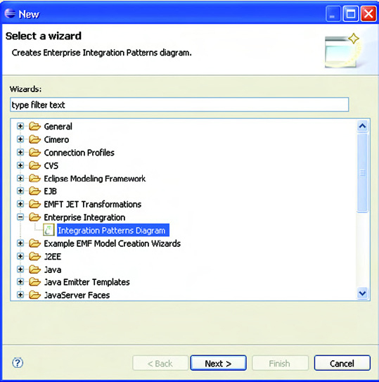
Select Integration Patterns Diagram, and then choose ServiceMix (from the three options Camel, PEtALS, and ServiceMix) as the target ESB implementation and click the Next button. On the last screen of the New wizard, choose the filename of the design diagram to be created, and click Finish. A canvas and a palette appear, as shown in figure C.5; you can use them to create a JBI service assembly for ServiceMix and PEtALS and a distribution for Apache Camel.
Figure C.5. The design canvas and palette of the Enterprise Integration Diagram plug-in

As you can see in figure C.5, you can use various integration functions of ServiceMix service engines and binding components to design an integration solution. Not all ServiceMix components are currently supported—for example, the Apache ODE service engine.
To demonstrate how to use the EID canvas and palette, let’s work through a simple example. Follow these steps:
1. Click the JMS binding component in the palette, and then click the canvas. The JMS binding component appears on the canvas; you can configure it in the properties view.
In the properties view, fill in the component name that will be used as the service unit name. In the Exclusive Properties – Consumer Property area, you can set many more properties. Be sure to complete at least the Endpoint, targetService, targetEndpoint, destinationName, Service – Value, and Exclusive Properties, and the connectionFactory properties.
2. To implement some content-based routing logic, click Content-based-router in the palette, and then click the canvas. Using the palette’s Connection element, you can connect the JMS consumer with the content-based router.
3. To configure the content-based router, you need to fill in quite a few properties. Enter the Component Name property, as you did for the JMS consumer. In the Namespace-context property, set an optional namespace to be used in the routing rules. Complete the Content-based-router properties, such as Endpoint, Service – Value, and Namespace.
You can define multiple routing rules using XPath expressions. For every routing rule, you must define an exchange target and a routing rule, just as you did in chapter 5 in the routing section. Define two routing rules for this example; just fill-in an XPath expression.
4. Add two JMS providers, which can be connected to the content-based router. As you did for the JMS consumer, you have to enter several properties.
The result of these steps should be similar to figure C.6.
Figure C.6. The result of the routing example you implemented in the EID canvas

You should now have three JMS binding components and one content-based router service engine. Now that you’ve designed the routing example, you can generate the JBI package by right-clicking the canvas and selecting Generate JBI package. When you refresh the Eclipse project, a folder is generated with the service assembly and the four service units. There is also an Ant build file that you can use to build the service assembly and deploy it to a ServiceMix container.
Note that the jbi.xml file in the service assembly is blank and doesn’t include the service assembly and service unit configuration. But this example gives you a first look at the functionality of the EID plug-in.