
We’re rich as son-of-a-bitch stew but look how homely we are, just as plain-folksy as Grandpappy back in 1836. We know about champagne and caviar but we talk hog and hominy. | ||
| --Edna Ferber | ||
This chapter is intended for programmers who are either new to OpenGL and learning it on a Windows platform or experienced with OpenGL on other platforms and learning the Windows-specific requirements for getting an OpenGL program up and running under Windows. This chapter covers the basics of getting a window ready to accept OpenGL calls. This involves getting a device context for the rendering window, selecting a pixel format, creating a rendering context for OpenGL to operate on, and, finally, cleaning up after all this preparation and creation. In this chapter we will cover just the interface layer between Windows and OpenGL—what you need to know about it and how you go about manipulating it.
Although it’s great that Windows finally has a real 3D API, the irritants that are part of GDI (graphics device interface) programming have to be endured. If you’re new to Windows programming, GDI refers to the Windows native 2D graphics API. For those of us who’ve been making a living at Windows programming, GDI is a necessary evil. Much like any other graphics API, GDI has its own quirks and eccentricities, and for most Windows programmers GDI’s quirks soon become part of the background noise of programming under Windows.
Fortunately most of the GDI quirkiness is gone from Windows OpenGL programming. In fact, getting GDI to work in an OpenGL window isn’t that easy! However, for most OpenGL implementations, there’s a platform-specific interface that requires twiddling before you can fire up OpenGL, and Windows is no exception.
Six basic steps are required to use OpenGL calls in a Windows program:
Getting a device context for the rendering location
Selecting and setting a pixel format for the device context
Creating a rendering context associated with the device context
Drawing using OpenGL commands
Releasing the rendering context
Releasing the device context
Those are the steps. However, even a Windows programmer won’t be able to make much sense of them, since OpenGL programming requires functions that are entirely new to Windows, starting with Windows NT 3.5 and as an additional subsystem on Windows 95. Let’s examine a bit of the terminology involved with setting up Windows to use OpenGL calls.
We’ve already mentioned GDI, Windows’ original 2D graphics interface. GDI is capable of drawing to the screen, to memory, to printers, or to any other device that provides a GDI interface layer and that can process GDI calls. This makes it simple to give your program the ability to print out a diagram that’s on the screen, since the drawing command essentially remains unchanged. GDI accomplishes this by a rendering “handle” to the currently selected device. This handle is called the device context, or DC. All GDI calls pass through a DC, and the DC does the correct thing. You can create a DC for the screen, do your rendering, switch to a printer DC, and render using the same commands again; what you saw on the screen will show up on the printer.
A rendering context, or RC, is the OpenGL equivalent of the GDI DC. An RC is the portal through which OpenGL calls are rendered to the device. The device context is, in part, GDI’s repository of state variables (the current color of the current pen, for example); the rendering context plays a similar function for OpenGL’s state variables. You can think of both of them simply as a data structure that keeps the state of the current settings and routes calls to the appropriate device. That’s pretty much how they are going to be treated in this book. Creating a DC and an RC before you start making your OpenGL calls is simply part of the ritual that you have to execute before you can use OpenGL functions. In this chapter we’ll examine what you need to know about DCs, RCs, and pixel formats and then describe the library function I’ve created that takes care of all this stuff for you.
Pixel formats are perhaps the only interesting part of the Windows OpenGL interface, and that’s because you can modify the pixel format to suit your needs. Modifying the pixel format is one of the areas that you can preselect in your program to optimize your OpenGL program, with no other changes to your OpenGL code. It’s also one of the least-discussed areas of Windows OpenGL programming, since it’s an entirely new part of the Windows API, created just for OpenGL. If you’re just interested in getting OpenGL up and running without getting into minute details of how the rendering device can be set up, you can skip the next section. The OpenGL initialization functions of the library will take care of setting all this up for you. However, if you’re interested in optimizing your program to get the maximum rendering speed out of it, you should spend some time studying the next section.
Pixel formats are the translation layer between OpenGL calls (such as an OpenGL call to draw a pixel with an RGB triad value of [128,120,135]) and the rendering operation that Windows performs (the pixel might be drawn with a translated RGB value of [128,128,128]). The pixel format that you’ve selected describes such things as how colors are displayed, the depth of field resolution, and what additional capabilities are supported by the rendering context you’ve created. The Windows OpenGL API has four functions that handle the pixel format. These are shown in Table 2.1. We’ll describe each of the functions and how it’s used.
Table 2.1. Functions for Manipulating the OpenGL Pixel Format
Pixel Format Function | Description |
|---|---|
| Obtains a device context’s pixel format that’s the closest match to a pixel format template you’ve provided. |
| Sets a device context’s current pixel format to the pixel format index specified. |
| Returns the pixel format index of a device context’s current pixel format. |
| Given a device context and a pixel format index, fills a |
The capabilities of an OpenGL window depend on the pixel format selected for the OpenGL rendering window. The properties of this format include
Single or double buffering
RGBA or color indexing
Drawing to a window or bitmap
Support of GDI or OpenGL calls
Color depth (depth = number of bits)
z-axis depth
Stencil buffer
Visibility masks
In Windows these values are set for each OpenGL window, using a data structure called the PIXELFORMATDESCRIPTOR. The pixel format has to be selected before the OpenGL rendering context is created. Once the pixel format is set for a rendering context, it cannot be changed.
The exact values of the PIXELFORMATDESCRIPTOR that are supported depend on the implementation of OpenGL that is running, the current video mode Windows is running in, and the video hardware you currently have installed. Generally you can be sure that you have at least the “generic” Windows implementation of OpenGL. This is a software-only version of OpenGL that’s provided by Microsoft, and it’s an important consideration if you intend your OpenGL programs to be distributed widely. You can be fairly sure that the generic implementation will be the slowest. If your computer has a video board that supports OpenGL, you’re getting some assurance that your OpenGL programs will run faster. However, even if a board has OpenGL hardware, there is no rule that the manufacturer has to provide a device driver to completely reroute calls to the hardware. Some manufacturers may implement only a limited set of OpenGL calls, leaving the generic driver to perform the rest. Such an implementation is called a Mini Client Driver. So the only way to be sure of the capabilities of your target system is to run tests and see what is present.
The following structure can be found in the Windows include file WINGDI.H
typedef struct tagPIXELFORMATDESCRIPTOR
{
    WORD  nSize;
    WORD  nVersion;
    DWORD dwFlags;
    BYTE  iPixelType;
    BYTE  cColorBits;
    BYTE  cRedBits;
    BYTE  cRedShift;
    BYTE  cGreenBits;
    BYTE  cGreenShift;
    BYTE  cBlueBits;
    BYTE  cBlueShift;
    BYTE  cAlphaBits;
    BYTE  cAlphaShift;
    BYTE  cAccumBits;
    BYTE  cAccumRedBits;
    BYTE  cAccumGreenBits;
    BYTE  cAccumBlueBits;
    BYTE  cAccumAlphaBits;
    BYTE  cDepthBits;
    BYTE  cStencilBits;
    BYTE  cAuxBuffers;
    BYTE  iLayerType;
    BYTE  bReserved;
    DWORD dwLayerMask;
    DWORD dwVisibleMask;
    DWORD dwDamageMask;
} PIXELFORMATDESCRIPTOR,
*PPIXELFORMATDESCRIPTOR,
FAR *LPPIXELFORMATDESCRIPTOR;
Table 2.2 is a breakdown of each element found in the PIXELFORMATDESCRIPTOR structure. You can consider this breakdown as a way of setting up the properties of the canvas that you are going to paint on with your OpenGL program, so you should have a good grasp of what those capabilities are.
Table 2.2. Elements in the PIXELFORMATDESCRIPTOR Structure
The generic implementation (up to OpenGL 1.1 on Windows NT and Windows 95) supports 24 pixel formats. Installed hardware may change or add additional capabilities. Each format is referred to by number (from 1 to n), but the ordering can change, depending on various factors, so don’t rely on the numbers to remain the same.
The pixel formats are grouped according to their properties. The primary property is the color depth, which ranges from 4 bits per pixel, through 8, 16, 24, and 32 bits per pixel. Eight formats are defined for the color depth specified by the display driver. These are referred to as the native formats. The remaining nonnative formats are divided among the other color depth values. These formats are grouped according to pixel type (RGBA or color index), single versus double buffered, and the depth of the depth buffer. Note that you can have a double buffer only if the format specified is a window, not a bitmap. Any additional formats that might be provided by OpenGL hardware are called device formats.
Now that we’ve examined what goes into the pixel format structure, let’s use it to examine pixel formats. The Windows function that fills a pixel format structure is DescribePixelFormat(). The following code fragment illustrates how it’s used:
// create a device context from the current window
CClientDC mydc(this);

// get a pixel format descriptor variable
PIXELFORMATDESCRIPTOR pfd;
int MaxNumberPixelFormats;

// if it succeeds, it returns the total number of formats
MaxNumberPixelFormats =
 DescribePixelFormat(
       dc.m_hDC,          // pass in a DC
       1,                 // select the first pixel format
       sizeof(pdf),       // size of struct to fill
       &pfd);             // ptr to struct

if ( 0 == MaxNumberPixelFormats )
       {
       // Something went wrong....
       // print out a message to the debug window
       TRACE("DescribePixelFormat Failed with "
              "%d
",GetLastError()) ;
       }
The class CClientDC creates a device context. This is Windows’ way of describing the selected window’s identity and properties. The function DescribePixelFormat() is called with the argument of 1 to describe the first pixel format. If this routine succeeds, it returns the total number of pixel formats on the system. If it fails, it returns a value of 0. A successful call fills in the PIXELFORMATDESCRIPTOR structure, which can then be examined.
Figure 2.1 shows the tool I’ve provided for displaying the pixel formats available on your PC. The source code can be found on the CD under Chapter 2/Pixel Format Enumeration Program. To use the program, you can either type in the name of the executable image, PIXELFMT.EXE, from a command prompt, or you can launch the program from the file manager. Once the program comes up (assuming that you don’t get a message stating that OpenGL is not on your system!), you’ll see a dialog box that is the main display of the pixel-format enumeration program.

You can press the Next Format or the Previous Format button and watch as the program runs up and down the listing of the pixel formats found on your system. You can use this program to explore the formats available on your system. Take a note of the formats, and then change your video settings and run the program again. You’ll see the formats change in accordance with what’s currently running on your system. For example, if you’re running in video graphics array (VGA) mode, you’ll never see a color depth greater than 256 colors, even if your video hardware is capable of it. And, as I’ll get into in the next section, the program can also be used to try various pixel-format template values that can then be passed to the OpenGL interface layer to see what it then returns to you as its “best match.”
Generally when you start out, you’ll have a pretty good idea of what properties you’ll want in an OpenGL program. You’ll know right away whether you want to render to a window or a bitmap and whether you want OpenGL support. If you’re going to be displaying some animation or some other rapidly changing scene, you’ll want a double-buffered window. If you’re going to be using a lot of colors or OpenGL’s lighting effects or you need nondefault colors, you’ll want an RGBA window and probably a color depth of at least 16 bits.
Once you’ve selected the main attributes for your window, you need to ask the system for such a window. This is where the next function comes in. ChoosePixelFormat() takes a const pointer to a partially filled-out pixel format structure—one that you’ve filled out with your desired pixel format attributes—and the function matches it against the available pixel formats, selecting one for you. The pixel format structure you passed in is filled out with the selected format attributes, and the function returns the index value of the selected format. It’s up to you to check to make sure that the selected format is acceptable and to retry with different values if the selection is not acceptable.
In the PIXELFMT program you may have noticed that you’re able to edit the values in the dialog box. This feature allows you to use the ChoosePixelFmt button to take the entered-in values and call ChoosePixelFormat() and then see what the returned values are. Note that not all of the entries have an effect on the chosen pixel format. The further you get away from the primary properties, the less effect the values will have on the chosen pixel format. Basically, color depth, z-buffer depth, and the flags have the major impact on the returned pixel format.
Finally, when you’ve found an acceptable pixel format, you call the next of the pixel format functions, SetPixelFormat(). This function takes a DC and a pixel format index and selects that format for the window associated with the DC. The entire process of filling out a desired pixel format descriptor, calling ChoosePixelFormat() to get a match, and then calling SetPixelFormat() to select the format for the device context can be illustrated as follows:
CClientDC mydc(this);
int SelectedPixelFormat;
BOOL retVal;

// Now create a pfd and fill it with what we'd like
PIXELFORMATDESCRIPTOR pfd =
      {
      sizeof(PIXELFORMATDESCRIPTOR),// size of this pfd
      1,                      // version number
      PFD_DRAW_TO_WINDOW  |   // support window
        PFD_SUPPORT_OPENGL |  // & OpenGL
        PFD_DOUBLEBUFFER,     // & double buffering
      PFD_TYPE_RGBA,          // RGBA type
      24,               // 24-bit color depth
      0, 0, 0, 0, 0, 0, // color bits ignored
      0,                // no alpha buffer
      0,                // shift bit ignored
      0,                // no accumulation buffer
      0, 0, 0, 0,       // accum bits ignored
      16,               // 16-bit z-buffer
      0,                // no stencil buffer
      0,                // no auxiliary buffer
      PFD_MAIN_PLANE,   // main layer
      0,                // reserved
      0, 0, 0           // no layer, visible, or damage masks
      };

// get the device context's best-available-match
// pixel format
SelectedPixelFormat =
      ChoosePixelFormat(mydc.m_hdc, &pfd);

ASSERT( 0 != SelectedPixelFormat );

// make that the device context's current pixel format
retVal = SetPixelFormat(mydc.m_hdc,
                  SelectedPixelFormat, &pfd);

// make sure it worked
ASSERT( TRUE == retVal );
That’s it for examining, choosing, and selecting a pixel format. One last function in the Windows OpenGL API deals with pixel formats: the GetPixelFormat() function, which is the matching function of SetPixelFormat(). As you can imagine, it returns the selected pixel format index, given a DC. The following code fragment illustrates how it works:
CClientDC mydc(this);
int SelectedPixelFormat;

// get the current pixel format for this DC
SelectedPixelFormat = GetPixelFormat(mydc.m_hdc);

// Make sure the call worked
ASSERT( 0 != SelectedPixelFormat );
Of course, this all seems like something best handled by a library routine and then best forgotten, and that’s exactly how pixel formats are going to be handled in the later chapters. If you examine the COpenGLView class that’s discussed in chapter 7, you’ll find that suggesting, verifying, and selecting a pixel format are all part of the creation routines of the view class. In fact, you don’t have to worry at all about the pixel format if you don’t want to, as it’s handled as part of the creation of the rendering context required for an OpenGL program running under Windows. When you create an OpenGL window, the rendering context is created along with the pixel format, and each is held inside the class structure. Some optional creation parameters let you have some control over what type of pixel format gets created, but in most cases you’ll probably be happy with the defaults.
Every OpenGL command is linked to a rendering context. A rendering context is what links OpenGL calls to a Windows window. Every thread of execution must have its own rendering context in order to be able to draw to the window.
If you’re a Windows programmer, you are familiar with the concept of a device context. In order to draw to a device using Windows’ native graphics interface, GDI, you first need to get or create a device context, or DC. When you execute a GDI command, you must first have a DC selected. The DC contains information about the device that GDI uses to render its commands with, as well as the current GDI settings for that DC, such as the current brush, pen color, and so on. An OpenGL rendering context, or RC, plays a similar role. If you fail to select an RC, your OpenGL calls will fail, and nothing will get drawn. A DC is also used when creating an RC. This connects GDI with OpenGL, since in the generic implementation it’s really GDI calls that are getting executed. Note that you don’t need the exact same DC each time; you just need a DC that matches the one that was used to create the RC initially. For example, you couldn’t mix an RC created with a screen DC and then reactivate it with a DC created for a printer. Finally, remember that a thread can have only one current RC (but many noncurrent RCs) and that an RC can be current only to one thread (but other threads can have that RC, as long as it’s not current).
Windows’ implementation of OpenGL has a number of routines that are used for managing rendering contexts. These are part of the “Windows GL,” or “wgl” (pronounced “wiggle”) functions. You’ll need to use these in order to have Windows set up a connection between a rendering device and OpenGL calls. Table 2.3 describes all of the context-rendering management functions found in Windows.
Table 2.3. Windows’ Context-Rendering Management Functions
Functions | Description |
|---|---|
| Creates a new OpenGL rendering context, suitable for drawing on the device referenced by the DC provided. The RC has the same pixel format as the DC. An application should set the DC’s pixel format before creating a rendering context. |
| Makes the specified RC the calling thread’s current RC. OpenGL calls made by the thread are then rendered on the device identified by the DC. If the RC specified is NULL, the function deselects the calling thread’s current RC and releases the DC used by the RC. In this case the DC is ignored. |
| Deletes the RC specified. It’s an error to delete an RC that is another thread’s current RC. However, if an RC is the calling thread’s current RC, the function makes the rendering context not current before deleting it. |
| If the calling thread has a current RC, the function returns a handle to that RC. Otherwise, NULL is returned. |
| If the calling thread has a current RC, the function returns a handle to the DC associated with that RC by means of |
The important wgl calls are wglCreateContext(), wglMakeCurrent(), and wglDeleteContext(). As you might expect, they are used to create, select, and delete RCs. Two additional functions deal with RCs: wglGetCurrentContext() and wglGetCurrentDC(). These functions are used to fetch the current thread’s RC and the RC’s associated DC.
The usual sequence is to get a DC, use it to create an RC, make the RC current, make your OpenGL calls, deselect the RC, delete it, and then release the DC. A legacy of 16-bit Windows was trying to run on a machine that (initially) only had 640K of memory to work with. Hence resources were very tight, and DCs in particular not only ate up memory but also were very easy to create and then forget about. This led to the practice of using a DC only when a message was passed to your program that told it that it needed to repaint its window, usually in response to a WM_PAINT message, which Windows sends when your program needs to redisplay itself. You’d simply wrapper your painting calls with a get DC/release DC pair. And you’d never hold on to a DC for the lifetime of your program, since the user might be running other applications, and they would need DCs to paint with.
However, with the 32-bit version of Windows, these problems can be dealt with in a less draconian manner. Windows now has a less restrictive architecture than was found in the old 16-bit days, and if a program creates and holds on to a DC, it’s no longer the mistake it once was. In fact, if you’re interested in high-performance computing, creating and releasing a DC is a time-consuming process, one best done sparingly.

That said, I’ll show you the two methods of creating an RC from a DC: the resource-penurious approach still habitually performed by old Windows programmers and the more streamlined approach, which favors execution speed at the expense of holding on to a DC for the lifetime of the OpenGL program. If you’re new to Windows programming, three messages passed to a program concern us here: WM_CREATE, WM_PAINT, and WM_DESTROY. These messages are passed to a program when it is being created, needs to repaint its display area, and is about to be terminated, respectively.
First, let’s examine the resource-penurious approach, illustrated in Figure 2.2. This approach can be done in two ways. One is to create an RC once and hold onto it; the other is to create the RC in response to each WM_PAINT message. I’ll discuss only the first way, since old Windows programmers using OpenGL are now on a 32-bit platform and so, ideally, won’t take resource conservation to the extreme. When a program receives a WM_CREATE message, you get a DC, set up your pixel format, create the RC by using wglCreateContext(), and then release the DC. When you receive a WM_PAINT, you’d get a DC, make the RC you’ve already created current by means of wglMakeCurrent(), perform your OpenGL calls, deselect the RC by using wglMakeCurrent() with null parameters, and then release the DC. Finally, when a WM_DESTROY message is delivered, you can delete the RC with wglDeleteContext().

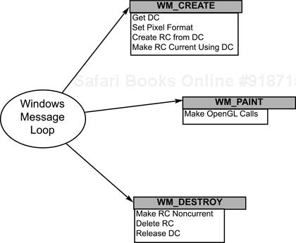
The optimized approach, illustrated in Figure 2.3, is to get a DC, set the pixel format, create the RC, and make the RC current, all when a WM_CREATE is received. This way, when the WM_PAINT calls are received—and there will usually be many of them—you need to perform only your OpenGL calls, since your RC is already created and selected. Finally, when the program is terminating, you deselect the RC, delete the RC, and release the DC. By the way, note the terminology: You delete the RCs, but you release the DCs. The 16-bit Windows had only a fixed number of DCs, so they were returned to Windows for reuse, as opposed to being created from scratch.


There’s not a whole lot to say about fonts under OpenGL. You’ll recall that OpenGL was designed to be a platform-independent, low-level, 3D graphics API. Therefore higher-level things, such as fonts, are left to the operating system to provide to OpenGL, either as bitmapped images or as a sequence of drawing primitives. This brings us to the two functions for converting fonts from Windows’ GDI format into an OpenGL-usable format.
First, however, we need a bit of background on how fonts are used natively in Windows. Normally a font is selected into the current GDI device context, and then the appropriate text-rendering functions are called, which render in the selected font. Things work the same way for OpenGL. A font is selected for the DC that’s associated with the current OpenGL RC, and then wgl functions are called that render one or more of the font glyphs into either 2D bitmaps or display lists of 3D primitives. Once the glyphs are in this format, you can treat them as any other OpenGL primitive.
The first function is wglUseFontBitmaps(). This function takes a DC and the desired glyphs and generates the bitmaps for the glyphs. You then use an OpenGL function with a text string to output the text in the form of bitmaps.
The second function is wglUseFontOutlines(); through the same procedure as the previous function, this function generates a series of 3D lines or polygons. The limitation with this function is that the font selected must be a TrueType font. These functions are too complex to discuss in a paragraph or two, so we’ll examine them in depth in chapter 7.
Double buffering is important in two cases. The first is when you don’t want the user to see the rendering being performed but would rather see the entire display updated at one time. The other time is when you need to perform animation or some other rapid updating of the OpenGL display. Since you’re reading this book, I’m going to assume that one of your major interests is getting OpenGL to run as fast as possible, so double buffering will be a brief but major part of the techniques we’ll use.
If you’ve selected a pixel format that supports double buffering, you’ve got an RC that directs OpenGL commands to the “back” buffer. You can think of this buffer as a memory bitmap that sits off screen. In the normal course of processing OpenGL commands, you’d issue your drawing commands and then tell OpenGL to flush any pending commands; this would force any cached rendering commands to be immediately displayed. For single-buffered pixel formats, your OpenGL commands would now be visible on the screen.
Double-buffered pixel formats, however, are rendered to the back buffer. What’s displayed on the screen is called the “front” buffer. The Windows API call to swap the front and back buffers is called SwapBuffers(). This call exchanges the front and back buffers of the specified DC. What this means to the user is that nothing is displayed on the screen until the buffers are swapped. Then the display appears to be “instantly” updated. If the particular video hardware you are using has enough video memory to support both buffers, this can be as fast as simply resetting the beginning offset of the currently displayed memory, which means that your display change could be as fast as the update frequency of your monitor, usually better than 75 Hz. Considering that if you can get a rate of 15 updates a second or better, your motion can be considered “flicker free,” which is pretty good.
You should be aware that double buffering isn’t really a method of speeding up your OpenGL program. Rather, it’s a method of making it appear to run more quickly, simply by letting the user see the individual frames “after” they have been drawn. In some cases—with good video hardware—double buffering will in fact make your programs run a bit faster, although the effect is swamped by the rendering time.
So if double buffering is so wonderful, why shouldn’t you use it all the time? There are only two cases in which you can’t use double buffering. One is when a double-buffered pixel format isn’t available; the other is when you want to use GDI calls in your OpenGL window. GDI and double buffering don’t mix; however, you can simulate your own by rendering to a bitmap and BLTing the bitmap with the screen display. However, in most cases you probably can use double buffering, and most of the example programs in this book use it, so if you discover that you can’t, you’ll have to modify the programs to be single buffered.
As a final note, if you want to take maximum advantage of an advanced OpenGL feature, you should be aware of the PFD_SWAP_COPY and PFD_SWAP_EXCHANGE flags mentioned previously. If your program has only certain areas of the OpenGL window that need to be updated or if you want a compromise between the effects of single buffering and double buffering, these flags can give you the ability to judiciously render only those areas of the screen that need it. Refer to the next section and the glGetString() function.
We’ve covered most of the OpenGL calls that you’ll need to use when using OpenGL under Windows. However, a few advanced functions should be mentioned to complete our account.
The first function is wglShareLists(). This function enables two or more OpenGL rendering contexts to share the same display list address space and textures objects. Normally when an OpenGL RC is created, it has its own unique address space for display lists. However, if your OpenGL threads are cooperative, they might want to share some information. For example, only one thread would need to create a display list for the characters of a particular font common to both threads. You’d want to avoid the overhead of creating and storing the same information for both threads, and this function provides a way to do it. You can share display list space only with threads within the same process and threads that use the same OpenGL implementation. Thus you can’t have one pixel format using the generic driver and another using a driver-supplied format, for example. As long as both RCs are using the same pixel format, they can always share the same display list address space. This function is available only on OpenGL version 1.01 or later.
The next function, wglGetProcAddress(), is a hook into the bowels of the OpenGL implementation you’re running. Your particular implementation might support some extensions that aren’t in the OpenGL API, and this function provides the ability to get the address of that functionality. This is all dependent on the implementation you are running, but with the original generic version 1.0 of OpenGL two extensions were originally available. We’ll examine how to find out about and use these extensions in chapter 12. You’ll need to examine the documentation that accompanied your OpenGL implementation to determine what extensions are available and how to use them.
If your video hardware supports it you can use hardware layer planes (overlay and underlay planes) in your applications. Layer planes are typically used for special visual effects. The pixel format descriptor describes the characteristics of the main plane. At about the time when Windows NT 3.51 shipped, pixel formats were extended to support overlay and underlay planes. Layer planes can look much like the main planes’ pixel configurations, and in fact may have more capabilities than the main plane. For example, a layer plane might support stereo while the main plane does not. Layer planes always have a front-left color buffer and also can include front-right and back color buffers. Each layer plane has a specific RC to render into the layer buffers. Layer planes have a transparent pixel color or index that enables any underlying layer planes to show through. Layer planes are beyond the scope of this book, but you can find out more about them by looking up the LAYERPLANEDESCRIPTOR in the compiler documentation.
As with anything else, the difficult part in creating an OpenGL program is learning what has to be done and figuring out how to do it. Once you’ve done it, repeating the performance is a simple matter. This section examines how to modify a simple Windows API skeleton to draw a simple OpenGL primitive. Its objective is simply to teach you the necessary parts that have to be added to a Windows API program to enable OpenGL calls to work. If you’re new to Windows programming, you should have no problem following along with the aid of a good Windows introductory book. If you’ve already written Windows programs, you should have no problem, since very few new calls are needed to get OpenGL to work.
This is not going to be an exhaustive explanation of how to write OpenGL programs for Windows using the Windows API. I’m going to use straight C API for 32-bit Windows. This is the only time you’ll see a straight C program for the Windows API. The rest of the book’s examples will be either simple OpenGL programs using the auxiliary library (which contain no Windows calls) or using the Microsoft Foundation Classes (MFC) C++ API as a wrapper to the Windows API. My reasoning is that it’s generally easier to write Windows programs using C++ and MFC than it is to use straight C and the Windows API.
The first thing is to go through all the things that you’ll have to add to a simple C Windows program in order to get it to be OpenGL ready.
Include the OpenGL header files:
glgl.h,glglu.h, and possiblyglglaux.h.Link with the OpenGL libraries:
opengl32.lib,glu32.lib, and possiblyglaux.lib.Before the window is created, set the window style to include
WS_CLIPSIBLINGSandWS_CLIPCHILDRENto prevent OpenGL from trying to draw into any other windows. You do this in the call toCreateWindow(), when you process theWM_CREATEmessage. You’ll then need to set up a pixel format and get an RC associated with the DC. You’ll hold onto this RC for the life of the program.You need to set the size of the OpenGL window according to the size of the window. The
WM_SIZEmessage is sent before the window is painted the first time and whenever the user resizes the window.Whenever the
WM_PAINTmessage is received, you’ll need to associate the RC with the DC (if it’s not already) and to do your OpenGL calls. This is where most of your OpenGL calls will occur.When the program is shutting down, you’ll receive a
WM_DESTROYmessage, and you’ll need to free the RC and release the DC.
Listing 2.1 is a simple Windows program that uses OpenGL. You can also find this program on the CD under CH02Simple. All of the interesting things occur in the processing of the WM_CREATE, WM_SIZE, WM_PAINT, and WM_DESTROY messages. The OpenGL-related processing occurs only in these message processes.
Example 2.1. A Simple Windows OpenGL Program
/*
    A Simple OpenGL program using a C interface
    designed to be a quick introduction into the minimal
    settings needed to run OpenGL under Microsoft Windows.
    (Does not hold onto the DC/RC)

    Ron Fosner - Dec. 1996
*/

#include <windows.h>    // standard Windows headers
#include <GL/gl.h>      // OpenGL interface
#include <GL/glu.h>     // OpenGL Utility Library interface

LONG WINAPI WndProc( HWND, UINT, WPARAM, LPARAM );
void DrawOpenGLScene( void );
HGLRC SetUpOpenGL( HWND hWnd );

//////////////////////////////////////////////////////////
// WinMain - the main window entrypoint,
//////////////////////////////////////////////////////////

int WINAPI WinMain (HINSTANCE hInstance,
                    HINSTANCE hPrevInstance,
                    LPSTR lpszCmdLine, int nCmdShow)
{
    static char szAppName[] = "OpenGL";
    static char szTitle[]="A Simple C OpenGL program";
    WNDCLASS wc;   // windows class struct
    MSG      msg;  // message struct
    HWND     hWnd; // Main window handle.

    // Fill in window class structure with parameters that
    // describe the main window.

    wc.style        =
        CS_HREDRAW | CS_VREDRAW;// Class style(s).
    wc.lpfnWndProc =
        (WNDPROC)WndProc;     // Window Procedure
    wc.cbClsExtra    = 0;     // No per-class extra data.
    wc.cbWndExtra    = 0;     // No per-window extra data.
    wc.hInstance     =
        hInstance;            // Owner of this class
    wc.hIcon         = NULL;  // Icon name
    wc.hCursor       =
        LoadCursor(NULL, IDC_ARROW);// Cursor
    wc.hbrBackground =
        (HBRUSH)(COLOR_WINDOW+1);// Default color
    wc.lpszMenuName  = NULL;  // Menu from .RC
    wc.lpszClassName =
        szAppName;            // Name to register as
    // Register the window class
    RegisterClass( &wc );

    // Create a main window for this application instance.

    hWnd = CreateWindow(
                szAppName, // app name
                szTitle, // Text for window title bar
                WS_OVERLAPPEDWINDOW// Window style
                  // NEED THESE for OpenGL calls to work!
                 | WS_CLIPCHILDREN | WS_CLIPSIBLINGS,
                CW_USEDEFAULT, 0, CW_USEDEFAULT, 0,
                NULL,     // no parent window
                NULL,     // Use the window class menu.
                hInstance,// This instance owns this window
                NULL      // We don't use any extra data
        );

    // If window could not be created, return zero
    if ( !hWnd )
        {
        return(0);
        }

    // Make the window visible & update its client area
    ShowWindow( hWnd, nCmdShow );// Show the window
    UpdateWindow( hWnd );       // Sends WM_PAINT message

    // Enter the Windows message loop
    // Get and dispatch messages until WM_QUIT
    while (GetMessage(&msg, // message structure
               NULL,       // handle of window receiving
                           // the message
               0,          // lowest message id to examine
               0))         // highest message id to examine
        {
        TranslateMessage( &msg ); // Translates messages
        DispatchMessage( &msg );  // then dispatches
        }

    return( msg.wParam );
}
//////////////////////////////////////////////////////////
// WndProc processes messages to our program.
// It's called WndProc because Windows expects it
// to be called that!
//////////////////////////////////////////////////////////

LONG WINAPI WndProc( HWND hWnd, UINT msg,
                     WPARAM wParam, LPARAM lParam )
{
      HDC hDC;
      static HGLRC hRC; // Note this is STATIC!
      PAINTSTRUCT ps;
      GLdouble gldAspect;
      GLsizei glnWidth, glnHeight;

      switch (msg)
        {
        case WM_CREATE:
            // Select a pixel format and then
            // create a rendering context from it.
            hRC = SetUpOpenGL( hWnd );
            return 0;

        case WM_SIZE:
            // Redefine the viewing volume and viewport
            // when the window size changes.

            // Make the RC current since we're going to
            // make an OpenGL call here...
            hDC = GetDC (hWnd);
            wglMakeCurrent (hDC, hRC);

            // get the new size of the client window
            // note that we size according to the height,
            // not the smaller of the height or width.
            glnWidth = (GLsizei) LOWORD (lParam);
            glnHeight = (GLsizei) HIWORD (lParam);
            gldAspect =
                 (GLdouble)glnWidth/(GLdouble)glnHeight;

            // set up a projection matrix to fill the
            // client window
            glMatrixMode( GL_PROJECTION );
            glLoadIdentity(); // Clear the projection matrix
            // a perspective-view matrix...
            gluPerspective(
                30.0,   // Field-of-view angle
                gldAspect, // Aspect ratio of view volume
                1.0,    // Distance to near clipping plane
                10.0 ); // Distance to far clipping plane

            glViewport( 0, 0, glnWidth, glnHeight );
            // deselect RC & Release DC
            wglMakeCurrent( NULL, NULL );
            ReleaseDC( hWnd, hDC );
            return 0;

        case WM_PAINT:
            // Draw the scene.

            // Get a DC, then make the RC current and
            // associated with this DC

            hDC = BeginPaint( hWnd, &ps );
            wglMakeCurrent( hDC, hRC );

            DrawOpenGLScene(); // draw our OpenGL scene

            // we're done with the RC, so
            // deselect it
            // (note: This technique is not recommended!)
            wglMakeCurrent( NULL, NULL );

            EndPaint( hWnd, &ps );
            return 0;

        case WM_DESTROY:
            // Clean up and terminate.
            wglDeleteContext( hRC );
            PostQuitMessage( 0 );
            return 0;
        }
    // This function handles any messages that we didn't.
    // (Which is most messages) It belongs to the OS.
    return DefWindowProc( hWnd, msg, wParam, lParam );
}

/////////////////////////////////////////////////////////
// SetUpOpenGL sets the pixel format and a rendering
// context then returns the RC
/////////////////////////////////////////////////////////

HGLRC SetUpOpenGL( HWND hWnd )
{
    static PIXELFORMATDESCRIPTOR pfd = {
        sizeof (PIXELFORMATDESCRIPTOR), // struct size
        1,                              // Version number
        PFD_DRAW_TO_WINDOW |    // Flags, draw to a window,
            PFD_SUPPORT_OPENGL, // use OpenGL
        PFD_TYPE_RGBA,      // RGBA pixel values
        24,                 // 24-bit color
        0, 0, 0,            // RGB bits & shift sizes.
        0, 0, 0,            // Don't care about them
        0, 0,               // No alpha buffer info
        0, 0, 0, 0, 0,      // No accumulation buffer
        16,                 // 16-bit depth buffer
        0,                  // No stencil buffer
        0,                  // No auxiliary buffers
        PFD_MAIN_PLANE,     // Layer type
        0,                  // Reserved (must be 0)
        0,                  // No layer mask
        0,                  // No visible mask
        0                   // No damage mask
    };

    int nMyPixelFormatID;
    HDC hDC;
    HGLRC hRC;

    hDC = GetDC( hWnd );
    nMyPixelFormatID = ChoosePixelFormat( hDC, &pfd );
    // catch errors here.
    // If nMyPixelFormat is zero, then there's
    // something wrong... most likely the window's
    // style bits are incorrect (in CreateWindow() )
    // or OpenGl isn't installed on this machine

    SetPixelFormat( hDC, nMyPixelFormatID, &pfd );

    hRC = wglCreateContext( hDC );
    ReleaseDC( hWnd, hDC );

    return hRC;
}

//////////////////////////////////////////////////////////
// DrawScene uses OpenGL commands to draw a triangle.
// This is where the OpenGL drawing commands live
//////////////////////////////////////////////////////////

void DrawOpenGLScene( )
{

    //
    // Enable depth testing and clear the color and depth
    // buffers.
    //
    glEnable( GL_DEPTH_TEST );
    glClear( GL_COLOR_BUFFER_BIT | GL_DEPTH_BUFFER_BIT );
    //
    // Define the modelview transformation.
    //
    glMatrixMode( GL_MODELVIEW );
    glLoadIdentity();

    // move the viewpoint out to where we can see everything
    glTranslatef( 0.0f, 0.0f, -5.0f );

    // Draw a large triangle out of three smaller triangles
    // sharing common vertex colors

    // Upper left triangle
    glBegin( GL_TRIANGLE );
        glColor3f( 0.0f, 0.0f, 0.0f ); // black center
        glVertex3f( 0.0f, 0.0f, 0.0f);
        glColor3f( 0.0f, 1.0f, 0.0f ); // left vertex green
        glVertex3f(-1.0f, -1.0f, 0.0f);
        glColor3f( 1.0f, 0.0f, 0.0f ); // upper vertex red
        glVertex3f( 0.0f, 1.0f, 0.0f);
    glEnd();

    // bottom triangle
    glBegin( GL_TRIANGLE );
        glColor3f( 0.0f, 0.0f, 0.0f ); // black center
        glVertex3f( 0.0f, 0.0f, 0.0f);
        glColor3f( 0.0f, 0.0f, 1.0f ); // right vertex blue
        glVertex3f( 1.0f, -1.0f, 0.0f);
        glColor3f( 0.0f, 1.0f, 0.0f ); // left vertex green
        glVertex3f(-1.0f, -1.0f, 0.0f);
    glEnd();

    // upper right triangle
    glBegin( GL_TRIANGLE );
        glColor3f( 0.0f, 0.0f, 0.0f ); // black center
        glVertex3f( 0.0f, 0.0f, 0.0f);
        glColor3f( 1.0f, 0.0f, 0.0f ); // upper vertex red
        glVertex3f( 0.0f, 1.0f, 0.0f);
        glColor3f( 0.0f, 0.0f, 1.0f ); // bottom right blue
        glVertex3f( 1.0f, -1.0f, 0.0f);
    glEnd();

    // Flush the drawing pipeline since it's single buffered
    glFlush ();
}For the real Windows programs that we’ll be examining, I’ve chosen to use Microsoft’s MFC class library as the platform. Quite a few PC compiler vendors have chosen to provide support for MFC, as well as MFC existing in some UNIX flavors, so it’s a fairly popular platform for Windows development. However, most of the important OpenGL information doesn’t depend on MFC at all but was covered in the simple C interface program listed previously, and the examples that use MFC can be easily edited to move the OpenGL parts to a simple C program.
I’ve chosen to use MFC because it’s popular, seems to be the emerging standard for writing Windows programs, and, when all is said and done, is a fairly easy interface to hook user interface processing to. The pixel-format enumerator program was written using MFC, and the UI took me about two hours to hook up to the pixel format code. So it’s also a reasonably good platform for program development. The only unfortunate part about using MFC is that the programs created by AppWizard (Microsoft’s program-template generation utility) are not small by any means. AppWizard has many options, most of which we’ll ignore, but even the minimal set of options still leaves us with many files generated.
If you’re new to C++ programming you may be confused by the syntax in some of the C++ examples later in this book. I use C++ here because it’s the most popular object-oriented language, and MFC in particular since MFC is the most popular and widely supported framework for writing C++ Windows programs. However, since many of the functions in the example C++ classes do similar things to the MFC classes, or to Windows or OpenGL functions, they sometimes have names that are similar; names may even be the same if they meet certain situations. To distinguish between local functions and external Windows or OpenGL functions, I always use the global scope resolution operator, ::, (e.g., a double colon), so that both the compiler and the programmer know exactly which function is being called. For example, the line
SetPixelFormat( 5 );
might be calling a local function in my class, or it might be calling a global Windows function of the same name. For clarity I always preface global functions with the global scope resolution operator. Thus, to make sure that I’m calling the global function, the above line of code should read:
::SetPixelFormat( 5 );
Even though the scope resolution operator doesn’t need to be used all the time, it’s a good habit to get into.
In order to reduce the volume of uninformative source code, only the modified functions of the AppWizard-generated programs will be displayed in the text; however, the entire set of files needed to edit and recompile any of the example programs can be found on the CD. In chapter 6, we’ll create the OpenGL MFC platform that we’ll base the rest of the examples on, building up functionality and capabilities.
That pretty much wraps it up for the Windows OpenGL API. You now have enough knowledge on the Windows OpenGL interface to be able to correctly set up a Windows program for OpenGL. In fact, you should also have some ideas as to what to look out for when setting up your program for maximum rendering speed—all before you write your first line of OpenGL code.
Programming OpenGL Windows programs requires a paradigm shift for experienced Windows programmers. You’re suddenly faced with unfamiliar function calls, multidimensional values, and a shifting base of basic capabilities. On the other hand, you now have the power to create animated, interactive, 3D graphics programs, knowing that a swarm of hardware manufacturers are currently creating optimized video boards that will make today’s OpenGL programs run twenty to fifty times faster! You should take this as a challenge to write the most efficient OpenGL code so that you can fit in as many frames per second of animation as you can, because in two or three years your “top-end” platform will be on the low end of PC platforms selling then. Now is the time to start writing 3D applications and to set your sights high, because not only are you writing programs to eke out all possible speed but the new accelerated graphics hardware that is starting to appear will also help speed up your application.