Project 7.19—Stepper Motor Control Projects—Simple Unipolar Motor Drive
This project is about using stepper motors in microcontroller-based systems. This is an introductory project where a stepper motor is driven from a microcontroller.
Before going into the details of the project, it is worthwhile to look at the theory and operation of stepper motors briefly.
Stepper motors are commonly used in printers, disk drives, position control systems, and many more systems where precision position control is required. Stepper motors come in a variety of sizes, shapes, strengths, and precision. There are two basic types of stepper motors: unipolar and bipolar.
Unipolar Stepper Motors
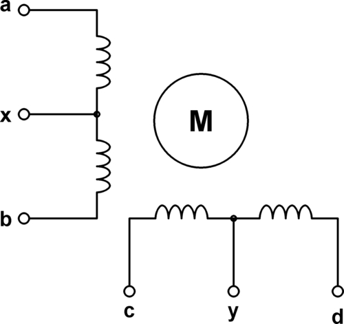
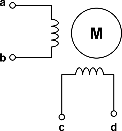
Unipolar stepper motors have two identical and independent coils with center taps, and having five, six, or eight wires (Figure 7.160).
Unipolar stepper motors can be driven in three modes: One-phase full-step sequencing, two-phase full-step sequencing and two-phase half-step sequencing.
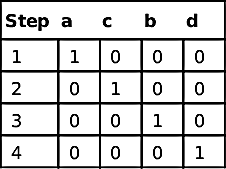
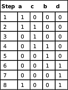
One-phase Full-step Sequencing
Table 7.20 shows the sequence of sending pulses to the motor. Each cycle consists of four pulses.
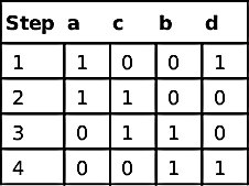
Two-phase Full-step Sequencing
Table 7.21 shows the sequence of sending pulses to the motor. The torque produced is higher in this mode of operation.
Two-phase Half-step Sequencing
Table 7.22 shows the sequence of sending pulses to the motor. This mode of operation gives more accurate control of the motor rotation, but it requires twice as many pulses for each cycle.
As we shall see later in the project, the motor can be connected to a microcontroller using power transistors or power MOSFET transistors.
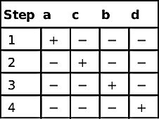
Bipolar Stepper Motors
Bipolar stepper motors have two identical and independent coils and four wires, as shown in Figure 7.161.
The control of bipolar stepper motors is slightly more complex. Table 7.23 shows the driving sequence. The “+” and “−” signs denote the polarity of the voltage that should be given to the motor legs. Bipolar stepper motors are usually driven using H-bridge circuits.
Project Description
In this project, a unipolar stepper motor is used and the motor is rotated for 100 turns before it is then stopped.
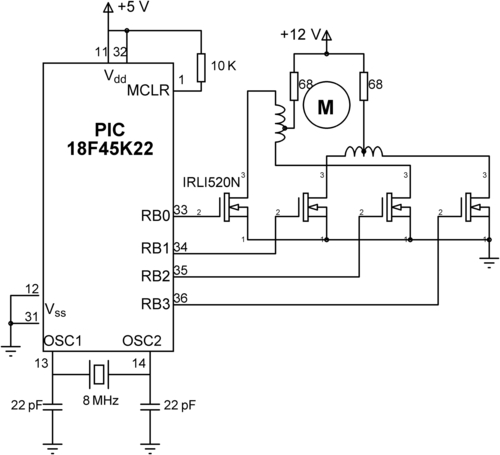
Project Hardware
The circuit diagram of the project is shown in Figure 7.162. In this project, an UAG2 type unipolar stepping motor is used. The motor is connected to RB0:RB3 pins of the microcontroller via IRLI520N-type power MOSFET transistors. UAG2 is a small stepper motor with an 18° stepping angle. Thus, a complete revolution requires 20 pulses. In this example, the motor rotates 100 turns (i.e. 2000 pulses are given), and then it stops. A 3-ms delay is inserted between each pulse to slow down the motor.
The pin connections of the UAG2 motor is as follows:
| Pin | Description |
| 1 | Start of first coil |
| 3 | Middle connection of first coil |
| 5 | End of first coil |
| 2 | Start of second coil |
| 4 | Middle connection of second coil |
| 6 | End of second coil |
Project PDL
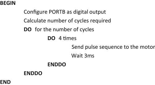
The project PDL is shown in Figure 7.163.
Project Program
mikroC Pro for PIC
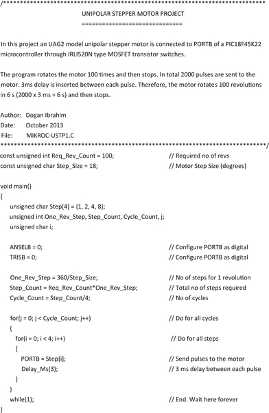
The mikroC Pro for the PIC program listing is given in Figure 7.164 (MIKROC-USTP1.C). The motor is operated in one-phase full-step sequencing mode. At the beginning of the program, the required number of revolutions and the moor step size are defined. Inside the main program array Step stores the sequence of pulses to be sent to the motor in each cycle. PORTB is configured as a digital output. Then, the cycle count is calculated and pulses are sent to the motor inside two for loops. The motor rotates 100 revolutions where 2000 pulses are sent to the motor. A 3-ms delay is inserted between each pulse. Therefore, the motor operates for 6 s. The speed of the motor can be calculated to be 1000 revolutions per minute (rpm).
..................Content has been hidden....................
You can't read the all page of ebook, please click here login for view all page.