
Software is complex, one of the most complex endeavors humankind has ever undertaken. When you first read the requirements document for a large-scale programming project
, you may feel overwhelmed. That’s expected; the task is overwhelming! For this reason, largescale programming projects typically begin with analysis.
The analysis phase
of a project consists of the time spent exploring the problem domain in order to understand the problem completely, clarify the requirements, and resolve any ambiguities between the client’s and developer’s domains. Without fully understanding the problem, you, as the architect or developer, have absolutely no chance of developing a maintainable design. For the case study chosen for this book, however, the domain should be familiar (if not, you may wish to pause here and partake in an analysis exercise). Therefore, we will skip a formal, separate analysis phase. That said, aspects of analysis can never be skipped entirely, and we will explore several analysis techniques during the construction of our design. This intentional coupling
of analysis and design emphasizes the interplay between these two activities to demonstrate that even for the simplest of problem domains, producing a good design requires some formal techniques for analyzing the problem.
One of the most important techniques we have as software designers
for addressing inherent problem complexity is hierarchical decomposition. Most people tend to decompose a problem in one of two ways: top down or bottom up. A top-down approach
starts by looking at the whole picture and subsequently subdividing the problem until reaching the bottom-most level. In software design, the absolute bottom-most level is individual function implementations. However, a top-down design might stop short of implementation and conclude by designing objects and their public interfaces. A bottom-up approach
would start at the individual function or object level and combine components repeatedly until eventually encompassing the entire design.
For our case study, both top-down and bottom-up approaches will be used at various stages of the design. I find it practical to begin decomposition in a top-down fashion until bulk modules and their interfaces are defined, and then actually design these modules from the bottom up. Before tackling the decomposition of our calculator, let’s first begin by examining the elements of a good decomposition.
2.1 The Elements of a Good Decomposition
What makes a decomposition good? Obviously, we could just randomly split functionality into different modules and group completely unconnected components. Using the calculator as an example, we could place arithmetic operators and the GUI in one module while placing trigonometric functions with the stack and error handling in another module. This is a decomposition, just not a very useful one.
In general, a good design will display attributes of modularity
, encapsulation
, cohesion
, and low coupling
. Many developers will have already seen many of the principles of a good decomposition in the context of object-oriented design
. After all, breaking code into objects is itself a decomposition process. Let’s first examine these principles in an abstract context. Subsequently, I’ll ground the discussion by applying these principles to pdCalc.
Modularity
, or breaking components into independently interacting parts (modules), is important for several reasons. First, it immediately allows one to partition a large, complex problem into multiple, smaller
, more tractable components. While trying to implement code for the entire calculator at once would be difficult, implementing an independently functioning stack is quite reasonable. Second, once components are split into distinct modules, unit tests can be defined that validate individual modules instead of requiring the entire program to be completed before testing commences. Third, for large projects, if modules with clear boundaries and interfaces are defined, the development effort can be divided between multiple programmers, preventing them from constantly interfering with each others’ progress by needing to modify the same source files.
The remaining principles of good design, encapsulation
, cohesion
, and low coupling
all describe characteristics that modules should possess. Basically, they prevent spaghetti code. Encapsulation, or information hiding, refers to the idea that once a module is defined, its internal implementation (data structures and algorithms) remains hidden from other modules. Correspondingly, a module should not make use of the private implementation of any other module. That is not to say that modules should not interact with each other. Rather, encapsulation insists that modules interact with each other only through clearly defined, and, preferably, limited interfaces. This distinct separation ensures that internal module implementation can be independently modified without concern for breaking external, dependent code, provided the interfaces remain fixed and the contracts guaranteed by the interfaces are met.
Cohesion
refers to the idea that the code inside a module should be self-consistent or, as the name implies, cohesive. That is, all of the code within a module should logically fit together. Returning to our example of a poor calculator design, a module mixing arithmetic code with user interface code would lack cohesion
. No logical ties bind the two concepts together (other than that they are both components of a calculator). While a small code, like our calculator, would not be completely impenetrable if it lacked cohesion
, in general, a large, noncohesive code base is very difficult to understand, maintain, and extend.
Poor cohesion can manifest in one of two ways: either code that should not be together
is crammed together or code that should be together is split apart. In the first instance, code functionality is almost impossible to decompose into mentally manageable abstractions because no clear boundaries exist between logical subcomponents. In the latter situation, reading or debugging unfamiliar code (especially for the first time) can be very frustrating because a typical execution path through the code jumps from file to file in a seemingly random fashion. Either manifestation is counterproductive, and I thus prefer cohesive code.
Finally, we’ll examine coupling. Coupling
represents the interconnectedness of components, be it functional coupling or data coupling. Functional coupling occurs when the logical flow of one module requires calling another module to complete its action. Conversely, data coupling is when data is shared between individual modules either via direct sharing (e.g., one or more modules point to some set of shared data) or via passing of data (e.g., one module returning a pointer to an internal data structure to another module). To argue for zero coupling is clearly absurd because this state would imply that no module could communicate in any way with any other module. However, in good design, we do strive for low coupling. How low should low be? The glib answer is as low as possible while still maintaining the ability to function as necessary. The reality is that minimizing coupling
without detrimentally complicating code is a skill acquired with experience. As with encapsulation
, low coupling is enabled by ensuring that modules communicate with each other only through cleanly defined, limited interfaces. Code that is highly coupled is difficult to maintain because small changes in one module’s design may lead to many unforeseen, cascading changes through seemingly unrelated modules. Note that whereas encapsulation
protects module A from internal implementation changes to module B, low coupling
protects
module A from changes to the interface of module B.
2.2 Selecting an Architecture
Although it is now tempting to follow the above guidelines and simply start decomposing our calculator into what seem like sensible constituent components, it’s best to first see if someone else has already solved our problem. Because similar problems tend to arise frequently in programming, software architects have created a catalog of templates for solving these problems; these archetypes are called patterns
. Patterns
typically come in multiple varieties. Two categories of patterns that will be examined in this book are design patterns [6] and architectural patterns.
Design patterns are conceptual templates used to solve similar problems that arise during software design; they are typically applied to local decisions. We will encounter design patterns repeatedly throughout this book during the detailed design of our calculator. Our first top level of decomposition, however, requires a pattern of global scope that will define the overarching design strategy, or, software architecture. Such patterns are naturally referred to as architectural patterns.
Architectural patterns are conceptually similar to design patterns; the two differ primarily in their domains of applicability. Whereas design patterns are typically applied to particular classes or sets of related classes, architectural patterns typically outline the design for an entire software system. Note that I refer to a software system rather than a program because architectural patterns can extend beyond simple program boundaries to include interfaces to hardware or the coupling of multiple independent programs. Two architectural patterns of particular interest for our case study are the multi-tiered architecture and the model-view-controller (MVC) architecture. We’ll examine each of these two patterns in the abstract before applying them to pdCalc. The successful application of an architectural pattern to our case study will represent the first level of decomposition for the calculator.
2.2.1 Multi-Tiered Architecture
In a multi-tiered, or n-tiered, architecture, components are arranged sequentially in tiers. Communication is bidirectional via adjacent tiers, but nonadjacent tiers are not permitted to communicate directly. An n-tiered architecture is depicted in Figure 2-1.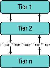
Figure 2-1
A multi-tiered architecture with arrows indicating communication
The most common form of the multi-tiered architecture
is the three-tiered architecture. The first tier is the presentation layer, which consists of all of the user interface code. The second tier is the logic layer, which captures the so-called “business logic
” of the application. The third tier is the data layer, which, as the name implies, encapsulates the data for the system. Very often, the three-tiered architecture is applied as an enterprise-level platform, where each tier could represent not only a different local process, but possibly a different process operating on a different machine. In such a system, the presentation layer would be the client interface, whether it be a traditional desktop application or a browser-based interface. The logic layer of the program could run on either the client or server side of the application or, possibly, on both. Finally, the data layer would be represented by a database that could be running locally or remotely. However, as you shall see with pdCalc, the three-tiered architecture can also be applied to a single desktop application.
Let’s examine how the three-tiered architecture obeys our general decomposition principles. First and foremost, at the highest level of decomposition, the architecture is modular. At least three modules, one for each tier, exist. However, the three-tiered architecture does not preclude multiple modules from existing at each tier
. If the system were large enough, each of the primary modules would warrant subdivision. Second, this architecture encourages encapsulation
, at least between tiers. While one could foolishly design a three-tiered architecture where adjacent tiers accessed private methods of neighboring tiers, such a design would be counterintuitive and very brittle. That said, in applications where the tiers coexist in the same process space, it is very easy to intertwine the layers, and care must be taken to ensure this situation does not arise. This separation is achieved by clearly delineating each layer via definitive interfaces. Third, the three-tiered architecture is cohesive. Each tier of the architecture has a distinct task, which is not commingled with the tasks of the other tiers. Finally, the three-tiered architecture truly shines as an example of limited coupling
. By separating each of the tiers via clearly defined interfaces, each tier can change independently of the others. This feature is particularly important for applications that must execute on multiple platforms (only the presentation layer changes platform to platform) or applications that undergo unforeseen replacement of a given tier during their lifetimes (e.g., the database must be changed due to a scalability problem).
2.2.2 Model-View-Controller (MVC) Architecture
In the Model-View-Controller architecture, components are decomposed into three distinct elements aptly named the model, the view, and the controller. The model abstracts the domain data, the view abstracts the user interface, and the controller manages the interaction between the model and the view. Often, the MVC pattern is applied locally to individual GUI widgets at the framework level where the design goal is to separate the data from the user interface in situations where multiple distinct views may be associated with the same data. For example, consider a scheduling application with the requirement that the application must be able to store dates and times for appointments, but the user may view these appointments in a calendar that can be viewed by day, week, or month. Applying MVC, the appointment data is abstracted by a model module (likely a class in an object-oriented framework
), and each calendar style is abstracted by a distinct view (likely three separate classes). A controller is introduced to handle user events
generated by the views and to manipulate the data in the model.
At first glance, MVC seems no different than the three-tiered architecture with the model replacing the data layer, the view replacing the presentation layer, and the controller replacing the business logic layer. The two architectural patterns are different, however, in their interaction pattern. In the three-tiered architecture, the communication between layers is rigidly linear. That is, the presentation and data layers talk only bidirectionally to the logic layer, never to each other. In MVC, the communication is triangular. While different MVC implementations differ in their exact communication patterns, a typical implementation is depicted in Figure 2-2. In this figure, the view can both generate events to be handled by the controller and get the data to be displayed directly from the model. The controller handles events from the view, but it can also directly manipulate either the model or the controller. Finally, the model can be acted upon directly by either the view or the controller, but it can also generate events
to be handled by the view. A typical such event would be a state change event that would cause the view to update its presentation
to the user.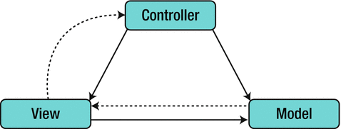
Figure 2-2
An MVC architecture with arrows indicating communication. Solid lines indicate direct communication. Dashed lines indicate indirect communication (e.g., via eventing) [30].
As we did with the three-tiered architecture, let’s now examine how MVC obeys the general decomposition principles. First, an MVC architecture will usually be broken into at least three modules: model, view, and controller. However, as with the three-tiered architecture, a larger system will admit more modules because each of the model, view, and controller will require subdivision. Second, this architecture also encourages encapsulation
. The model, view, and controller should only interact with each other through clearly defined interfaces, where events and event handling are defined as part of an interface. Third, the MVC architecture is cohesive. Each component has a distinct, well-defined task. Finally, we ask if the MVC architecture is loosely coupled. By inspection, this architectural pattern is more tightly coupled than the three-tiered architecture because the presentation layer and the data layer are permitted to have direct dependencies. In practice, these dependencies are often limited either through loosely coupled event handling or via polymorphism with abstract bases classes. Typically, however, this added coupling
does usually relegate the MVC pattern to applications in one memory space. This limitation directly contrasts with the flexibility of the three-tiered architecture
, which may span applications over multiple memory spaces.
2.2.3 Architectural Patterns Applied to the Calculator
Let’s now return to our case study and apply the two architectural patterns discussed above to pdCalc. Ultimately we’ll select one as the architecture for our application. As previously described, a three-tiered architecture consists of a presentation layer, a logic layer, and a data layer. For the calculator, these tiers are clearly identified as entering commands and viewing results (via either a graphical or command line user interface), the execution of the commands, and the stack, respectively. For the MVC architecture, we have the stack as the model, the user interface as the view, and the command dispatcher as the controller. Both calculator architectures are depicted in Figure 2-3. Note that in both the three-tiered and MVC architectures, the input aspects of the presentation layer or view are responsible only for accepting the commands, not interpreting or executing them. Enforcing this distinction alleviates a common problem developers create for themselves: the mixing of the presentation layer with the logic layer.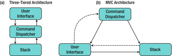
Figure 2-3
Calculator architecture options
2.2.4 Choosing the Calculator’s Architecture
From Figure 2-3, one quickly identifies that the two architectures partition the calculator into identical modules. In fact, at the architectural level, these two competing architectures differ only in their coupling. Therefore, in selecting between these two architectures, we only need to consider the design tradeoffs between their two communication patterns.
Obviously, the main difference between the three-tiered architecture and the MVC architecture is the communication pattern between the user interface (UI)
and the stack. In the three-tiered architecture, the UI and stack are only allowed to communicate indirectly through the command dispatcher. The biggest benefit of this separation is a decrease in coupling
in the system. The UI and the stack need to know nothing about the interface of the other. The disadvantage, of course, is that if the program requires significant direct UI and stack communication, the command dispatcher will be required to broker this communication, which decreases the cohesion
of the command dispatcher module. The MVC architecture has the exact opposite tradeoff. That is, at the expense of additional coupling, the UI can directly exchange messages with the stack, avoiding the awkwardness of the command dispatcher performing added functionality unrelated to its primary purpose. Therefore, the architecture decision reduces to examining whether or not the UI frequently needs a direct connection to the stack.
In an RPN calculator, the stack acts as the repository for both the input and output for the program. Frequently, the user will wish to see both the input and output exactly as it appears on the stack
. This situation favors the MVC architecture with its direct interaction between the view and the data. That is, the calculator’s view does not require the command dispatcher to translate the communication between the data and the user because no transformation of the data is required. Therefore, I selected the model-view-controller
as the architecture for pdCalc. The advantages of the MVC architecture over the three-tiered architecture are, admittedly, small for our case study. Had I instead chosen to use the three-tiered architecture, pdCalc still would have had a perfectly valid design.
2.3 Interfaces
Although it might be tempting to declare the first level of decomposition complete with the selection of the MVC architecture, we cannot yet declare victory. While we have defined our three highest level modules, we must also define their public interfaces. However, without utilizing some formal method for capturing all the data flows in our problem, we are very likely to miss key necessary elements of our interface. We therefore turn to an object-oriented analysis technique
, the use case.
A use case is an analysis technique that generates a description of a specific action a user has with a system. Essentially, a use case defines a workflow. Importantly, a use case does not specify an implementation. The customer should be consulted during use case generation, particularly in instances where a use case uncovers an ambiguity in the requirements. Details concerning use cases and use case diagrams can be found in Booch et al [4].
For the purpose of designing interfaces for pdCalc’s high-level modules, we will first define the use cases for an end user interacting with the calculator. Each use case should define a single workflow, and we should provide enough use cases to satisfy all of the technical requirements for the calculator. These use cases can then be studied to discover the minimal interactions required between the modules. These communication patterns will define the modules’ public interfaces. An added benefit of this use case analysis is that if our existing modules are insufficient to implement all of the workflows, we will have uncovered the need for additional modules in our top-level design.
2.3.1 Calculator Use Cases
Let’s create the use cases for our requirements. For consistency, use cases are created in the order in which they appear in the requirements.
2.3.1.1 Use Case: User Enters a Floating Point Number onto the Stack
- Scenario: The user enters a floating point number onto the stack. After entry, the user can see the number on the stack.
- Exception: The user enters an invalid floating point number. An error condition is displayed.
2.3.1.2 Use Case: User Undoes Last Operation
- Scenario: The user enters the command to undo the last operation. The system undoes the last operation and displays the previous stack.
- Exception: There is no command to undo. An error condition is displayed.
2.3.1.3 Use Case: User Redoes Last Operation
- Scenario: The user enters the command to redo the last operation. The system redoes the last operation and displays the new stack.
- Exception: There is no command to redo. An error condition is displayed.
2.3.1.4 Use Case: User Swaps Top Stack Elements
- Scenario: The user enters the command to swap the top two elements on the stack. The system swaps the top two elements on the stack and displays the new stack.
- Exception: The stack does not have at least two numbers. An error condition is displayed.
2.3.1.5 Use Case: User Drops the Top Stack Element
- Scenario: The user enters the command to drop the top element from the stack. The system drops the top element from the stack and displays the new stack.
- Exception: The stack is empty. An error condition is displayed.
2.3.1.6 Use Case: User Clears the Stack
- Scenario: The user enters the command to clear the stack. The system clears the stack and displays the empty stack.
- Exception: None. Let clear succeed even for an empty stack (by doing nothing).
2.3.1.7 Use Case: User Duplicates the Top Stack Element
- Scenario: The user enters the command to duplicate the top element on the stack. The system duplicates the top element on the stack and displays the new stack.
- Exception: The stack is empty. An error condition is displayed.
2.3.1.8 Use Case: User Negates the Top Stack Element
- Scenario: The user enters the command to negate the top element on the stack. The system negates the top element on the stack and displays the new stack.
- Exception: The stack is empty. An error condition is displayed.
2.3.1.9 Use Case: User Performs an Arithmetic Operation
- Scenario: The user enters the command to add, subtract, multiply, or divide. The system performs the operation and displays the new stack.
- Exception: The stack size is insufficient to support the operation. An error condition is displayed.
- Exception: Division by zero is detected. An error condition is displayed.
2.3.1.10 Use Case: User Performs a Trigonometric Operation
- Scenario: The user enters the command for sin, cos, tan, arcsin, arccos, or arctan. The system performs the operation and displays the new stack.
- Exception: The stack size is insufficient to support the operation. An error condition is displayed.
- Exception: The input for the operation is invalid (e.g., arctan(−50) produces an imaginary result). An error condition is displayed.
2.3.1.11 Use Case: User Performs y x
- Scenario: The user enters the command for y x . The system performs the operation and displays the new stack.
- Exception: The stack size is insufficient to support the operation. An error condition is displayed.
- Exception : The input for the operation is invalid (e.g., −10.5 produces an imaginary result). An error condition is displayed.
2.3.1.12 Use Case: User Performs ![$$ sqrt[x]{y} $$](http://images-20200215.ebookreading.net/6/5/5/9781484230572/9781484230572__practical-c-design__9781484230572__A454125_1_En_2_Chapter_IEq1.gif)
- Scenario: The user enters the command for
![$$ sqrt[x]{y} $$](http://images-20200215.ebookreading.net/6/5/5/9781484230572/9781484230572__practical-c-design__9781484230572__A454125_1_En_2_Chapter_IEq2.gif) . The system performs the operation and displays the new stack.
. The system performs the operation and displays the new stack. - Exception: The stack size is insufficient to support the operation. An error condition is displayed.
- Exception: The input for the operation is invalid (e.g.,
![$$ sqrt[4]{-1} $$](http://images-20200215.ebookreading.net/6/5/5/9781484230572/9781484230572__practical-c-design__9781484230572__A454125_1_En_2_Chapter_IEq3.gif) produces an imaginary result). An error condition is displayed.
produces an imaginary result). An error condition is displayed.
2.3.1.13 Use Case: User Loads a Plugin
- Scenario: The user places a plugin into the plugins directory. The system loads the plugin on startup, making the plugin functionality available.
- Exception: The plugin cannot be loaded. An error condition is displayed.
2.3.2 Analysis of Use Cases
We will now analyze the use cases for the purpose of developing C++ interfaces for pdCalc’s modules. Keep in mind that the C++ language
does not formally define a module concept. Therefore, think of an interface conceptually as the publicly facing function signatures to a collection of classes and functions grouped logically to define a module. For the sake of brevity, the std namespace prefix is omitted in the text.
Let’s examine the use cases in order. As the public interface
is developed, it will be entered into Table 2-2. The exception will be for the first use case, whose interface will be described in Table 2-1. By using a separate table for the first use case, we’ll be able to preserve the errors we’ll make on the first pass for comparison to our final product. By the end of this section, the entire public interface for all of the modules will have been developed and cataloged.
Table 2-1
Public Interfaces
Derived from the Analysis of the Use Case for Entering a Floating Point Number onto the Stack
Functions | Events | |
|---|---|---|
User Interface |
void displayError(const string&)
void stackChanged()
|
numberEntered(double) |
Command Dispatcher |
void numberEntered(double)
|
error(string)
|
Stack |
void push(double)
void getElements(n, vector<double>&)
|
stackChanged()
|
Table 2-2
Public Interfaces
for the Entire First Level Decomposition
Functions | Events | |
|---|---|---|
User Interface |
void postMessage(const string&)
void stackChanged()
|
commandEntered(string)
|
Command Dispatcher |
void commandEntered(const string&)
|
error(string)
|
Stack |
void push(double)
void getElements(n, vector<double>&)
double pop()
void swapTop()
|
stackChanged()
error(string)
|
We begin with the first use case: entering a floating point number. The implementation of the user interface
will take care of getting the number from the user into the calculator. Here, we are concerned with the interface required to get the number from the UI onto the stack.
Regardless of the path the number takes from the UI to the stack, we must eventually have a function call for pushing numbers onto the stack
. Therefore, the first part of our interface is simply a function on the stack module, push(), for pushing a double precision number onto the stack. We enter this function into Table 2-1. Note that the table contains the complete function signature, while the return type and argument types are omitted in the text.
Now, we must explore our options for getting the number from the user interface module to the stack module. From Figure 2-3b, we see that the UI has a direct link to the stack. Therefore, the simplest option would be to push the floating point number onto the stack directly from the UI using the push() function we just defined. Is this a good idea?
By definition, the command dispatcher module
, or the controller, exists to process commands the user enters. Should entering a number be treated differently than, for example, the addition command? Having the UI bypass the command dispatcher and directly enter a number onto the stack module violates the
principle of least surprise
(also referred to as the
principle of least astonishment
). Essentially, this principle states that when a designer is presented with multiple valid design options, the correct choice is the one that conforms to the user’s intuition. In the context of interface design, the user is another programmer or designer. Here, any programmer working on our system would expect all commands to be handled identically, so a good design will obey this principle.
To avoid violating the principle of least surprise, we must build an interface that routes a newly entered number from the UI through the command dispatcher
. We again refer to Figure 2-3b. Unfortunately, the UI does not have a direct connection to the command dispatcher, making direct communication impossible. It does, however, have an indirect pathway. Thus, our only option is for the UI to raise an event (you’ll study events in detail in Chapter 3). Specifically, the UI must raise an event indicating that a number has been entered, and the command dispatcher must be able to receive this event (eventually, via a function call in its public interface). Let’s add two more functions to Table 2-1, one for the numberEntered() event raised by the UI and one for the numberEntered() event handling function in the command dispatcher.
Once the number has been accepted, the UI must display the revised stack. This is accomplished by the stack signaling
that it has changed, and the view requesting n elements from the stack and displaying them to the user. We must use this pathway because the stack only has an indirect communication channel
to the UI. We add three more functions to Table 2-1: a stackChanged() event on the stack module, a stackChanged() event handler on the UI, and a getElements() function on the stack module (see the “Modern C++ Design Note” sidebar on move semantics
to see options for the getElements() function signature). Unlike the entering of the number itself, it is reasonable to have the UI directly call the stack’s function for getting elements in response to the
stackChanged() event
. This is, in fact, precisely how we want a view to interact with its data in the MVC pattern.
Of course, the aforementioned workflow assumes the user entered a valid number. For completeness, however, the use case also specifies that error checking must be performed on number entry. Therefore, the command dispatcher should actually check the validity of the number before pushing it onto the stack, and it should signal the user interface if an error has occurred. The UI should correspondingly be able to handle error events
. That’s two more functions for Table 2-1: an error() event on the command dispatcher
, and a function, displayError(), on the UI, for handling the error event. Note that we could have selected an alternative error handling design by leaving the UI to perform its own error checking and only raise a number entered event for valid numbers. However, for improved cohesion
, I prefer placing the “business logic” of error checking in the controller rather than in the interface.
Phew! That completes our analysis of the first use case. In case you got lost, remember that all of the functions and events just described are summarized in Table 2-1. Now just 12 more exciting use cases to go to complete our interface analysis! Don’t worry, the drudgery will end shortly. We will soon derive a design that can consolidate almost all of the use cases into a unified interface.
Before proceeding immediately to the next use case, let’s pause for a moment and discuss two decisions we just implicitly made about error handling. First, the user interface handles errors by catching events rather than by catching exceptions. Because the user interface cannot directly send messages to the command dispatcher, the UI can never wrap a call to the command dispatcher in a try block. This communication pattern immediately eliminates using C++ exceptions for inter-module error handling (note that it does not preclude using exceptions internally within a single module). In this case, since number entry errors are trapped in the command dispatcher
, we could have notified the UI directly using a callback. However, this convention is not sufficiently general, for it would break down for errors detected in the stack since the stack has no direct communication with the UI. Second, we have decided that all errors, regardless of cause, will be handled by passing a string to the UI describing the error rather than making a class hierarchy of error types. This decision is justified because the UI never tries to differentiate between errors. Instead, the UI simply serves as a conduit to display error messages verbatim from other modules.
Modern C++ Design
Note: Move Semantics
In Table 2-1, the stack has the function void getElements(n, vector<double>&), which enables callers to fill a vector with the top n elements from the stack. However, the interface of the function tells us nothing about how the elements are actually added to the vector. Are they added at the front? Are they added at the back? Is it presumed that the vector is already sized correctly and the new elements are entered using operator[]? Are old elements erased from the vector before the new ones are added? Hopefully, this ambiguity will be resolved by developer documentation (good luck with that one). In the absence of further information, one would likely conclude that new elements were simply pushed to the back of the vector.
Beginning with C++11, however, the above interface ambiguity can be resolved semantically by the language itself. Rvalue references and move semantics allow us to make this interface decision very explicit. We can now efficiently (that is, without copying the vector or relying on the compiler to implement the return value optimization) implement the function vector<double> getElements(n)
. A temporary vector is created internally in the function, and its contents are moved into the caller on function return. The interface contract is now explicit: A new vector of size n will be returned and filled with the top n elements on the stack.
To not bloat the interface in the text, both variants of the function do not explicitly appear in the tables defining the interface. However, both variants do appear in the source code. This convention will often be used in this book. Where multiple helper calls performing the same operation are useful in the implementation, both appear there, but only one variant appears in the text. This omission is acceptable for the illustrative purposes of this book, but this omission would not be acceptable for a detailed design specification for a real project.
The next two use cases, undo and redo of operations, are sufficiently similar that we can analyze them simultaneously. First, we must add two new events to the user interface: one for undo and one for redo. Correspondingly, we must add two event handling functions in the command dispatcher for undo and redo, respectively. Before simply adding these functions to Table 2-2, let’s take a step back and see if we can simplify.
At this point, you should begin to see a pattern emerging from the user interface events being added to the table. Each use case adds a new event of the form
commandEntered()
, where command has thus far been replaced by number, undo, or redo. In subsequent use cases, command might be replaced with operations such as swap, add, sin, exp, etc. Rather than continue to bloat the interface by giving each command a new event in the UI and a corresponding event handler in the command dispatcher, we instead replace this family of commands with the rather generic sounding UI event commandEntered() and the partner event handler commandEntered() in the command dispatcher. The single argument for this event/handler pair is a string, which encodes the given command. In the case of a number entered, the argument is the ASCII representation of the number.
Combining all of the UI command events into one event with a string argument instead of issuing each command as an individual event serves several design purposes. First, and most immediately evident, this choice declutters the interface. Rather than needing individual pairs of functions in the UI and the command dispatcher for each individual command, we now need only one pair of functions for handling events from all commands. This includes the known commands from the requirements and any unknown commands that might derive from future extensions. However, more importantly, this design promotes cohesion
because now the UI does not need to understand anything about any of the events it triggers. Instead, the deciphering of the command events is placed in the command dispatcher, where this logic naturally belongs. Creating one commandEntered() event for commands even has direct implications on the implementations of commands, graphical user interface buttons, and plugins. I will reserve those discussions for when you encounter those topics in Chapters 4, 6, and 7.
We now return to our analysis of the undo and redo use cases. As described above, we will forgo adding new command events in Table 2-2 for each new command we encounter. Instead, we add the commandEntered() event to the UI and the commandEntered() event handler to the command dispatcher. This event/handler pair will suffice for all commands in all use cases. The stack, however, does not yet possess all of the necessary functionality to implement every command. For example, in order to undo pushes onto the stack, we will need to be able to pop numbers from the stack. Let’s add a pop() function to the stack in Table 2-2. Finally, we note that a stack error could occur if we attempted to pop an empty stack. We, therefore, add a generic error() event to the stack to mirror the error event on the command dispatcher.
We move to our next use case, swapping the top of the stack. Obviously, this command will reuse the commandEntered()
and
error() patterns
from the previous use cases, so we only need to determine if a new function needs to be added to the stack’s interface. Obviously, swapping the top two elements of the stack could either be implemented via a swapTop() function on the stack or via the existing push() and pop() functions. Somewhat arbitrarily, I chose to implement a separate swapTop() function, so I added it to Table 2-2. This decision was probably subconsciously rooted in my natural design tendency to maximize efficiency (the majority of my professional projects are high-performance numerical simulations) at the expense of reuse. In hindsight, that might not be the better design decision, but this example demonstrates that sometimes design decisions are based on nothing more than the instincts of a designer as colored by his or her individual experiences.
At this point, a quick scan of the remaining use cases shows that, other than loading a plugin, the existing module interfaces
defined by Table 2-2 are sufficient to handle all user interactions with the calculator. Each new command only adds new functionality internal to the command dispatcher, the logic of which will be detailed in Chapter 4. Therefore, the only remaining use case to examine concerns loading plugins for pdCalc. The loading of plugins, while complex, is minimally invasive to the other modules in the calculator. Other than command and user interface injection (you’ll encounter these topics in Chapter 7), the plugin loader is a standalone component. We therefore defer the design of its interface (and the necessary corresponding changes to the other interfaces) until we are ready to implement plugins.
Deferring the design of a significant portion of the top-level interface
is a somewhat risky proposition, and one to which design purists might object. Pragmatically, however, I have found that when enough of the major elements have been designed, you need to start coding. The design will change as the implementation progresses anyway, so seeking perfection by overworking the initial design is mostly futile. Of course, neither should one completely abandon all upfront design in an agile frenzy!
The above said, a few caveats exist for adopting a strategy of delaying the design of a major component. First, if the delayed portion of the design will materially impact the architecture, the delay may potentially cause significant rework later. Second, delaying parts of the design prolongs the stabilization of the interfaces. Such delays may or may not be problematic on large teams working independently on connected components. Knowing what can and what cannot be deferred comes only with experience. If you are uncertain as to whether the design of a component can be safely deferred or not, you are much better off erring on the side of caution and performing a little extra design and analysis work upfront to minimize the impact to the overall architecture. Poor designs impacting the architecture of a program will impact development for the duration of a project. They cause much more significant rework than poor implementations, and in the worst case scenario, poor design decisions become economically infeasible to fix. Sometimes, they can only be fixed in a major rewrite, which may never occur.
Before completing the analysis of the use cases, let’s compare the interface developed in Table 2-1 for the first use case with the interface developed in Table 2-2 encompassing all of the use cases. Surprisingly, Table 2-2 is only marginally longer than Table 2-1. This is a testament to the design decision to abstract commanding into one generic function instead of individual functions for each command. Simplifying the communication patterns between modules is one of the many time-saving advantages of designing code instead of just hacking away. The only other differences between the first interface and the complete interface are the addition of a few stack functions
and the modification of a few function names (e.g., renaming the displayError() function to postMessage() to increase the generality of the operation).
2.3.3 A Quick Note on Actual Implementation
For the purposes of this text, the interfaces developed, as exemplified by Table 2-2, represent idealizations of the actual interfaces deployed in the code. The actual code may differ somewhat in the syntax, but the semantic intent of the interface will always be preserved. For example, in Table 2-2, we have defined the interface to get n elements as void getElements(n, vector<double>&), which is a perfectly serviceable interface. However, using new features of modern C++ (see the sidebar on move semantics
), the implementation makes use of rvalue references and move construction by also providing vector<double> getElements(n) as a logically equivalent, overloaded interface.
Defining good C++ interfaces is a highly nontrivial task; I know of at least one excellent book dedicated entirely to this subject [20]. Here in this book, I only provide a sufficient level of detail about the interfaces needed to clearly explain the design. The available source code demonstrates the intricacies necessary for developing efficient C++ interfaces. In a very small project, allowing developers some latitude in adapting the interface can usually be tolerated and is often beneficial as it allows implementation details to be delayed until they can be practically determined. However, in a large-scale development, in order to prevent absolute chaos between independent teams, it is wise to finalize the interfaces as soon as practical before implementation begins.
2.4 Assessment of Our Current Design
Before beginning the detailed design of our three major components, let’s stop and assess our current design against the criteria we identified in the beginning of this chapter. First, having defined three distinct modules, our design is clearly modular. Second, each module acts as a cohesive unit, with each module dedicated to one specific task. User interface code belongs to one module, operational logic belongs to another, and data management belongs to yet another, separate module. Additionally, each module encapsulates all its own features. Finally, the modules are loosely coupled, and where coupling
is necessary, it is through a set of clearly defined, concise, public interfaces. Not only does our top-level architecture meet our good design criteria, but it also conforms
to a well-known and well-studied architectural design pattern that has been successfully used for decades. At this point, we have reaffirmed the quality of our design and should feel very comfortable proceeding to the next step in our decomposition, the design of the individual components.
2.5 Next Steps
Where do we go from here? We have now established the overall architecture of our calculator, but how do we tackle the task of choosing which component to design and implement first? In a corporate setting, with a large-scale project, the likelihood would be that many modules would be designed and coded simultaneously. After all, isn’t that one of the primary reasons for creating distinct modules separated cleanly by interfaces? Of course, for our project, the modules will be handled sequentially, with some level of iteration to make a posteriori improvements. Therefore, we must choose one module to design and build first.
Of the three modules, the most logical starting point is the module with the fewest dependencies on the other modules. From Figure 2-3, we see that, in fact, the stack is the only module that has no dependencies on the interfaces of the other modules. The only outward pointing arrow from the stack is dashed, which means that the communication is indirect via eventing. Although the figure makes this decision pictorially obvious, one would likely reach the same conclusion without the architecture diagram. The stack is essentially an independent data structure that is easy to implement and test in isolation. Once the stack has been completed and tested, it can be integrated into the design and testing of the remaining modules. We therefore begin our next level of decomposition by designing and implementing the stack.