Interrupts
Publisher Summary
The chapter informs various parameters that the pilot needs to keep in mind. It includes that every pilot should keep his eyes continuously scanning the horizon. They should also look for visual clues about position and direction of flight and looking for other airplanes. Most importantly, he also needs to check the airplane instruments momentarily to verify his speed and his altitude and keep an eye on the map. It is also required to focus longer on one of the inputs every now and then. Moreover, it is important to learn how some instruments require a more frequent check then others, depending on the phase of the flight and a number of other conditions. Thus, pilots need to learn to multitasking, assigning the correct priority to each instrument and optimizing the use of time so as to always stay ahead of the machine. In the world of embedded control, for reasons of efficiency, size, and ultimately cost, the smallest applications most often cannot afford the luxury of a multitasking operating system. Therefore, use of the interrupt mechanisms instead of “divide their attention” between many tasks at hand is necessary.
Every pilot is taught to keep his eyes constantly scanning the horizon, looking for visual clues about position and direction of flight, and looking for other airplanes. But he also needs to check the airplane instruments momentarily to verify his speed and his altitude and keep an eye on the map. Now and then there might be the need to focus longer on one of the inputs and it is essential to learn how some instruments need a more frequent check then others, depending on the phase of the flight and a number of other conditions. In other words, pilots need to learn to multi-task, assigning the correct priority to each instrument and optimizing the use of time so as to always stay ahead of the machine.
In the world of embedded control, for reasons of efficiency, size and ultimately cost, the smallest applications, which happen to be implemented in the highest volumes, most often cannot afford the “luxury” of a multi-tasking operating system and use the interrupt mechanisms instead to “divide their attention” between the many tasks at hand.
Flight Plan
In this lesson we will see how the MPLAB® C compiler for the PIC24 allows us to easily manage the interrupt mechanisms offered by the PIC24 microcontroller architecture. After a brief review of some of the C language extensions and some practical considerations, we will present a short example on how to use the secondary (low frequency) oscillator to maintain a real-time clock.
Preflight Checklist
In this lesson we will continue using:
• MPLAB X IDE, free Integrated Development Environment (obtain the latest version available for download from Microchip’s Web site at http://www.microchip.com/mplab)
• MPLAB C30 Lite compiler v.3.30 (or later) or the MPLAB XC16 Lite compiler
• Any PIC24 model currently supported by MPLAB X
• An MPLAB X compatible programmer/debugger such as the PICkit3, ICD3 or Real ICE
• The Explorer16 board, or pretty much any PIC24 demo board you might have available
Use the New Project Setup checklist to create a new project called 5-Interrupts and a new source file similarly called Interrupts.c.
The Flight
An interrupt is an internal or external event that requires quick attention from the CPU. The PIC24 architecture provides a rich interrupt system that can manage as many as 118 distinct sources of interrupts. Each interrupt source can have a unique piece of code, called the Interrupt Service Routine (ISR), directly associated via a pointer (which is also called a vector), to provide the required response action. Interrupts can be completely asynchronous with the execution flow of the main program. They can be triggered at any point in time and in an unpredictable order. Responding quickly to interrupts is essential to allow prompt reaction to the trigger event and a fast return to the main program execution flow. Therefore the goal is to minimize the interrupt latency, defined as the time between the triggering event and the execution of the first instruction of the Interrupt Service Routine (ISR). In the PIC24 architecture, not only is the latency very short but it is also fixed for each given interrupt source – only three instruction cycles for internal events and up to four instruction cycles for external events. This is a highly desirable quality that makes the PIC24 interrupt management superior to most other architectures.
The MPLAB C compiler helps managing the complexity of the interrupt system by providing a few language extensions. The PIC24 keeps all interrupt vectors in one large Interrupt Vector Table (IVT) and the MPLAB C compiler can automatically associate interrupt vectors with “special” user-defined C functions as long as a few limitations are kept in consideration such as:
• They are not allowed to return any value (use type void).
• No parameter can be passed to the function (use parameter void).
The first three limitations should be pretty obvious given the nature of the interrupt mechanism – since it is triggered by an external event, there cannot be parameters or a return value because there is no proper function call in the first place. The last limitation is more of a recommendation to keep in mind for efficiency considerations.
The following example illustrates the syntax that could be used to associate a function to the Timer1 interrupt vector:
void __attribute__ ((interrupt)) _T1Interrupt (void)
{// interrupt service routine code here…
} // _InterruptVector
The function name _T1Interrupt is not an accidental choice. It is actually the predefined identifier for the Timer1 interrupt as found in the Interrupt Vectors Table of the PIC24 (defined in the datasheet), and as coded in the linker script, the .gld file loaded for the current project.
The __attribute__ (( )) mechanism is used by the C compiler in this and many other circumstances as a way to specify special features as C language extension.
Personally, I find this syntax too lengthy and hard to read. I recommend the use of a couple of macros that can be found in each PIC24 include (.h) file and that greatly improve the code readability. In the following example the _ISR macro is used to the same effect as the previous code snippet:
void _ISR _T1Interrupt (void)
{// interrupt service routine code here…
} // _InterruptVector
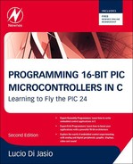
From Table 5.1, taken from the PIC24FJ128GA010 family datasheet, you can see which events can be used to trigger an interrupt.
Table 5.1
Interrupt vector table of the PIC24F GA0 family
| Interrupt Source | Vector Number | IVT Address | Interrupt Bit Locations | ||
| Flag | Enable | Priority | |||
| adc1 Conversion Done | 13 | 00002Eh | IFS0<13> | IEC0<13> | IPC3<6:4> |
| Comparator Event | 18 | 000038h | IFS1<2> | IEC1<2> | IPC4<10:8> |
| crc generator | 67 | 00009Ah | IFS4<3> | IEC4<3> | IPC16<14:12> |
| Extemal Interrupt 0 | 0 | 000014h | IFS0<0> | IEC0<0> | IPC0<2:0> |
| External Interrupt 1 | 20 | 00003Ch | IFS1<4> | IEC1<4> | IPC5<2:0> |
| Extemal Interrupt 2 | 29 | 00004Eh | IFS1<13> | IEC1<13> | IPC7<6:4> |
| Extemal Interrupt 3 | 53 | 00007Eh | IFS3<5> | IEC3<5> | IPC13<6:4> |
| Extemal Interrupt 4 | 54 | 000080h | IFS3<6> | IEC3<6> | IPC13<10:8> |
| 12c1 Master Event | 17 | 000036h | IFS<1> | IEC1<1> | IPC4<6:4> |
| 12c1 Slave Event | 16 | 000034h | IFS1<0> | IEC1<0> | IPC4<2:0> |
| 12c2 Master Event | 50 | 000078h | IFS3<2> | IEC3<2> | IPC12<10:8> |
| 12c2 Slave Event | 49 | 000076h | IFS3<1> | IEC3<1> | IPC12<6:4> |
| Input capture 1 | 1 | 000016h | IFS0<1> | IEC0<1> | IPC0<6:4> |
| Input capture 2 | 5 | 00001Eh | IFS0<5> | IEC0<5> | IPC1<6:4> |
| Input capture 3 | 37 | 00005Eh | IFS2<5> | IEC2<5> | IPC9<6:4> |
| Input capture 4 | 38 | 000060h | IFS2<6> | IEC2<6> | IPC9<10:8> |
| Input capture 5 | 39 | 000062h | IFS2<7> | IEC2<7> | IPC9<14:12> |
| Input change Notification | 19 | 00003Ah | IFS1<3> | IEC1<3> | IPC4<14:12> |
| Output compare 1 | 2 | 000018h | IFS0<2> | IEC0<2> | IPC0<10:8> |
| Output compare 2 | 6 | 000020h | IFS0<6> | IEC0<6> | IPC1<10:8> |
| Output compare 3 | 25 | 000046h | IFS1<9> | IEC1<9> | IPC6<6:4> |
| Output compare 4 | 26 | 000048h | IFS1<10> | IEC1<10> | IPC6<10:8> |
| Output compare 5 | 41 | 000066h | IFS2<9> | IEC2<9> | IPC10<6:4> |
| Parallel master port | 45 | 00006Eh | IFS2<13> | IEC2<13> | IPC11<6:4> |
| Real-Time Clock/Calendar | 62 | 000090h | IFS3<14> | IEC3<13> | IPC15<10:8> |
| spi1 Error | 9 | 000026h | IFS0<9> | IEC0<9> | IPC2<6:4> |
| spi1 Event | 10 | 000028h | IFS0<10> | IEC0<10> | IPC2<10:8> |
| spi2 Error | 32 | 000054h | IFS2<0> | IEC0<0> | IPC8<2:0> |
| spi2 Event | 33 | 000056h | IFS2<1> | IEC2<1> | IPC8<6:4> |
| Timer1 | 3 | 00001Ah | IFS0<3> | IEC0<3> | IPC0<14:12> |
| Timer2 | 7 | 000022h | IFS0<7> | IEC0<7> | IPC1<14:12> |
| Timer3 | 8 | 000024h | IFS0<8> | IEC0<8> | IPC2<2:0> |
| Timer4 | 27 | 00004Ah | IFS1<11> | IEC1<11> | IPC6<14:12> |
| Timer5 | 28 | 00004Ch | IFS1<12> | IEC1<12> | IPC7<2:0> |
| uart1 Error | 65 | 000096h | IFS4<1> | IEC4<1> | IPC16<6:4> |
| uart1 Receiver | 11 | 00002Ah | IFS0<11> | IEC0<11> | IPC2<14:12> |
| uart1 Transmitter | 12 | 00002Ch | IFS0<12> | IEC0<12> | IPC3<2:0> |
| uart2 Error | 66 | 000098h | IFS4<2> | IEC4<2> | IPC16<10:8> |
| uart2 Receiver | 30 | 000050h | IFS1<14> | IEC1<14> | IPC7<10:8> |
| uart2 Transmitter | 31 | 000052h | IFS1<15> | IEC1<15> | IPC7<14:12> |
Among the external sources available for the PIC24FJ128GA010, there are:
• 5×external pins with level trigger detection
• 22×external pins connected to the Change Notification module
• 2×serial port interfaces (UARTs)
And among the internal sources we count:
Many of these sources in their turn can generate several different interrupts. For example, a serial port interface peripheral (UART) can generate three types of interrupts:
• When new data has been received and is available in the receive buffer for processing.
• When data in the transmit buffer has been sent and the buffer is empty and ready and available to transmit more.
• When an error condition has been generated and action might be required to re-establish communication.
Each interrupt source has five associated control bits, allocated in various special-function registers (Table 5.1):
• The Interrupt Enable bit (typically represented with a suffix -IE). When cleared, the specific trigger event is prevented from generating interrupts. When set, it allows the interrupt to be processed. At power on, all interrupt sources are disabled by default.
• The Interrupt Flag (typically represented with a suffix -IF), a single bit of data, is set each time the specific trigger event is activated. Notice how, once set, it must be cleared (manually) by the user. In other words, it must be cleared before exiting the interrupt service routine, or the same interrupt service routine will be immediately called again.
• The Priority Level (typically represented with a suffix -IP). Interrupts can have up to seven levels of priority. Should two interrupt events occur at the same time, the highest-priority event will be served first. Three bits encode the priority level of each interrupt source. The PIC24 execution priority level value is kept in the SR register in three bits referred to as IPL0..IPL2. Interrupts with a priority level lower than the current value of IPL will be ignored. At power on, all interrupt sources are assigned a default level of four and the processor priority is initially set at level zero.
Within an assigned priority level there is also a natural (or default) priority amongst the various sources in the fixed order of appearance in the IVT table.
Nesting of Interrupts
Interrupts can be nested so that a lower-priority interrupt service routine can be, in its turn, interrupted by a higher-priority routine. This behavior can be changed by the NSTDIS bit in the INTCON1 register of the PIC24.
When the NSTDIS bit is set, as soon as an interrupt is received, the priority level of the processor (IPL) is set to the highest level (7) independently of the specific interrupt level assigned to the event. This prevents new interrupts being serviced until the present one is completed. In other words, when NSTDIS bit is set, the priority level of each interrupt is used only to resolve conflicts in the event that multiple interrupts should occur simultaneously. In this case all interrupts will be serviced sequentially.
Traps
Eight additional vectors occupy the first locations at the top of the IVT table (Table 5.2). They are used to capture special error conditions such as a failure of the selected CPU oscillator, an incorrect address (word access to an odd address), stack underflow/overflow or a divide by zero (math error).
Trap Vector Details
Since these types of errors have generally fatal consequences for a running application, they have been assigned fixed priority levels above the seven basic levels available to all other interrupts. This means also that they cannot be inadvertently masked (or delayed by the NSTDIS mechanism) and it provides an extra level of security for the application. The MPLAB C compiler associates all trap vectors to a single default routine that will produce a processor reset. You can change such behavior using the same technique illustrated for all generic interrupt service routines.
A Template and an Example for a Timer1 Interrupt
This all might seem extremely complicated, but we will quickly see that by following some simple guidelines, we can put it to use in no time. Let’s create a template – that we will re-use in future practical examples – that demonstrates the use of the Timer1 peripheral module as the interrupt source. We will start by writing the interrupt service-routine function:
// 1. Timer1 interrupt service routine
void _ISR _T1Interrupt(void)
{// insert your code here
// …
// remember to clear the interrupt flag before exit
_T1IF = 0;
} //T1Interrupt
We used the _ISR macro just like before and made sure to declare the function type and parameters as void. Remembering to clear the interrupt flag (_T1IF) before exiting the function is extremely important, as we have seen. In general, the application code should be extremely concise. The goal of any interrupt service routine is to perform a simple task, quickly and efficiently, in rapid response to an event.
As a general rule, I would say that if you find yourself writing a long interrupt service routine, more than a page of code long (or contemplating calling other functions), you should most probably stop and reconsider the goals and the structure of your application. Lengthy calculations have a place in the main function and specifically in the main loop, not inside an interrupt service routine where time is at premium.
Let’s complete the template with a few lines of code that we will add to the main function:
main()
{// 2. initializations
_T1IP = 4; // this is the default value anyway
TMR1 = 0; // clear the timer
PR1 = PERIOD-1;// set the period register
// 3. configure Timer1 module
T1CON = 0x8020;// enabled, prescaler 1:64, internal clock
// 4. init the Timer1 Interrupt control bits
_T1IF = 0; // clear the interrupt flag, before
_T1IE = 1; // enable the T1 interrupt source
// 5. main loop
while(1)
{
// your main code here
} // main loop
} // main
In 2. we assign a priority level to the Timer1 interrupt source, although this might not be strictly necessary as we know that all interrupt sources are assigned a default level 4 priority at power on. We also clear the timer and assign a value to its period register.
In 3. we complete the configuration of the timer module by turning the timer on with the chosen settings.
In 4. we clear the interrupt flag just before enabling the interrupt source.
The interrupt trigger event for the timer module is defined as the instant the timer value reaches the value assigned to the period register. In that instant, the interrupt flag is set and the timer is reset to begin a new cycle. If the interrupt enable bit is set as well, and the priority level is higher than the processor’s current priority (IPL), the interrupt service function is immediately called.
In 5. we will insert the main loop code. If everything goes as planned, the main loop will execute continuously, interrupted periodically by a brief call to the interrupt service routine.
A Real Example with Timer1
By adding only a couple of lines of code, we can turn this template into a more practical example where Timer1 is used to maintain a real-time clock, with tenths of a second, seconds and minutes. As a simple visual feedback we can use the lower 8 bits of PortA as a binary display showing the seconds running. Here is what we need to add:
Before 1. add the declaration of a few new integer variables that will act as the seconds and minutes counters
int dSec = 0;
int Sec = 0;
int Min = 0;
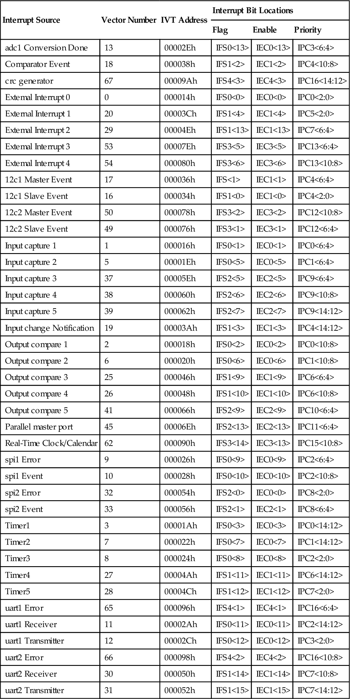
In 1.1. have the interrupt service routine increment the counter: dSec++; a few additional lines of code will be added to take care of the carryover into seconds and minutes.
In 2. set the period register for Timer1 to a value that (assuming a 32 MHz clock) will give us a tenth of a second period between interrupts.
PR1 = 25000−1; // 25,000 * 64 * 1 cycle (62.5ns) = 0.1 s
Set PORTA least significant byte as output:
TRISA = 0xff00;
In 3. set the Timer1 prescaler to 1:64 to help achieve the desired period.
T1CON = 0x8020;
In 3. add code inside the main loop to continuously refresh the content of PORTA with the current value of the milliseconds counter.
PORTA = Sec;
The new project is ready to build:
#include <config.h>
int dSec = 0;
int Sec = 0;
int Min = 0;
// 1. Timer1 interrupt service routine
void _ISR _T1Interrupt(void)
{// 1.1 your code here
dSec++; // increment the tenths of a second counter
if (dSec > 9) // 10 tenths in a second
{
dSec = 0;
Sec++; // increment the seconds counter
if (Sec > 59) // 60 seconds make a minute
{
Sec = 0;
Min++; // increment the minute counter
if (Min > 59)// 59 minutes in an hour
Min = 0;
} // minutes
} // seconds
// 1.2 clear the interrupt flag
_T1IF = 0;
} //T1Interrupt
main()
{// 2. initializations
_T1IP = 4; // this is the default value anyway
TMR1 = 0; // clear the timer
PR1 = 25000−1; // set the period register
TRISA = 0xff00;// set PORTA LSB as output
// 3. configure Timer1 module
T1CON = 0x8020;// enabled, prescaler 1:64, internal clock
// 4. init the Timer1 Interrupt control bits
_T1IF = 0; // clear the interrupt flag, before
_T1IE = 1; // enable the T1 interrupt source
// 5. main loop
while(1)
{
// your main code here
PORTA = Sec;
} // main loop
} // main
Testing the Timer1 Interrupt
Let’s first build the project for debugging using the Debug>Debug Project command from the main menu.
Then let’s open the Watches window selecting Debug>New Watch… from the main menu (or pressing CTRL+SHIFT+F7) then add the following variables:
• dSec: select from the Symbol pull down box, then click on Add
• TMR1: select from the SFR pull down box, then click on Add
Now let’s set a breakpoint: set the cursor on the first line of the Timer1 interrupt service routine (1.1) and right click with the mouse and select Toggle Line Breakpoint.
Alternatively you can press CTRL+F8 or perhaps, even more simply, you can click with your mouse pointer right on the line number in the editor gutter, that gray area on the immediate left border of the editor window. In either case, a little red square will be superimposed on the line number and the whole line will be highlighted in red as in Figure 5.1.

By setting a breakpoint here, we will be able to observe whether the interrupt is actually being triggered.
Start executing the code by pressing the Continue button ![]() (or select Debug>Continue). The debugger should stop quickly, with the program counter cursor (the green bar) pointing right at the breakpoint inside the interrupt service routine (Figure 5.2).
(or select Debug>Continue). The debugger should stop quickly, with the program counter cursor (the green bar) pointing right at the breakpoint inside the interrupt service routine (Figure 5.2).
So we did stop inside the interrupt service routine! This means that the trigger event was activated; that is, the Timer1 reached a count of 24,999 (0x61A7). Remember though that the Timer1 count starts with 0, therefore 25,000 counts have been performed, which multiplied by the prescaler value means that 25,000×64 or exactly 1.6 million cycles have elapsed. At the PIC24’s execution rate (16 million instructions per second or 62.5 ns per cycle) this all happened in a tenth of a second!
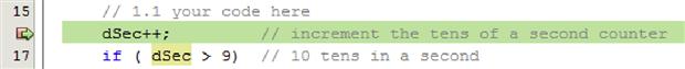
From the Watches window we can now observe the current value of processor priority level (IPL). Since we are inside an interrupt service routine, configured to operate at level 4, we should be able to verify that bits 3, 4 and 5 of the status register (SR) contain exactly this value. For maximum convenience, click on the little plus sign icon next to the line of the Watches window that shows the value of the SR register to expand it and show the individual bit fields contained.
In Figure 5.3, I have circled the IPL (bitfield) value in the Watches window showing that an interrupt priority level four is being serviced.
Single stepping from the current position, using either the StepOver or the StepIn commands, we can monitor the execution of the next few instructions inside the interrupt service routine. Upon its completion, we can observe how the priority level returns back to the initial value – look for the IPL bit field to be cleared.
After executing another Continue command, we should find ourselves again in the interrupt routine, and another 1.6 million cycles will have been executed.
Add the Sec and Min variables to the Watches window.
Execute the Continue command a few more times to verify that, after 10 iterations, the seconds counter is incremented.
To test the minutes, you might want to remove the current breakpoint and place a new one a few lines below – otherwise you will have to execute the Continue command exactly 600 times!
Place the new interrupt on the Min++ statement.
Execute the Continue command once more and while you wait watch the LED bar count in binary all the way to 0x3B (59). Now observe that the seconds counter has already been cleared in the Watches window, but the new value has not been updated yet on the LED bar.
Execute the Step Over command once and the minute counter will be incremented.
The interrupt routine has been executed 600 times in total, at precise intervals of one tenth of a second. Meanwhile the code present in the main loop has been executed continuously to use the vast majority of the grand total of 960 million cycles. In all honesty, our demo program did not make much use of all those cycles, wasting them all in a continuous update of the PortA content. In a real application, we would have performed a lot of work, all the while maintaining a precise real-time clock count.
The Secondary Oscillator
There is another feature of the PIC24 Timer1 module (common to all previous generations of 8-bit PIC® microcontrollers) that we could have used to obtain a real-time clock. In fact, there is a low-frequency oscillator, known as the secondary oscillator, that can be used to feed just the Timer1 module in place of the high-frequency main clock. Since it is designed for low-frequency operation, typically it is used in conjunction with an inexpensive 32,768 Hz crystal, it requires very little power to operate. And since it is independent of the main clock circuit, it can be maintained in operation when the main clock is disabled and the processor enters one of the many possible low-power modes. In fact, the secondary oscillator is an essential part of many of those low-power modes. In some cases it is used to replace the main clock, in others it remains active only to feed the Timer1 or a selected group of peripherals.
To convert our previous example for use with the secondary oscillator, we will need to perform only a few minor modifications, such as:
• Change the interrupt routine to count only seconds and minutes (the much slower clock rate does not require the extra step for the tenth of a second).
// 1. Timer1 interrupt service routine
void _ISR _T1Interrupt(void)
{// 1.1 clear the interrupt flag
_T1IF = 0;
// 1.2 your code here
Sec++; // increment the seconds counter
if (Sec > 59) // 60 seconds make a minute
{
Sec = 0;
Min++; // increment the minute counter
if (Min > 59)// 59 minutes in an hour
Min = 0;
} // minutes
PR1 = 32768−1; // set the period register
T1CON = 0x8002; // T1 on, 1:1 off secondary oscillator
According to the PIC24 datasheet, to activate the secondary low-power oscillator you will also need to set the SOSCEN bit in the OSCCON register. But before you rush to type in the code and try to execute it on the target board, notice that the OSCCON register contains vital controls for the MCU affecting the choice of the main active oscillator and its speed (Figure 5.4).
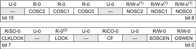
Because of its importance, it is protected by a locking mechanism. As a safety measure, you will have to perform a special unlock sequence first or your command will be ignored. The sequence would be hard, if not impossible, to code in C. Even if we managed, the optimizer could disrupt it later. So there are only two options: use inline assembly language or, better, use a built-in function of the MPLAB C compiler for the PIC24.
__builtin_write_OSCCONL(2);
This function does perform the required unlock sequence and writes the desired value “2” to set the SOSCEN bit in the OSCCON register for us.
Now we are finally ready. Remove all the breakpoints, then re-build the project. This time elect to use the Run mode: select Run>Run Project. You will be able to quickly verify that the LED bar is being updated once a second as desired. The difference is that here the timing is independent of the main clock frequency, which could change or could be generated by a low-accuracy clock source such as the fast (8 MHz) internal oscillator (FRC) of the PIC24.
The Real-Time Clock Calendar (RTCC)
Building on the previous two examples, we could evolve the real-time clock implementations to include the complete functionality of a calendar, adding the count of days, day of the week, months and years. These few new lines of code would be executed only once a day, once a month or once a year, and therefore would produce no decrease in the performance of the overall application whatsoever. Although it would be somewhat entertaining to develop such code, considering leap years and working out all the details, the PIC24FJ128GA010 already has a complete Real-Time Clock and Calendar (RTCC) module built in and ready for use.
How convenient! Not only is it fed from the same low-power secondary oscillator, but it comes with all the bells and whistles – including a built in Alarm function that can generate interrupts. In other words, once the module is initialized, it is possible to activate the RTCC alarm and wait for an interrupt to be generated, for example, on the exact month, day, hour, minute and second desired once a year (or, if set on February 29th, even once every four years!).
Setting the RTCC time requires a similar combination lock mechanism (as seen with OSCCON) to protect the key RTCC register RCFGCAL. A special bit (RTCWEN) must be set to allow writing to the register, but this bit requires its own special unlock sequence to be executed first. Here another built-in function of the MPLAB C compiler for the PIC24 comes to our rescue:
__builtin_write_RTCWEN();
This time, no parameter is required. The unlock sequence for the RTCC register is performed and the RTCWEN bit is set.
After this step, initializing the RTCC, setting the date and time is trivial:
_RTCEN = 0; // disable the module
// example set 12/01/2006 WED 12:01:30
_RTCPTR = 3; // start the loading sequence
RTCVAL = 0x2006; // YEAR
RTCVAL = 0x1100; // MONTH-1/DAY-1
RTCVAL = 0x0312; // WEEKDAY/HOURS
RTCVAL = 0x0130; // MINUTES/SECONDS
// optional calibration
//_CAL = 0x00;
// enable and lock
_RTCEN = 1; // enable the module
_RTCWREN = 0; // lock settings
Setting the alarm does not require any special unlock combination. Here is an example that will help you remember my birthday:
// disable alarm
_ALRMEN = 0;
// set the ALARM for a specific day (my birthday)
_ALRMPTR = 2; // start the loading sequence
ALRMVAL = 0x1124; // MONTH-1/DAY-1
ALRMVAL = 0x0006; // WEEKDAY/HOUR
ALRMVAL = 0x0000; // MINUTES/SECONDS
// set the repeat counter
_ARPT = 0; // once
_CHIME = 1; // indefinitely
Now all you need to do is to set up the Alarm Mask as in:
_AMASK = 0b1001; // set alarm once a year
And enable the alarm and RTC interrupt in place of the Timer1 interrupt:
_ALRMEN = 1; // enable alarm
_RTCIF = 0; // clear interrupt flag
_RTCIE = 1; // enable interrupt
Finally, this is what the interrupt service routine will look like…
// 1. RTCC interrupt service routine
void _ISR _RTCCInterrupt(void)
{// 1.1 clear the interrupt flag
_RTCIF = 0;
// 1.2 your code here, will be executed only once a year
// or once every 365 x 24 x 60 x 60 x 16,000,000 MCU cycles
// that is once every 504,576,000,000,000 MCU cycles
} // RTCCInterrupt
Managing Multiple Interrupts
It is typical of an embedded control application to require several interrupt sources to be serviced. For example, a serial communication port might only require periodic attention, while a PWM might require periodic updates to control an analog output. Multiple timer modules might be used simultaneously to produce pulsed outputs, while multiple inputs could be sampled by the Analog to Digital converter and their values would need to be buffered. There is no limit to the number of things that can be done with 118 interrupt sources available. At the same time, there is no limit to the complexity of the bugs that can be generated thanks to the same sophisticated mechanisms if a little discipline and some common sense are not applied.
Here are some of the rules to keep in mind:
1. Keep it short and simple. Make sure the interrupt routines are the shortest/fastest possible, and under no circumstances should you attempt to perform any processing of the incoming data. Limit the activity to buffering, transferring and flagging.
2. Use the priority levels to determine which event deserves to be serviced first, in case two events are triggered simultaneously.
But consider very carefully whether you want to face the additional complexity and headaches that result from enabling the use of nested interrupt calls. After all, if the interrupt service routines are short and efficient, the extra latency introduced by waiting for the current interrupt to be completed before a new one is serviced is going to be extremely small. If you determine that you don’t really need it, make sure the NSTDIS control bit is set to prevent nesting:
_NSTDIS = 1; // disable interrupt nesting (default)
Post-Flight Briefing
In this lesson we have seen how an interrupt service routine can be simple to code thanks to the language extensions built into the MPLAB C compiler, and the powerful interrupt control mechanisms offered by the PIC24 architecture. Interrupts can be an extremely efficient tool in the hands of the embedded-control programmer to manage multiple tasks while maintaining precious timing and resources constraints. At the same time, they can be a great source of trouble. In the PIC24 reference manual and the MPLAB C Compiler User Guide you will find more useful information than we could possibly cram into one single lesson. Finally, in this lesson we took the opportunity to learn more about the uses of Timer1 and the secondary oscillator, and we got a glimpse of the features of the new Real-Time Clock and Calendar (RTCC) module.
Notes for the C Experts
The interrupt vector table (IVT) is an essential part of the crt0 code segment for the PIC24. Actually, two copies of it are required to be present in the first 256 locations of the program memory. One is used during normal program execution, and the second (or Alternate IVT) during debugging. These tables account for most of the size of the crt0 code in all the examples we have been developing in these first five lessons. Subtract 256 words (or 768 bytes) from the file size of each example to obtain the “net” code size.
Notes for the Assembly Experts
The _ISRFAST macro can be used to declare a function as an interrupt service routine and to further specify that it will use an additional and convenient feature of the PIC24 architecture: a set of four shadow registers. By allowing the processor to automatically save the content of the first four working registers (W0–W3, i.e. the most frequently used ones) and most of the content of the SR register in special reserved locations, without requiring the use of the stack, the shadow registers provide the fastest possible interrupt response time. Naturally, since there is only one set of such registers, their use is limited to applications where only one interrupt will be serviced at any given time. This does not limit us to use only one interrupt in the entire application, but rather to use _ISRFAST only in applications that have all interrupts with the same priority level or, if multiple levels are in use, reserve the _ISRFAST options only for the interrupt service routines with the highest level of priority.
Notes for the PIC Microcontroller Experts
It is about time that we start using more of the PIC24 peripheral libraries. In the previous chapters I have often specifically avoided them to illustrate the need for the embedded control programmer to understand the minute details of the microcontroller architecture and, to a degree, to allow those readers transitioning from assembly language to appreciate how even C language can be close to the “machine”.
Libraries (collections of ready to use functions) can speed up considerably the development of a project by hiding complex details and exposing simple-to-use interfaces. In fact, in the next few chapters we will start developing our own little library (moving new modules in the /lib subdirectory and their corresponding headers in the /include subdirectory) to simplify a multitude of interesting applications.
But libraries can also obscure your code and make debugging very difficult if they are not very well designed and documented. For this reason, I am very selective when choosing to use function libraries in my applications and in the rest of this book.
Although Microchip offers a peripheral library for the PIC24 that contains a module for each peripheral contained in each device family, not all of them are equally useful!
For example, the ports.h library offers hundreds of functions (and macros) to perform the simplest of the operations on the I/O pins of the PIC24, such as:
mPORTBRead()
As you would have guessed, this macro reads the contents of the PORTB register.
What do you think the following function does then?
mPORTACloseAll()
Closing a Port is not a defined operation, not documented at least in the general Microchip literature, so you will be hard pressed to guess what will really be accomplished.
As a consequence, generally I do not recommend using the ports.h library but, rather, I encourage my readers to use the Port registers directly. There is absolutely no advantage in using the library form over the register name.
A different case can be made for the RTCC peripheral. The rtcc.h library does offer very useful functions that do simplify the configuration and use of the real-time clock and calendar. For example, the following two functions can quickly enable the secondary oscillator, turn on the RTCC and enable its configuration:
RtccInitClock();
RtccWrOn(); // unlock and enable writing to RTCC
Setting the date and time of day becomes an equally simple task with the following code:
rtccTimeDate TD = { 0x06, 0x20, // year
0x01, 0x11, // day, month
0x12, 0x03, // hour, weekday
0x30, 0x01};// sec, min
RtccWriteTimeDate(&TD, FALSE);
Perhaps even more interesting is how the alarm mask definition is simplified:
RtccSetAlarmRpt(RTCC_RPT_YEAR, TRUE);
As a pro, consider how, instead of setting the AMASK register to a cryptic binary value, we can use a self-explanatory constant: RTCC_RPT_YEAR to decide when the alarm match should trigger our next interrupt.
As a con though, consider that the RTCC_RPT_YEAR constant is not documented in the device datasheet but only in the rtcc.h header file (and simply listed in the help file .chm). Once you find it, you will be hard pressed to make sure to match it to the desired pattern of bits in the AMASK register as per the device datasheet.
In the next few chapters we will see more such examples of use of the peripheral libraries and in the end I will let you decide how and when you want to take things in your own hands and when you will want to trust the libraries to do things for you.
On the companion website (www.flyingpic24.com) you will find multiple versions of the examples presented in this and many of the following chapters where the peripheral libraries have been used in place of direct access to the registers (i.e. alarm.c and alarm-p.c). By comparing them side by side, you will be able to judge for yourself the pros and cons of both approaches.
Tips & Tricks
• As of version 3.0 of the MPLAB C compiler, a new attribute has been added (required) to the interrupt service routines declaration to specify whether the PSV window pointer save and restore should be managed by the compiler (see the next chapter to learn more about the PSV). Since in all the example applications presented in this book we will not modify the PSV window pointer, we will redefine the _ISR and _ISR_FAST macros to add the new no_auto_psv attribute automatically to all our interrupt service routine declarations.
#if __C30_VERSION__ >= 300
#undef _ISR
#define _ISR __attribute__((interrupt,no_auto_psv))
#undef _ISRFAST
#define _ISRFAST __attribute__((interrupt,shadow,no_auto_psv))
We could place this code in the config.h header file but, since we will be soon using interrupts in multiple library modules, we will instead include it in the EX16.h where since lesson 3 (Tips & Tricks) we have been assembling all things specific to the Explorer16 demonstration board.
/*
** EX16.h
**
** Standard definitions for use with the Explorer16 board
*/
#ifndef _EX16
#define _EX16
#include <p24fxxxx.h>
#if __C30_VERSION__ >= 300
#undef _ISR
#define _ISR __attribute__((interrupt,no_auto_psv))
#undef _ISRFAST
#define _ISRFAST __attribute__((interrupt,shadow,no_auto_psv))
#endif
#define FCY 16000000UL // instruction clock 16 MHz
#define USE_AND_OR // use OR to assemble control register bits
#define _FAR __attribute__((far))
// prototypes
void InitEX16(void); // initialize the Explorer16 board
• On the PIC24 architecture there is no single control bit that disables all interrupts, but there is an instruction (DISI) that can disable interrupts for a limited number of cycles. If there are portions of code that require all interrupts to be temporarily disabled, you can use the following inline assembly command:
__asm__ volatile("disi #0x3FFF"); // disable temporarily all interrupts // your code here// …
DISICNT = 0; // re-enable all interrupts
Exercises
Books
• Brown, G., 2003. Flying Carpet, The Soul of An Airplane, Iowa State Press, Ames, IO.
Greg has many fun episodes from the real life of a general aviation pilot who uses his plane for recreation as well as a family utility.
• Curtis, K.E., 2006. Embedded Multitasking, Newnes, Burlinghton, MA.
Keith knows multitasking and what it takes to create small and efficient embedded control applications.
Links
This is the web site of the Aircraft Owners and Pilot Association. Feel free to browse through the web site and access the many magazines and free services offered by the association. You will find a lot of useful and interesting information in here.
• http://www.niell.org/nixie_clock/Nixieclock.html
A PIC-based clock with a retro style, using glowing Nixie tubes.