
Visual Studio 2008 offers several windows that document class hierarchies and show relationships between classes, including inheritance. The Class View, Object Browser, and Class Diagram windows are examples. The Class View and Object Browser windows have been available for some time, but the Class Diagram window was introduced in Visual Studio 2005.
The Class View window provides a visual representation of the types included in the projects of the current solution. Expand the project and then expand class nodes to display the class hierarchy. Each item in the class hierarchy has a context menu with helpful commands. For example, use the context menu to render classes in a class diagram. The Class View window even shows external classes from referenced applications. Open the Project References folder to find external classes. For example, many of the FCL classes will be found in this folder. Figure 4-12 shows the Class View window, including the Project References folder. If the Class View window is closed, you can open it by selecting Class View from the View menu.
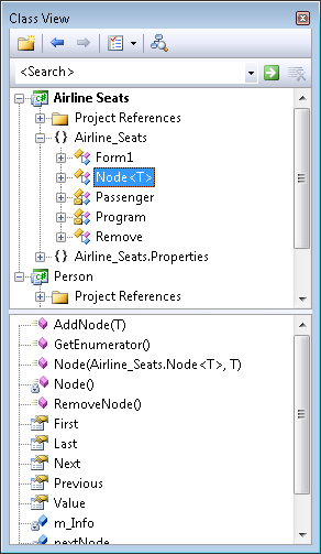
The Class View window has two panes. The top pane contains the hierarchy, whereas the bottom pane displays the details of whatever type is selected. The bottom pane presents information about a type, such as its members. Across the top of the Class View window are five icons: Class View New Folder, Back, Forward, Class View Settings, and View Class Diagram. Beneath these icons is the Search combo box, which is used to search the hierarchy for a symbol. This is especially helpful with extensive class hierarchies. Type the search text and press Enter to initiate a search. All symbols—such as classes, methods, fields, and properties—that contain some part of the search text are returned in the Class View window.
The Object Browser window (shown in Figure 4-13) offers similar information as the Class View window. The Object Browser displays the class hierarchy of the current project and referenced applications, such as the system libraries. If the Object Browser is not visible, open it by selecting Object Browser from the View menu.
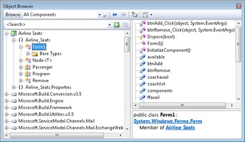
The Object Browser contains three panes. The left pane has the class hierarchy. The remaining two panes are vertically aligned on the right of the window. The top pane on the right lists the members of the item selected in the class hierarchy. (Members are not listed for namespaces.) A description of the selected item is found in the bottom pane. The Object Browser toolbar has the Choose Object Browsing Scope, Edit Custom Component Set, Back, Forward, Add To References, and Object Browser Settings buttons. The Browser Scope button filters the class hierarchy. You can display classes from the current solution, custom component set, .NET Framework, or all classes. Load another application into the Object Browser using the Edit Custom Component Set button. The imported information is found in the Custom Component Set scope of the Object Browser window. The Add To References button adds a reference to an application to this project. For example, you can add references from items listed at the Edit Custom Component Set scope. Use the Search box below the toolbar to enter and find specific information in the class hierarchy.
Class diagrams were introduced in Visual Studio 2005. Developers can model object-oriented applications using class diagrams. Class diagrams present a visual representation of a type and type hierarchy. It’s important to note that class diagrams are not static. Developers can add new types, create new relationships, insert members, delete members, and much more. In addition, the class diagram is synchronized with the source code of the application. Changes to types modeled in the class diagram are immediately updated in the affected code. Conversely, changes in the source code immediately appear in a relevant class diagram. Therefore, the code base and diagram dynamically remain in sync. Updated design documents are one of the seminal benefits of the class diagram. Where do design documents disappear to after the project has started? This problem frequently plagues developers of object-oriented applications. For many applications in the past, original design documents were not available or were not updated as the project progressed. Stale design documents sometimes are worse than nothing. They are definitely more misleading. Class diagrams help keep design documents current. With the class design, the design and implementation phase is truly iterative, which translates into better-developed applications. You also can preserve diagrams at important milestones, which then can be examined in source control for posterity. Class diagrams are preserved as snapshots. From the Class Diagram menu, choose the Export Diagram As Image command.
Class diagrams provide a high-level perspective of an application, which is beneficial throughout the life cycle of the application. This is particularly useful in complex systems, where there can be hundreds of classes and relationships. In projects of this size, it is easy to get lost in the details. Class diagrams provide visual clarity that windows such as the Class View window cannot present. Class diagrams start as an abstracted view, where introspection is available as needed.
You control how much or little information is presented in the class diagram. You can view one class, a dozen types, or everything in the class diagram. Relationships between types, such as inheritance and association, also can be shown. In addition, separate class diagrams can be created to group-related types or simply to reduce the amount of information presented in a single diagram.
In Visual Studio 2008, there are several ways to create a class diagram. One way is to select the Add New Item command from the Project menu. In the Add New Item dialog box, choose Class Diagram. In the Name text box, name the class diagram. (Class diagram files are given the .cd file extension automatically.) You also can open a new class diagram from the Solution Explorer or Class View window. In Solution Explorer, right-click the project or source file and then choose View Class Diagram. This creates a new class diagram that contains all the classes found in the project or source file. In Class View, right-click a namespace or class and choose View Class Diagram from the context menu.
Class diagrams have a surface. There are several ways to add existing or new types to this surface:
Drag a type from the Class View window or the Object Browser to the class diagram surface.
Drag a file from Solution Explorer to the class diagram surface. All classes in the file will be added to the class diagram.
Add a new type from the Class Designer toolbox.
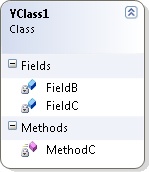
Figure 4-14 shows a class diagram with a single class on the surface. The class is contained in a shape that has a header across the top and a details pane below that. Click once on the label in the header to change the name of the class. Double-click the header to view the source code related to that shape (type). There is also an expand button or collapse button. The expand button is the double-down arrow and shows the details of the type, such as the members. The collapse button is the double-up arrow and hides the details of the type. The expand and collapse buttons toggle, depending on whether the details are visible or not.
In addition to adding shapes, you can remove types from a class diagram. To do this, select the shape for the target type, right-click the header, and select Remove From Diagram. The type is removed from the diagram, but it remains in the program. An easier method of removing a class from the diagram is simply to select the type and then press the Delete key. Doing this is similar to using the Remove From Diagram command. The Delete Code option is different in that it not only removes the class from the class diagram, but it also deletes it from the project.
You also can view, change, delete, add, hide, or unhide members of the type. The Hide command hides a member. Right-click the item and choose Hide. Hidden members can be shown with the Show All Members command, found on the context menu when you right-click the shape header.
The Class Details window shows the members of the class. Members are grouped by category (fields, methods, properties, and other member types). Each group can be collapsed or expanded. Members also can be viewed and managed in the Class Details window, as shown in Figure 4-15. If the Class Details window is not visible, display it by right-clicking anywhere on the shape and choosing Class Details.
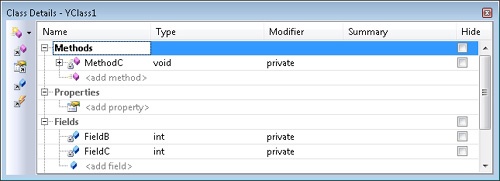
In the Class Details window, you can change the name, type, or accessibility of a member. The Class Details toolbox has five buttons. The New <member> button adds a Method, Property, Field, Event, Constructor, Destructor, or Constant to a class. The Navigate To Methods button navigates to the Methods section in the Class Details window. This is helpful for large classes that have dozens of members, or even more. The final three buttons are Navigate to Properties, Navigate to Fields, and Navigate to Events.
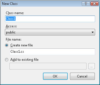
Class diagrams have a toolbox, as shown in Figure 4-16. The topmost buttons of the toolbox add new types to the class diagram and application. You can add a new class, enumeration, interface, abstract class, structure, or delegate. Double-clicking one of these "new type" buttons adds the new type to the application, and the new type then is displayed in the class diagram. Alternatively, you can drag the button from the toolbox onto the class diagram surface to add the new type. The New Class dialog box is displayed when a new type is added. (See Figure 4-17.) The type name, accessibility, and file name can be entered in the dialog box.
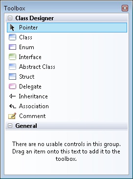
The Inheritance and Association buttons appear below the New Type button on the toolbox. The Inheritance button creates an inheritance line, which links a base class and a derived class. You draw the inheritance line from the derived type to the parent type to define inheritance. The Association button creates an association line that defines the relationship between an embedded class and an outer class. Drag the association line from the outer class to the embedded class. The Comment button is the last item in the toolbox and adds comments to the class diagram.
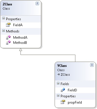
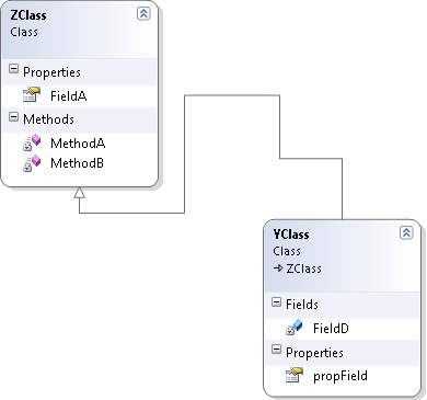
Inheritance is shown in the class diagram. Inheritance lines depict the base-to-derived-type relationship. Implicit inheritance of System.Object and System.ValueType is not shown in the class diagram. Figure 4-18 shows how class inheritance is depicted in a class diagram. In the figure, YClass inherits from the ZClass class. The inheritance line has a triangular arrowhead pointing to the base class. The other end of the arrow originates at the derived class. Select and then delete the inheritance line to remove the inheritance relationship. Alternatively, you can remove the inheritance line by right-clicking the inheritance line and selecting Delete Code.
You can create new base-to-derived-class relationships in the class diagram. Select the Inheritance button in the toolbox. Click anywhere in the derived class and drag the inheritance line from the derived to the base class. (In the initial release of Visual Studio 2008, you might have to switch to a different application and back after clicking the Inheritance button to use the Inheritance tool.) This assumes that both the base and derived classes are already on the class diagram.
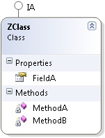
Interface and class inheritance are manipulated similarly in the class diagram. Add interface inheritance to a type using the Inheritance button in the toolbox. Visual Studio automatically stubs the interface members in the derived type. In the Code Editor, developers can replace the stubs with the appropriate implementation. Interface inheritance is not depicted as an inheritance line. Instead, interface inheritance is displayed as a lollipop atop the derived type. This is shown in Figure 4-19, in which ZClass inherits the IA interface.
Relationship lines, which are both inheritance and association lines, can be rerouted within a diagram simply by selecting and dragging the lines. Rerouting lines can fix poorly drawn class diagrams. Lines can be rerouted multiple times and additional nodes (segments) added. Figure 4-20 shows a rerouted inheritance line. Dragging either endpoint of a line repositions the relationship line on the target shape. The mouse cursor looks like a cross when positioned correctly over the end point of a relationship line. The context menu of a relationship line has a Reroute command, which reroutes the relationship line automatically for you. This assumes that there is a better path to which the line can be routed.
The class diagram can locate the base or derived class of a type. Right-click a shape header to open the context menu. The Show Base Class command selects the base class in the class diagram. Conversely, choose Show Derived Classes to highlight derived classes. If the base or derived class is not already in the class diagram, the class is added automatically.
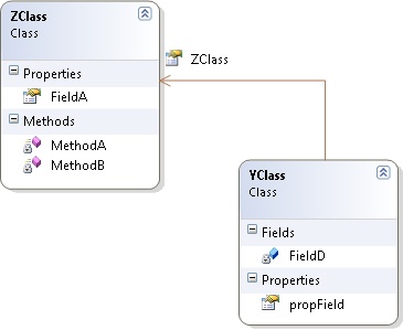
Association lines define a "has-a" relationship, where one type has a member that is another type. The inner type is embedded as a property. Figure 4-21 shows an association relationship in a class diagram. In the figure, the YClass class has a member of the ZClass type embedded as a property. The association line looks slightly different from the inheritance line. Association lines have an open arrowhead pointing to the embedded type.
To create a new relationship in a class diagram, select the Association button in the toolbox. Click the outer type and drag the association line from the outer type to the inner (embedded) type. (In the initial release of Visual Studio 2008, you might have to switch to a different application and back after selecting the Association button to use the Association tool.) In the outer type, a property of the inner type is added. You then can switch to the Code Editor and implement the property, which should return an instance of the inner type. For example, if you drag the association line from ZClass to XClass, XClass will be the inner type. A property will be added to ZClass. That property should return an instance of XClass.
When the association line is visible, the related property is not shown in the details of the shape belonging to the outer type. Alternatively, you can show the association as a property and remove the association line. Right-click the association line and select the Show As Property command. To reverse this behavior, right-click the property and select Show As Association. (If the embedded type is not displayed, Visual Studio will add it to the diagram.)
The following example demonstrates the use of the class diagram—particularly in creating new types and relationships:
Create a new class library. In Visual Studio 2008, choose New from the File menu, then choose Project to create a new project. You also can accomplish this by clicking New Project on the Standard toolbar. Select the Visual C# node in the Project Types pane and then select the Class Library template. Name the project Personnel.
Add a class diagram to the project. Open the Project menu and select Add New Item. In the Add New Item dialog box, add a class diagram. Name the class diagram Employee.
Add a new interface using the class diagram toolbox. Name the interface IEmployee. Accept the remaining defaults for the interface.
Add a new abstract class using the class diagram toolbox. Name the class Employee. Accept the remaining defaults for the class.
Add another class using the class diagram toolbox. Name this class HourlyEmployee. Accept the remaining defaults for the class.
Add a new struct using the class diagram toolbox. Name the struct Name. Accept the defaults. Structs are depicted in the class diagram as rectangles with square corners.
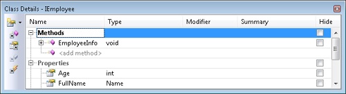
From the Class Details window, add three members to the IEmployee interface: the EmployeeInfo method, the Age property, and the Fullname property. (See Figure 4-22.) The EmployeeInfo method returns a string. The Age property is an integer and gets and sets the age of an employee. Finally, the Fullname property is of the Name type and returns the employee name.
The Employee class should inherit and implement the IEmployee interface. Select the Inheritance button in the class diagram toolbox. Click the Employee class and drag the inheritance line from the Employee class to the IEmployee interface. The interface members now appear in the class details of the Employee class. In addition, Employee is given the stubbed implementations of the interface members:
public abstract class Employee : IEmployee
{
    #region IEmployee Members

    public int Age
    {
        get
        {
            throw new Exception(
                "The method or operation is not implemented.");
        }
        set
        {
            throw new Exception(
                "The method or operation is not implemented.");
        }
    }

    // Partial listing
}
Derived types of the Employee class must have a calculate pay operation. Add an abstract CalculatePay method to the Employee class. (The method returns a decimal.) To do so, right-click the header of the Employee class. From the context menu, select Add and then select Method . Name the new method CalculatePay. In the Class Details window, set decimal as the return type. The method should be abstract, so double-click the header to view the source code for the method, then replace the body with a semicolon (;) and change the method to abstract.
The HourlyEmployee class should inherit the Employee class. This relationship is created with the Inheritance button in the toolbox. Click the HourlyEmployee class and drag the inheritance line from the HourlyEmployee class to the Employee class.
Finally, add a Pay method to the HourlyEmployee class. (The Pay method has a single parameter, which is the hours worked.) In the Class Details window, expand the row for the Pay method to expose the Add Parameter item. Select the Add Parameter row and enter Hours as the parameter name. Change the parameter’s type to decimal. To complete the class, add an HourlyRate property to the class as a decimal type.
The Name struct has two string properties: FirstName and LastName. Both properties can be added in the Class Details window.
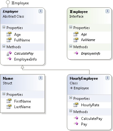
The final class diagram for the Personnel application is shown in Figure 4-23.
The following code is generated for the class diagram. The functions are stubbed. Implementing the stubbed methods is the only remaining step. You might have to add the keyword override to the CalculatePay method.
public interface IEmployee
{
    int Age
    {
        get;
        set;
    }

    Name Fullname
    {
        get;
        set;
    }

    string EmployeeInfo();
}

public struct Name
{
    public string FirstName
    {
        get
        {
            throw new System.NotImplementedException();
        }
        set
        {
        }
    }

    public string LastName
    {
        get
        {
            throw new System.NotImplementedException();
        }
        set
        {
        }
    }
}

public abstract class Employee : IEmployee
{
    #region IEmployee Members

    public int Age
    {
        get
        {
            throw new NotImplementedException();
        }
        set
        {
            throw new NotImplementedException();
        }
    }

    public Name Fullname
    {
        get
        {
            throw new NotImplementedException();
        }
        set
        {
            throw new NotImplementedException();
        }
    }

    public string EmployeeInfo()
    {
        throw new NotImplementedException();
    }

    #endregion

    public abstract decimal CalculatePay();
}

public class HourlyEmployee : Employee
{
    public decimal HourlyRate
    {
        get
        {
            throw new System.NotImplementedException();
        }
        set
        {
        }
    }

    public override decimal CalculatePay()
    {
        throw new System.NotImplementedException();
    }

    public void Pay(decimal Hours)
    {
        throw new System.NotImplementedException();
    }
}The Error List window (shown in Figure 4-24) displays errors and warnings as you type in the Code Editor window, from the compiler, and from the linker. Each type of message has a unique icon. For example, an error message is decorated with a red circle that contains an "x". If the window is not open, you can display it by selecting Error List from the View menu.
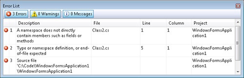
In the Error List window, the Errors, Warnings, and Messages buttons hide or show categories of messages. These buttons indicate the number of messages for each category. Click the buttons to filter messages of that category. In addition, you can use the column headers to sort the error list. Column headers can be dragged horizontally to change column order. For each error, the error number, description, and location are shown in the window. Double-clicking a specific error or warning message in the error list opens the Code Editor window and shows the pertinent source code.