
Chapter Goal: Build a Portable IOT Device for Reading Your Pulse
Topics Covered in This Chapter:
IOT on a Global Network
Bluemix and the Internet Of Things
The IOTPulse Design
Building the IOTPulse Device
Connecting and testing the hardware and software for IOTPulse
Setting up IBM Bluemix and Connecting IOTPulse
Examining Results and Advanced Features
This chapter will show the reader how to connect an IOT device to a cloud server, IBM Bluemix. The complexity in this chapter is not building the device, but rather navigating the setup process for adding your device to the cloud.
A major part of designing devices that will connect with the IOT is to determine what to do with the data after you have gathered it. A huge amount of data and no way to store it or analyze it is not very useful. An IOT project device generally is very CPU limited and also only has a limited amount of storage available. You generally have to send the data collected by a sensor-filled IOT device up to a bigger computer and storage cloud to perform complex analysis and determine actions on that data.
In this chapter, we are building a device to collect the pulse rate from a person, and then periodically (every 10 seconds) send it up to a cloud-based storage and analysis system called the IBM Bluemix IOT Foundation.
Before we selected the IBM Bluemix for this chapter, we also looked at three other providers. We determined that the Amazon IOT solution was too “heavy” for these small devices because of the protocol and encryption required. The two other smaller vendors were rejected because of length of time in existence and limited analysis functionality. It should be pointed out that the smaller vendors had distinctly superior display capabilities out of the box from either of the two majors.
The IBM Bluemix system brought a good mix of flexible protocols, a “light” method for sending data, and an amazing collection of analytical tools. Ramifications of the IBM Bluemix methodology on encryption versus the Amazon IOT solution will be discussed in Chapter 7, “Computer Security and the IOT.”
IOT Characterization of This Project
As we discussed in Chapter 1, the first thing to do to understand an IOT project is to look at our six different aspects of IOT shown in Table 5-1. IOTPulse is a more complex project than LightSwarm and is much closer to a production IOT device.
Table 5-1. IOTPulse Characterization (CPLPFC )
Aspect | Rating | Comments |
|---|---|---|
Communications | 9 | WiFi connection to Internet - |
Processor Power | 7 | 80MHz XTensa Harvard Architecture CPU, ∼80KB Data RAM / ∼35KB of Instruction RAM / 200K ROM |
Local Storage | 8 | 4MB Flash (or 3MB file system!) |
Power Consumption | 8 | ∼200mA transmitting, ∼60mA receiving, noWiFi ∼15mA, Standby ∼1mA |
Functionality | 7 | Partial Arduino Support (limited GPIO/Analog Inputs) |
Cost | 9 | < $10 and getting cheaper |
Ratings are from 1–10, 1 being the least suitable for IOT and 10 being the most suitable for IOT applications.
This gives us a CPLPFC rating of 8.0. Great for learning and experimenting, and it could be deployed for some market applications.
The ESP8266 provides a WiFi transmitter/receiver, a TCP/IP stack, and firmware to support direction connections to a local WiFi access point, which then can connect to the Internet. The data generated by the IOTPulse design will be sent to IBM’s Bluemix Cloud IOT site.
The Internet Of Things on the Global Network
As was stated in the introduction, what do you do with all this data you are gathering? Whether it is the age of your milk in the refrigerator, your current blood sugar or pulse rate, or your home security system, the data needs to be stored and analyzed; or what is the point of gathering it?
Sometimes you don’t need to store the data. Sometimes the local devices can do the necessary actions (like in the LightSwarm project in Chapter 2), but there are many applications that require more computing resources than might be available among the local IOT devices.
This is the situation that has led to the development of server-based (often on a computing cloud) support software for the upcoming IOT explosion. In Chapter 2, we used a Raspberry Pi to gather the data from the LightSwarm and log the rather complex behavior of the cooperative swarm itself for later analysis. If you have a thousand devices, you most likely are not going to be able to host your server on a Raspberry Pi, which has limited CPU power and storage. Another major problem with basing your system on physical servers that you control (like Raspberry Pis, but also rack mount servers with much larger CPU and memory capabilities) is that of scalability. If suddenly you have 10,000 devices connecting to your servers instead of 1,000 devices, you need to be able to scale quickly and effectively.
It is this realization that IOT systems need to scale quickly and efficiently that has moved the IOT back-end applications into the realm of cloud computing. For an IOT application, there are three main areas that need to be addressed. They are the following: Cloud Computing, Application Builders, and Report and Generation software.
Cloud Computing
Cloud computing is evolving quickly to morph into more services, ubiquitous back ends, high-speed network connectivity, and multiple languages and solutions. The National Institute of Science and Technology (NIST) provides a document that defines cloud computing for government purposes [ http://csrc.nist.gov/publications/nistpubs/800-145/SP800-145.pdf ]. While parts of it are already outdated, it does give a good base definition of cloud computing.
NIST defines cloud computing as this: “Cloud computing is a model for enabling ubiquitous, convenient, on-demand network access to a shared pool of configurable computing resources (e.g., networks, servers, storage, applications, and services) that can be rapidly provisioned and released with minimal management effort or service provider interaction.”
The essential characteristics of cloud computing are the following:
On-Demand - User can provision computing services as needed without requiring interaction with service provider.
High Internet Connectivity - Cloud capabilities are available over the network and accessed through mechanisms that promote multiple platform usage (not just desktops, but many other types of computers and devices).
Ability to Pool Resources - Resources such as memory, CPU power, and storage are pooled to support multiple users and customers according to user demand.
Rapid Scaling - Capabilities and resources can be provisioned and released automatically or under user control. With the proper system and software, the cloud can look to be virtually unlimited to the user or application.
Ability to Limit (or Meter) Resources - A cloud will be able to limit resources and optimize resource use at several levels of abstraction.
Ability to Charge for Service - A cloud service is able to account for resource usage, be able to monitor those resources, and report usage in a transparent manner for both the supplier and the user of the system.
Application Builders
There is no way that a cloud provider can anticipate every application or use for data that an IOT provider will need. A good cloud provider will support major types of databases and a variety of standard software Application Programming Interfaces (APIs ). It will provide analytical tools for the data and a variety of different services for manipulating that data. A cloud application (or cloud app) is a program that runs in a cloud environment. It has some aspects of a pure local app (for an iPad or a desktop) and some aspects of a pure web-based app. A local app will reside entirely on your local computer, while a web app is generally stored entirely on a remote computer and is delivered via a browser interface. There are web apps that are a hybrid (such as WebEx) that have a very light client on the browser side (still an app, but a small one) that connects up via an API to a much more complex program on the server side. The application builders in IBM Bluemix have a heavier client (running the graphics and editing part of the application) and then deliver the user design to the servers via an API.
In the IOT world, an application often has both aspects, where the local computer contains part of the application (say sensor data gathering) and the cloud contains the back-end heavy metal processing for the full application. The IOTPulse project is one of these mixed types of applications.
Display and Report Generation
Displaying pertinent information to the user about the user’s IOT devices and what actions they are performing on the user’s behalf is an important aspect that will lead to the adoption of widespread IOT applications. It is argued by some that it is important not to overwhelm the user with data about what is going on. However, we believe that the “overwhelming” part of the IOT can be handled with hierarchical interfaces. The top-most level of the user interface may only display the very basic information needed by the user (say temperature and furnace status). The author attended an early meeting on what was to become the IOT at Microsoft in Redmond, Washington, and the speaker called the most basic mode “Grandma Mode” because he felt there was a need to support substantially every type of user that was going to be using the product with a simple interface.
We felt this was true as far as it went, but with the IOT, the ability for a device and software interface to show what is going on with the data being gathered is paramount. A method and interface needs to be provided for the user to really drill down and look at what is happening inside his network and device at several different levels. Not as part of the “Grandma Mode” interface, but another set of interfaces that are accessible to any user if the user should wish.
Doing this hierarchical interface is a key part of establishing the necessary trust between the user and the IOT device.
A well-designed cloud-based application and report generation system needs to provide the application developer many different ways of analyzing the data, acting on the data, and displaying the data. The cloud developer will never be able to supply all the possible build interfaces that the app developer will need for every application.
The IBM Bluemix Internet Of Things Solution
Bluemix (Figure 5-1) is an IOT-focused implementation of IBM's Open Cloud Architecture that enables you to create, deploy, and manage cloud applications for the Internet Of Things.

Figure 5-1. The IBM Bluemix Logo
There is a growing ecosystem of runtime frameworks and services, including non-IBM third-party solutions and applications. Bluemix provides a dashboard for you to create, view, and manage your applications, IOT devices, and desired services The Bluemix dashboards also provide the ability to manage organizations, spaces, and (very importantly!) user access.
We did find that the “dashboard” paradigm in the Bluemix system somewhat of a misnomer and a bit confusing. Instead of having one dashboard, you have dashboards for every service that you attach. It's easy to get lost in the sequence. But with some perseverance we got through the learning curve.
Bluemix provides access to a wide variety of services that can be incorporated into an application from multiple vendors.
For more complex applications than the IOTPulse device, you have a set of application libraries that you can build your applications connecting to a variety of databases functions and frameworks. Here are some of the more common ones:
Node.js
PHP
Python
Ruby
All in all, Bluemix is a good implementation of a cloud-based IOT platform to build upon.
Note that Bluemix is an evolving platform, and there will be changes going forward in their product maturation process.
There are many features that are free for prototypes (such as IOTPulse), and all of the features mentioned in this chapter are free for use on Bluemix. Looking through the paid services and rates, it seems that they are reasonable for both small and large applications .
The IOTPulse Design
The IOTPulse design consists of three blocks. The first block is the ESP8266 and the 9V battery, which contains the computer; the WiFi interface; and a single Analog to Digital Converter (ADC ) pin, called A on the ESP8266 board and A0 inside the Arduino IDE software. The ESP8266 is responsible for doing the signal processing and translation of the incoming analog heartbeat signal to a digital heartbeats per minute (BPM) and then will periodically send the latest BPM up to the Bluemix IOT cloud.
The second block is the Pulse Sensor Amped, which is an open source hardware design by www.pulsesensor.com . Figure 5-2 shows the schematic for the Pulse Sensor. The key thing to take away from the pulse sensor is that it is designed to get an approximate measure of heart rate through the skin in a non-invasive way. It works by shining a bright green LED into your skin and then detecting the relative changes in light intensity to the sensor. With a small amount of signal shaping, you can detect pulse rate via an analog output signal.

Figure 5-2. Schematic for the Pulse Sensor
For more information on the technique, see photoplethysmogram [ https://en.wikipedia.org/wiki/Photoplethysmogram ].
The third block is a resistor-based voltage divider. The issue that we are solving with this voltage divider is that the signal output from the Pulse Sensor is about 1.5V and the ADC input on the ESP8266 only goes up to 1V. For a full description on how a voltage divider works, check out the Wikipedia article [ https://en.wikipedia.org/wiki/Voltage_divider ].
We need to take 1.5V down to about 0.6V for the ESP8266 and the software to work. The Pulse Sensor provides a signal that on the average is about 1.5V, which is too high for the ESP8266 ADC to work correctly. With the choice of a 26K Ohm resistor for R1 in Figure 5-3 and an 18K Ohm resistor for R2 in Figure 5-3, we get the following ratio of input to output voltage:

Figure 5-3. Simple Voltage Divider
Vout = Vin * R2/(R1 + R2)Vout = 1.5V * 18K/(26K + 18K) = 0.6V
The 0.6V is comfortably in the 0.0 - 1.0V range of the ESP8266 ADC and works well. There is virtually no current drain through this voltage divider because of the high resistance of the voltage divider (44K Ohms).
Why does this work? It is because the software in the ESP8266 is calculating the heartbeat by looking at relative changes in the light intensity and not the absolute voltage. As long as the input value is changing, the ESP8266 will pick up the pulse.
If we did not put the voltage divider on the output of the Pulse Sensor, then the ADC in the ESP8266 would always be pegged to the highest level (1.0V) and the sensor software would not be able to pick up a pulse.
Because the ESP8266 ADC is so limited, there are better solutions out there for an ADC. Two of the easier to use boards are these:
Seeedstudio Grove I2C ADC – 1 channel, 12 bits (requires 5V – needs some help to work with the ESP8266) [ www.seeedstudio.com/wiki/Grove_-_I2C_ADC ]
SwitchDoc Labs Grove I2C ADC – 4 channels, 16 bits 3.3V/5V compatible [ www.switchdoc.com/grove-4-channel-16-bit-adc-based-ads1115/ ]
Figure 5-4 shows the block diagram, including the voltage divider, of the IOTPulse project. The completed IOTPulse device, including the 3D Printed case is shown in Figure 5-5.
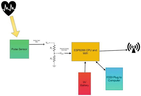
Figure 5-4. Block Diagram of IOTPulse

Figure 5-5. IOTPulse in Case
Building the IOTPulse
The parts list is shown in Table 5-2, followed by the wiring list. The parts for the IOTPulse device are readily available and only the voltage divider will require any soldering.
Table 5-2. Parts List
Part Number | Count | Description | Approximate Cost per Board | Source |
|---|---|---|---|---|
ESP8266 Huzzah Board | 1 | CPU / WiFi board | $10 | |
Pulse Sensor Amped | 1 | I2C Light Sensor | $25 | |
FTDI Cable | 1 | Cable for programming the ESP8266 from PC/Mac | $11 | http://www.switchdoc.com/inexpensive-ftdi-cable-for-arduino-esp8266-includes-usb-cable/ |
26K Ohm Resistor | 1 | 1/4 watt | $17 for a large mix of resistors (Joe Knows Electronics) | |
18K Ohm Resistor | 1 | 1/4 watt | $17 for a large mix of resistors (Joe Knows Electronics) |
Plugging the FTDI Cable into the ESP8266
An FTDI cable is plugged into the end of the Adafruit Huzzah ESP8266. Make sure you align the GND pin on the FTDI Cable with the GND pin on the ESP8266 breakout board as shown in Figure 5-6.

Figure 5-6. FTDI Cable Plugged into the Huzzah Board. Note GND Connection
Table 5-3 contains the wiring list for the IOTPulse project.
Table 5-3. IOTPulse Wiring List
From | To | Description | |
|---|---|---|---|
ESP8266/GND | PulseSensor / GND (Black Wire) | Ground for Pulse Sensor | |
ESP8266/3V | PulseSensor / 3.3V (Red Wire) | 3.3V Power for Pulse Sensor | |
PulseSensor/Output (Purple Wire) | 26K / Port A | Top of the Resistor Divider | |
26K/Port B | 18K / Port A | Middle of the Resistor Divider | |
18K/Port A | ESP8266 / GND | Ground for bottom of Resistor Divider | |
26K/Port B | ESP8266 / A0 | A0 - Analog to Digital Converter input on ESP8266 |
3D Printing Files for the IOT Case
Finding a case for a custom project can always be a problem. All of the projects in the chapters have suggested using 3D Printing to build cases that fit the project, and the IOTPulse project is no different. The most interesting part of this case is the way we designed a bevel that goes around the base so the top case will snap onto the bottom case (Figure 5-7).

Figure 5-7. IOT Case
We have introduced openSCAD , a free code-based 3D Modeler in previous chapters. There are hundreds of example models on Thingverse.com and the openSCAD web site to choose from and to learn from. Listing 5-1 contains the code that builds the case shown in Figure 5-7.
Listing 5-1. openSCAD code for the IOT Case
//// IOTPulse Case//// SwitchDoc Labs// August 2015//include <RoundedRect.scad>module rcube(size=[30, 20, 10], radius=[3, 2, 1], center=true)hull() {translate( center ? [0,0,0] : size/2 ) {cube(size-2*radius+[2*radius[0],0,0],center=true);cube(size-2*radius+[0,2*radius[1],0],center=true);cube(size-2*radius+[0,0,2*radius[2]],center=true);for(x = [-0.5,0.5], y = [-0.5,0.5], z = [-0.5,0.5])translate([x * ( size[0] - 2*radius[0]),y * ( size[1] - 2*radius[1]),z * ( size[2] - 2*radius[2])])scale([radius[0], radius[1], radius[2]])// sphere(1.0,$fn=4*4);sphere(1.0,$fn=6*6);}}module IOTPulseTopCase(){difference(){//cube([82,62,25]);rcube(size=[82,62,30],radius=[5,5,5],center=false);#translate([2,2,2])cube([78,58,25]);#translate([-10,-10,25])cube( [100,100,50]);// hole for pulse meter 18mmtranslate([-5,62/2,12.5])#rotate([0,90,0])cylinder(h=10,r=10,10);// hole for seeing light#translate([82-20,10,-2])cylinder(h=10,r=5,10);// hole for seeing wifi light#translate([82-43,10,-2])cylinder(h=10,r=5,10);}}union(){cube([78,58,4]);translate([-2,-2,0])cube([82,62,2]);// Mount for Batterytranslate([40-2,2,0])cube([40-2,1.35,20]);translate([40-2,26.10+3.3,0])cube([40-2,1.5,20]);// lips for batterytranslate([79-2,3,0])cube([1,28,6]);// plyons for ESP8266translate([70-1.0,35,0])cylinder(h=10,r1=2.2, r2=1.35/2, $fn=100);translate([70-1.0,56,0])cylinder(h=10,r1=2.2, r2=1.35/2, $fn=100);translate([70-34,35,0])cylinder(h=10,r1=2.2, r2=1.35/2, $fn=100);translate([70-34,56,0])cylinder(h=10,r1=2.2, r2=1.35/2, $fn=100);// plyons for resistors for divider// gap of 2.3mmtranslate([15,35,2])cube([1,5,5]);translate([15+3,35,2])cube([1,5,5]);translate([15,45,2])cube([1,5,5]);translate([15+3,45,2])cube([1,5,5]);// top casetranslate([0,70,0])IOTPulseTopCase();}
The code for the IOTPulse case is broken into two main sections. The main program builds the lower part of the case while the top of the case is located in the function IOTPulseTopCase(). When building models with openSCAD, it is a good idea to break different parts into functions even if you are only calling them once. It simplifies the code. Now, let us look at the software for IOTPulse.
Software Needed
For you to program the IOT Pulse board you will need a Mac or PC to program the ESP8266 via the Arduino IDE. See Chapter 2 for how to set up the Arduino IDE with the ESP8266 libraries.
The IOTPulse Code
There are three files that are part of the build for the IOTPulse software. The IOTPulse.ino is the main Arduino IDE file (in the C language), and the other two files (Interrupt.h and AllSerialHandling.h) are included in the main file. While the code is fairly straightforward, comments need to be made for each module.
IOTPulse.ino
IOTPulse.ino is the main program for IOTPulse (Listing 5-2). It consists of two major functions, setup() and loop() . The setup() function initializes the ESP8266 WiFi code, reads an IP address using DCHP from the local wireless access point, and initializes variables for containing micros(), which is a function returning the number of microseconds since the reboot of the ESP8266 micros() is a timekeeping function. Note that the ESP8266 does not have a real-time clock on board and really doesn’t know what time it is. It only knows how long it has been running. If you wish to set the time of day in the ESP8266, please check out the NTP protocol in this Instructable[ http://www.instructables.com/id/Internet-time-syncronized-clock-for-Arduino/ ].
In the IOTPulse project, we really don’t care what time it is. When we send a sample to the Bluemix IOT Platform, our friend IBM will timestamp the reception of the data. If we cared about our time, we could build an NTP receiver and synchronize it to network time at a specific NTP server. We are much more interested in intervals of time (specifically 2 milliseconds and 10 seconds intervals) rather than absolute time.
The loop() function contains the code for ongoing operation of the IOTPulse data-gathering operation. We basically do four things in the loop() function:
We check the value of QS. If QS is true, then the software in Interrupt.h has found a BPM (Beats Per Minute) and IBI (Interval Between beats) value for the current pulse rate for our PulseSensor connected to your ear.
Next, if 10 seconds have elapsed (10,000,000 microseconds), we send the current value of BPM and IBI up to the IBM Bluemix IOT cloud. We then reset the time to wait for the next 10-second interval, which is stored in the oldIOTTime variable. The actual time for the next interval is oldIOTTime + 10 seconds (10,000,000 microseconds) .
If 2 milliseconds have elapsed since oldPulseTime variable (initialized in loop()), we call the timerCallback() function defined in Interrupt.h. We then reset the oldPulseTime variable and wait for another 2ms.
Note at the end of the loop() function, there is a yield() function. This MUST be called periodically for the ESP8266 software to continue running the WiFi interface and other housekeeping functions. Remember, unlike a regular Arduino, there is a great deal going on in the background to keep this chip running and connected to the network.
One limitation of the current ESP8266 software is that you can’t use the timers [ http://www.switchdoc.com/2015/10/iot-esp8266-timer-tutorial-arduino-ide/ ] to generate interrupts without causing the WiFi to fail and stop connecting to the local WiFI access point and the Internet.
This makes it very difficult to generate an interrupt to the computer every 2ms as is called for by the PulseSensor. You could generate an interrupt every 2ms by using an external hardware timer and then connecting the output of the hardware timer to one of the GPIO pins on the ESP8266, which can all be programmed to generate an interrupt to the CPU.
To solve this issue, we use a scheduling technique that is more CPU intensive (read uses more power) than the interrupt scheme. We check the time periodically and run the PulseSensor software every 2ms and also connect to the IBM Bluemix every 10 seconds.
The biggest disadvantage of this is that we cannot “sleep” the processor very easily. We are looking for an alternative architecture for this problem and are watching the ESP8266 development web sites for solutions.
However, with the exception of power consumption, the current solution works well.
Listing 5-2. IOTPulse.ino
/*SwitchDoc Labs Code for IOT PulseConnects Pulse detector to the IBM Bluemix IoT using a ESP8266 processorbased on pulsecounting code from www.pulsesensor.comNovember 2015---------------------- Notes ---------------------- ----------------------This code:1) Blinks an LED to User's Live Heartbeat PIN 02) Determines BPM3) Sends information to the IBM Bluemix IOT*/extern "C" {#include "user_interface.h"}#include <ESP8266WiFi.h>#include <PubSubClient.h> // https://github.com/knolleary/pubsubclient/releases/tag/v2.3//----------------------------------------------------------------------//Local WiFi Variablesconst char* ssid = "yourssid";const char* password = "yourpassword";#define IOTPULSEVERSION 004// IBM BlueMix IOT Foundation Data#define ORG "XXXXX"#define DEVICE_TYPE "IOTPulse-01"#define DEVICE_ID "1"#define TOKEN "YYYYYYYYY"// setup for IOT IBMchar server[] = ORG ".messaging.internetofthings.ibmcloud.com";char topic[] = "iot-2/evt/status/fmt/json";char authMethod[] = "use-token-auth";char token[] = TOKEN;char clientId[] = "d:" ORG ":" DEVICE_TYPE ":" DEVICE_ID;//----------------------------------------------------------------------// Variablesint pulsePin = A0; // Pulse Sensor purple wire connected to analog pin 0int blinkPin = 0; // pin to blink led at each beatint fadePin = 5; // pin to do fancy classy fading blink at each beatint fadeRate = 0; // used to fade LED on with PWM on fadePin// Volatile Variables, used in the interrupt service routine!volatile int BPM; // int that holds raw Analog in 0. updated every 2mSvolatile int Signal; // holds the incoming raw datavolatile int IBI = 600; // int that holds the time interval between beats! Must be seeded!volatile boolean Pulse = false; // "True" when User's live heartbeat is detected. "False" when not a "live beat".volatile boolean QS = false; // becomes true when Arduoino finds a beat.// Regards Serial OutPut -- Set This Up to your needsstatic boolean serialData = true; // Set to 'false' by Default. Re-set to 'true' to see Arduino Serial Monitor data#include "AllSerialHandling.h"#include "Interrupt.h"void callback(char* topic, byte* payload, unsigned int length) {Serial.println("callback invoked from IOT BlueMix");}WiFiClient wifiClient;PubSubClient client(server, 1883, callback, wifiClient);unsigned long oldPulseTime;unsigned long oldIOTTime;void setup() {pinMode(blinkPin, OUTPUT); // pin that will blink to your heartbeat!Serial.begin(115200); // we agree to talk fast!Serial.println("----------------");Serial.println("IOTPulse IBM Bluemix IOT");Serial.println("----------------");Serial.print("Connecting to ");Serial.print(ssid);// NOTE below: Newer versions of the ESP8266 Libraries may require the following statement// instead of the other statement. WiFi.SSID() has changed definitions in new versions// if (strcmp (WiFi.SSID().c_str(), ssid) != 0) {if (strcmp (WiFi.SSID(), ssid) != 0) {WiFi.begin(ssid, password);}while (WiFi.status() != WL_CONNECTED) {delay(500);Serial.print(".");}Serial.println("");Serial.print("Local WiFi connected, IP address: ");Serial.println(WiFi.localIP());// interruptSetup(); // sets up to read Pulse Sensor signal every 2mS// Note: Interrupts based on os_timer seems to break the ESP8266 WiFi. Moving to micros() polling methodologyoldPulseTime = micros();oldIOTTime = micros();}int sampleCount = 0;int beatCount = 0;int beatValue = 0;unsigned long newPulseDeltaTime;unsigned long newIOTDeltaTime;// Where the Magic Happensvoid loop() {//serialOutput() ;if (QS == true) { // A Heartbeat Was Found// BPM and IBI have been Determined// Quantified Self "QS" true when arduino finds a heartbeatdigitalWrite(blinkPin, LOW); // Blink LED, we got a beat.beatCount++;serialOutputWhenBeatHappens(); // A Beat Happened, Output that to serial.QS = false; // reset the Quantified Self flag for next time}newPulseDeltaTime = micros() - oldPulseTime; // doing this handles the 71 second rollover because of unsighned arithmeticnewIOTDeltaTime = micros() - oldIOTTime; // doing this handles the 71 second rollover because of unsighned arithmetic// do this every ten secondsif (newIOTDeltaTime > 10000000) // check for 10sec work to be done{Serial.print("IOT Delta time =");Serial.println(newIOTDeltaTime);sampleCount++;// Sending payload: {"d":{"IOTPulse":"IP1","VER":2"SC":0,"BPM":235,"IBI":252}}String payload = "{"d":{"IOTPulse":"IP1",";payload += ""VER":";payload += IOTPULSEVERSION;payload += ","SC":";payload += sampleCount;payload += ","BPM":";payload += BPM;payload += ","IBI":";payload += IBI;payload += ","BC":";payload += beatCount;payload += "}}";if (!!!client.connected()) {Serial.print("Reconnecting client to ");Serial.println(server);while (!!!client.connect(clientId, authMethod, token)) {Serial.print(".");delay(500);}Serial.println();}Serial.print("Sending IOTPulse payload: ");Serial.println(payload);if (client.publish(topic, (char*) payload.c_str())) {Serial.println("BlueMix IOT Publish ok");} else {Serial.println("BlueMix IOT Publish failed");}oldIOTTime = micros();// restart the pulse counterrestartPulse();}//Serial.print("micros()=");//Serial.println(micros());if (newPulseDeltaTime > 2000) // check for 2ms work to be done{//Serial.print("Pulse Delta time =");//Serial.println(newPulseDeltaTime);// do the work for pulse calculationtimerCallback(NULL);oldPulseTime = micros();}yield(); // take a break}
AllserialHandling.h (Listing 5-3) contains the serial output debugging routines that are useful when modifying the code.
Listing 5-3. AllSerialHandling.h
/////////////////// All Serial Handling Code,///////// It's Changeable with the 'serialVisual' variable///////// Set it to 'true' or 'false' when it's declared at start of code./////////void sendDataToSerial(char symbol, int data );void serialOutput() { // Decide How To Output Serial.sendDataToSerial('S', Signal); // goes to sendDataToSerial function}// Decides How To OutPut BPM and IBI Datavoid serialOutputWhenBeatHappens() {if (serialData == true) { // Code to Make the Serial Monitor Visualizer WorkSerial.print("*** Heart-Beat Happened *** "); //ASCII Art MadnessSerial.print("BPM: ");Serial.print(BPM);Serial.print(" IBI: ");Serial.print(IBI);Serial.println(" ");}}// Sends Data to Pulse Sensor Processing App, Native Mac App, or Third-party Serial Readers.void sendDataToSerial(char symbol, int data ) {Serial.print(symbol);Serial.println(data);}
Interrupt.h (Listing 5-4) is called this because the original PulseSensor software used an Arduino timer to generate a 2ms interrupt. As is explained above, the ESP8266 is not currently capable of doing the same thing while maintaining a functional WiFi interface. The function timerCallback() in Interrupt.h is now called at a scheduled time by the loop() function in the IOTPulse.ino file.
Basically, timerCallback() acts as a detector and averaging filter that detects the upswing on the PulseSensor output and then builds a set of times for IBI (Interval Between beats) and provides an average. It adjusts to the recorded levels coming from the PulseSensor because the actual level is not as important as the time interval between adjusted pulses from the PulseSensor. The software acts as a peak and trough detector with an average system that removes high-frequency noise.
Listing 5-4. Interrupt.h
volatile int rate[10]; // array to hold last ten IBI valuesvolatile unsigned long sampleCounter = 0; // used to determine pulse timingvolatile unsigned long lastBeatTime = 0; // used to find IBIvolatile int P = 680; // used to find peak in pulse wave, seeded 512volatile int T = 680; // used to find trough in pulse wave, seeded 512volatile int thresh = 700; // used to find instant moment of heart beat, seeded 525volatile int amp = 100; // used to hold amplitude of pulse waveform, seededvolatile boolean firstBeat = true; // used to seed rate array so we startup with reasonable BPMvolatile boolean secondBeat = false; // used to seed rate array so we startup with reasonable BPMvoid restartPulse(){sampleCounter = 0; // used to determine pulse timinglastBeatTime = 0; // used to find IBIP = 680; // used to find peak in pulse wave, seeded 512T = 680; // used to find trough in pulse wave, seeded 512thresh = 700; // used to find instant moment of heart beat, seeded 525amp = 100; // used to hold amplitude of pulse waveform, seededfirstBeat = true; // used to seed rate array so we startup with reasonable BPMsecondBeat = false;}void timerCallback(void *pArg);// Timer makes sure that we take a reading every 2 milisecondsvoid timerCallback(void *pArg) { // triggered on interrupts//cli(); // disable interrupts while we do thisSignal = analogRead(pulsePin); // read the Pulse Sensor//Serial.print("Signal-A0-:");//Serial.println(Signal);sampleCounter += 2; // keep track of the time in mS with this variableint N = sampleCounter - lastBeatTime; // monitor the time since the last beat to avoid noise// find the peak and trough of the pulse waveif (Signal < thresh && N > (IBI / 5) * 3) { // avoid dichrotic noise by waiting 3/5 of last IBIif (Signal < T) { // T is the troughT = Signal; // keep track of lowest point in pulse wave}}if (Signal > thresh && Signal > P) { // thresh condition helps avoid noiseP = Signal; // P is the peak} // keep track of highest point in pulse wave// NOW IT'S TIME TO LOOK FOR THE HEART BEAT// signal surges up in value every time there is a pulseif (N > 250) { // avoid high frequency noiseif ( (Signal > thresh) && (Pulse == false) && (N > (IBI / 5) * 3) ) {Pulse = true; // set the Pulse flag when we think there is a pulsedigitalWrite(blinkPin, LOW); // turn on LEDIBI = sampleCounter - lastBeatTime; // measure time between beats in mSlastBeatTime = sampleCounter; // keep track of time for next pulseif (secondBeat) { // if this is the second beat, if secondBeat == TRUEsecondBeat = false; // clear secondBeat flagfor (int i = 0; i <= 9; i++) { // seed the running total to get a realisitic BPM at startuprate[i] = IBI;}}if (firstBeat) { // if it's the first time we found a beat, if firstBeat == TRUEfirstBeat = false; // clear firstBeat flagsecondBeat = true; // set the second beat flag//sei(); // enable interrupts againreturn; // IBI value is unreliable so discard it}// keep a running total of the last 10 IBI valuesword runningTotal = 0; // clear the runningTotal variablefor (int i = 0; i <= 8; i++) { // shift data in the rate arrayrate[i] = rate[i + 1]; // and drop the oldest IBI valuerunningTotal += rate[i]; // add up the 9 oldest IBI values}rate[9] = IBI; // add the latest IBI to the rate arrayrunningTotal += rate[9]; // add the latest IBI to runningTotalrunningTotal /= 10; // average the last 10 IBI valuesBPM = 60000 / runningTotal; // how many beats can fit into a minute? that's BPM!// reduce to 83% based on comparisonBPM= (BPM * 83)/100;QS = true; // set Quantified Self flag// QS FLAG IS NOT CLEARED INSIDE THIS ISR}}if (Signal < thresh && Pulse == true) { // when the values are going down, the beat is overdigitalWrite(blinkPin, HIGH); // turn off pin 13 LEDPulse = false; // reset the Pulse flag so we can do it againamp = P - T; // get amplitude of the pulse wavethresh = amp / 2 + T; // set thresh at 50% of the amplitudeP = thresh; // reset these for next timeT = thresh;}if (N > 2500) { // if 2.5 seconds go by without a beatthresh = 512; // set thresh defaultP = 512; // set P defaultT = 512; // set T defaultlastBeatTime = sampleCounter; // bring the lastBeatTime up to datefirstBeat = true; // set these to avoid noisesecondBeat = false; // when we get the heartbeat back}//sei(); // enable interrupts when youre done!}// end isr
Reviewing the Arduino IDE Serial Monitor Results
Listing 5-5 shows the output from the Serial Monitor on the Arduino IDE as you run the software. Note that this code was run after joining the IBM Bluemix IOT as shown later in this chapter. If you haven’t joined the Bluemix IOT yet, then you will see an “authentication failed” error every time that the IOTPulse software tries to contact Bluemix.
Listing 5-5. Serial Monitor Output
IOTPulse IBM Bluemix IOT----------------Connecting to gracie........Local WiFi connected, IP address: 192.168.1.117*** Heart-Beat Happened *** BPM: 92 IBI: 534*** Heart-Beat Happened *** BPM: 91 IBI: 630*** Heart-Beat Happened *** BPM: 92 IBI: 468*** Heart-Beat Happened *** BPM: 91 IBI: 590*** Heart-Beat Happened *** BPM: 92 IBI: 516*** Heart-Beat Happened *** BPM: 91 IBI: 548*** Heart-Beat Happened *** BPM: 91 IBI: 530*** Heart-Beat Happened *** BPM: 91 IBI: 556*** Heart-Beat Happened *** BPM: 91 IBI: 540*** Heart-Beat Happened *** BPM: 91 IBI: 530*** Heart-Beat Happened *** BPM: 90 IBI: 586*** Heart-Beat Happened *** BPM: 92 IBI: 538*** Heart-Beat Happened *** BPM: 90 IBI: 540*** Heart-Beat Happened *** BPM: 91 IBI: 564IOT Delta time =10000002Reconnecting client to 4183lj.messaging.internetofthings.ibmcloud.com.Sending IOTPulse payload: {"d":{"IOTPulse":"IP1","VER":4,"SC":1,"BPM":91,"IBI":564,"BC":14}}BlueMix IOT Publish ok*** Heart-Beat Happened *** BPM: 87 IBI: 564*** Heart-Beat Happened *** BPM: 87 IBI: 574*** Heart-Beat Happened *** BPM: 87 IBI: 546*** Heart-Beat Happened *** BPM: 87 IBI: 566*** Heart-Beat Happened *** BPM: 87 IBI: 572*** Heart-Beat Happened *** BPM: 87 IBI: 584*** Heart-Beat Happened *** BPM: 87 IBI: 570*** Heart-Beat Happened *** BPM: 87 IBI: 582*** Heart-Beat Happened *** BPM: 87 IBI: 590*** Heart-Beat Happened *** BPM: 86 IBI: 582*** Heart-Beat Happened *** BPM: 86 IBI: 572*** Heart-Beat Happened *** BPM: 85 IBI: 610*** Heart-Beat Happened *** BPM: 85 IBI: 572IOT Delta time =10000009Reconnecting client to 4183lj.messaging.internetofthings.ibmcloud.com.Sending IOTPulse payload: {"d":{"IOTPulse":"IP1","VER":4,"SC":2,"BPM":85,"IBI":572,"BC":27}}BlueMix IOT Publish ok*** Heart-Beat Happened *** BPM: 108 IBI: 456*** Heart-Beat Happened *** BPM: 106 IBI: 562*** Heart-Beat Happened *** BPM: 103 IBI: 568*** Heart-Beat Happened *** BPM: 101 IBI: 574*** Heart-Beat Happened *** BPM: 98 IBI: 576*** Heart-Beat Happened *** BPM: 96 IBI: 582
Figure 5-8 shows the completed IOTPulse device in the case. Note the holes on the top to view the LEDs on the ESP8266 board. Figure 5-9 shows the pulse sensor clipped on an ear. Notice the green LED used for sensing the pulse rate in the ear.
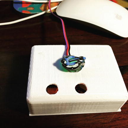
Figure 5-8. IOTPulse in Case
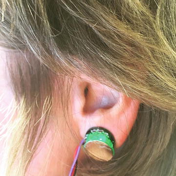
Figure 5-9. IOTPulse Sensor on Ear
Joining IBM Bluemix and the IoT Foundation
The IBM BlueMix and the IoT Foundation are the two key IOT cloud services we will be using to connect up the IOTPulse device to the cloud. The tasks that need to be done to connect up mostly have to do with setting up user accounts and putting billing information into the system. Note that we are using the free levels of the Bluemix system, but IBM still requires billing information. The most important technical information we will gather is how to authenticate our IOT device to the IBM cloud. Figure 5-10 describes the overall architecture of the Bluemix/IoT Foundation cloud application.

Figure 5-10. IBM Bluemix Block Diagram
The IoT Foundation is the IBM Bluemix service that we will need to hook up the ESP8266 to the Bluemix cloud service. You will need to create an IBM ID account. You can do so on the Bluemix home page shown in Figure 5-11.

Figure 5-11. IBM Bluemix First Page
The steps to join IBM Bluemix are the following:
Create an IBM ID account here;
Validate your account through the IBM sent e-mail;
Go to the IBM Bluemix site and click Log In;
Sign in on the login page;
Go to the Bluemix Dashboard;
Click USE SERVICES OR APIS;
Add the Internet of Things Foundation Service (It is WAY down at the bottom of the list on the web page).
You should then have a screen similar to the one in Figure 5-12, with the exception of the “IoT Real-Time Insights” panel, which will be added to your Bluemix account later in this chapter.

Figure 5-12. Bluemix Dashboard
Sending your Data to Bluemix
First of all, what do we send up to Bluemix from the ESP8266? It turns out the data protocols are pretty straightforward There are two major protocols that require descriptions.
MQTT and JSON.
MQTT
MQTT is a publish-subscribe-based "light weight" messaging protocol for use on top of the TCP/IP protocol, such as the WiFi packets that we are using in this project. It is designed for connections with remote locations where a "small code footprint" is required or the network bandwidth is limited. Both of these conditions are met with an ESP8266 IOT design, so it makes sense to use. There is also an excellent library available for MQTT for the Arduino IDE [ https://github.com/knolleary/pubsubclient ]. The publish-subscribe messaging pattern requires a message broker. The broker is responsible for distributing messages to interested clients based on the topic of a message (Figure 5-13) .

Figure 5-13. MQTT Publish-Subscribe Protocol
Publish-subscribe is a pattern where senders of messages, called publishers (in this case our ESP8266 is the publisher), don't program the messages to be sent directly to subscribers, but instead characterize message payloads into classes without the specific knowledge of which subscribers the messages are sent to. Similarly, subscribers (the IBM Bluemix IOT in this case) will only receive messages that are of interest without specific knowledge of which publishers there are. The IBM Bluemix operates as the broker in this system and routes the published data to the appropriate subscribers inside of Bluemix.
JSON Data Payload
JSON is an open standard format that uses human-readable text to transmit data objects consisting of attribute–value pairs. It is the primary data format used for asynchronous browser/server communication, largely replacing XML. XML is a "heavier" protocol that is also hierarchical in nature, but with a great deal more redundancy that JSON. Yes, there are class wars going on for people that advocate JSON over XML, but in today’s world of higher speed communication, it rarely matters. You can make the argument that the higher data density of JSON is a better choice for IOT applications.
Here is an example of the data packet we are using in the ESP8266 Bluemix code in JSON for the LightSwarm data payload:
{"d":
      {
         "LightSwarm IOT":"LS1",
         "sampleCount":2118,
         "lightValue":383
      }
}
Authentication
We need to have a secure method of authenticating that our ESP8266 device is allowed to put data into the right slots inside the IBM Bluemix. This is done in our case by exchanging a cryptographic token that was generated by Bluemix and included in our ESP8266 code.
To do this we need to go back to the Bluemix account that you set up in the previous posting and complete the following steps:
Click the Internet of Things Foundation icon on the Bluemix dashboard.
Next, click the Launch dashboard button under “Connect your devices” (Figure 5-14).
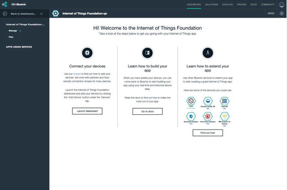
Figure 5-14. Connect your Devices to Bluemix
Go to the Devices Tab and “Add Device” down at the bottom of the page.
Click “Create Device Type,” and the screen in Figure 5-15 appears .

Figure 5-15. Create Bluemix Device Type
We would suggest you use IOTPulse-01 for the name of the device type.
Move through the rest of the steps. There are many configuration options that nearly all can be left blank in our current application. You are required to have a device type and a device ID.
When the device has been created, you’ll see the Device Credentials page. Be sure to save those details, as they are used to authenticate your ESP8266 Arduino IDE sketch in in the next step (we have not found any way of recovering these credentials from the Bluemix system). Obviously, don't use the credentials in Figure 5-16. They will not work. You need to create your own.

Figure 5-16. Bluemix Credential Screen
Displaying Real-Time Data on the IBM Bluemix IOT Platform
In order to get a display going in the Bluemix platform, we need to connect our device to the IoT Real-Time Insights service on Bluemix. The following sections discuss this.
Adding Real-Time Insights
Step 1: Add the IoT Real-Time Insights service to your Bluemix dashboard. Open the Bluemix dashboard (the first dashboard after login) and click “USE SERVICES OR APIS” and add the IoT Real-time Insights as a service. It is way down at the bottom of the page. You will then see the screen in Figure 5-17.
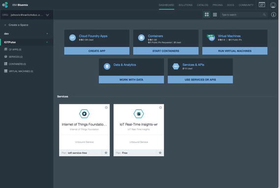
Figure 5-17. IoT Real-Time Insights
Step 2: Connect our device to the IoT Real-Time Insights Page by generating an API key and then generating a data source. Click the IoT Real-Time Insights block shown in Figure 5-16.
Step 3: Generate the API keys for using the Data Source and create API keys to connect the two services (IoT Foundation and IoT Real-Time Display):
From the Bluemix dashboard, click the Internet of Things tile.
Click Launch dashboard to open the Internet of Things Foundation dashboard.
Navigate to Access > API Keys.
Click Generate API Key.
Make a note of the API Key, Authentication Token, and the Organization ID that is displayed at the top of the IoT Foundation dashboard. You use this information in IoT Real-Time Insights to connect the services. These keys will remain displayed in the data source.
Adding the Data Source
Adding the data source (our IOTPulse device) consists of the following (Figure 5-18):
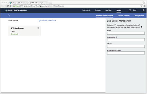
Figure 5-18. Adding the Data Source
Go to Devices > Manage Schemas and click Add new message schema.
Enter a name for the message schema: for example, IOTMessageSchema.
Click Link new data source and select the data source and device type that corresponds to your IoT Foundation instance and device. Event types for your device are here.
Add one or more data points that you want to include in the device dashboards (sampleCount and lightValue in our example).
The available data points are defined in the JSON payload of the messages that are sent by a device.
Click Select from connected device.
In the Add data points dialog, select one or more data points to add, and then click OK.
The selected data points are added with the description set to the name of the data point.
Then click the green arrow (on the left side of the screen) to save the information and create the data source .
Once all of the configuration data is in place and the authentication information is in place in the IOTPulse program, data should start to flow as shown in Figure 5-19.

Figure 5-19. IOT Data Starts to Flow
Now we add the displays to visualize our data.
Adding the Dashboard to the IoT Real-Time Display
From the screen in Figure 5-20, click Launch IoT Real-Time Insights Dashboard in the lower right-hand column.

Figure 5-20. IoT Real-Time Insights
Click dashboard and browse dashboards. Add a new dashboard. Then do the following:
Add new component;
Select chart;
Add line to the chart;
Select your device and then select lightValue as the parameter;
Click the green arrow.
Figure 5-21 shows the IBM BlueMix screen for laying out your dashboard interface.
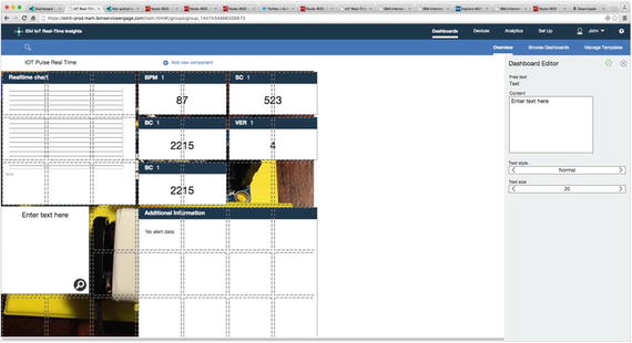
Figure 5-21. Building your IoT Real-TimeDashboard
If your ESP8266 is running and sending data up to the IBM Bluemix IOT, then you will see the values start to populate the graph, as shown in Figure 5-22.

Figure 5-22. Bluemix IoT Real-Time Dashboard Operational
Advanced Topics
The IBM cloud offerings have literally hundreds of options and possibilities for bringing your IOT data to the cloud. Below we show a few of these “apps” available on the Bluemix system. We will show how to graph your historical IOT data and introduce a complex, but very powerful, programming system, Node-RED.
Historical Data
Non-real-time historical data can also be viewed in Bluemix (Figure 5-23). This requires you to build an app (not as complex as you might think) and then deploy the app. A good tutorial for this is located on the IBM Bluemix web site [ https://www.ng.bluemix.net/docs/starters/install_cli.html ]. It does require you to install a command-line interface for Cloud Foundry on your computer.
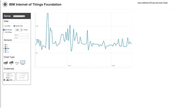
Figure 5-23. Historical IOTPulse Data
One thing this historical data graph of our pulse rate does show is that the data from IOTPulse could be improved by more filtering. The average of the heart rate looks good, but the jumps up and down look like noise, especially earlier in the graph.
Node-RED Applications
Node-RED is a graphical tool for wiring together devices, external APIs, and online services. You use a browser-based flow editor that makes it simple to wire together flows from an extensive library And it is easy to add your own nodes.
Node-RED is fully supported by IBM Bluemix. It is primarily an event-based software generation system. If an event happens (such as IOTPulse sending data), you can take that data and process it in various ways, send it to other applications, and store it in databases. Other inputs can cause displays to be updated, queries to be sent to databases, and many other events .
We built a small Node-RED application for IOTPulse shown in Figure 5-24.

Figure 5-24. Node-RED Application Flow for IOTPulse
Watson Applications
One of the more exciting class of applications that can be built in Bluemix are those utilizing the IBM Watson software. All of the Watson services on the Bluemix platform are accessed via HTTP transfers known as REST services. REST stands for Representation State Transfer and is a common way of accessing web-based services.
Watson supports a number of very sophisticated services all available to your device and applications in Bluemix:
Speech to Text
Text to Speech
Language Translation
Support for User Dialogs
Determining the “Tone” for Text
Visual Recognition
Image Analysis - Objects, People, and Text
Conclusion
The future of the IOT is data: how to gather it, how to transmit it, how to analyze and display it, and how to act on it. The IOTPulse project shows how to gather data and how to send it up to a cloud computing system for analysis and actions.
With a proper sensor, the IOTPulse project could be a commercial product. The sensor and analysis of the heart rate are definitely not medical grade, but still illustrates the principles of the IOT device and the device relationship with the IOT cloud.