The entire book up until this point was spent talking about requirements as purely shall statements. This concept of requirements was the foundation of the waterfall development methodology, starting with hardware and then translated to software. However, other types of requirements are referred to such as user stories, use cases, and modeling. Now you will be exposed to these types of requirements and how you can use them to supplement or replace shall statements. This and the next two chapters will discuss each topic so that you will be able to create them as needed, and why.
One of the significant drawbacks of the waterfall method for software development is that once you capture requirements, you freeze that baseline at that point. Given that, on average, requirements for a project change from 1 to 4 percent per month, the scope of the project may change significantly by the time it is delivered. The waterfall method is not agile enough in many cases. Thus, newer approaches were needed. With rapid application development (RAD), use cases came into being. With the advent of extreme programming and other agile methodologies, user stories came into being.
In addition, modeling techniques become important for programs to represent information to aid in the development of the hardware and software. This chapter will briefly introduce each subject and then examine the advantages and disadvantages of each.
One additional point to make about a collection of shall statement: it is not the easiest document for users and stakeholders to understand and then review and comment on. As a stakeholder whose primary purpose is to use a particular system to do their job, they are not necessarily well versed in requirements. If they are exposed to hundreds or even thousands of shall statement in a long list, with little paragraph descriptions to give context to them, they may not be able to get a comprehensive picture of the system. Thus, having another way to either replace shall statements or supplement them will obviously help these stakeholders comprehend the proposed system.
This chapter covers a variety of approaches and tools that can supplement or replace the traditional requirements techniques discussed thus far.
User stories and use cases are exceptional cases because they are uniquely valuable for capturing certain kinds of requirements that traditional shall statements do not handle as well. They also are general approaches that are often especially useful with agile development. Therefore, they are introduced in this chapter but discussed in more depth in two dedicated chapters that follow this one.
Modeling provides tools that are particularly useful for supplementing technical requirements, but only some modeling techniques work for ordinary user and stakeholder requirements. In this chapter, I will focus on a couple of techniques that are more generally useful for users and stakeholders (such as swim lanes) and then introduce techniques that have more specialized application for technical users. There are additional resources you will find useful if you have a need to write more specialized requirements, and I’ll note those resources and include them in the “References” section.
There are some additional tools that can serve as useful supplements in the requirements gathering process, and I will cover those briefly in the final section.
User Stories and Use Cases
If there are alternatives to writing shall statements, why was so much time spent focusing on them? Excellent question. First, as you will see in the “Supplement to Requirements” section in this chapter, shall statements are not going away. Second, understanding all the aspects of requirements is an excellent foundation to have to write user stories and use cases. Without that foundation, it would take you considerably longer to craft user stories and use cases, as you will see in the next two chapters, in which we look at these topics in more depth. In addition, when you see the advantages and disadvantages of the various alternatives, you will have a better basis for comparison.
User Stories
A user story follows this type of template:
12-1 “As a <role>, I want <function/feature> so that <benefit>.”
Where the role is the type of user, the function or feature is what the user does or uses, and the benefit is why the user would want to use this function or feature. For example, a user story could be as follows:
12-2 As a cell phone user, I want to retain a list of selective phone numbers that I have received so that I can choose which numbers I want to reuse later.
Notice how easy it is to read? That is a significant benefit for users and stakeholders to understand them. This is a big advantage in that users can understand these even better than shall statements.
User stories work well with the agile methodology. The user story and subordinate acceptance criteria (which will be talked about in the next chapter) can be refined as the user story approaches the sprint in which the development team plans to work on it. This helps to negate the effect of requirements scope creep, unlike in the waterfall approach where you must create all the requirements up front.
Does this mean that user stories are the pinnacle of requirements technology? While it goes a long way to fix requirements problems, it still has some limitations. Because the development team intends to accomplish each user story in an individual sprint, some areas that you need to define do not fit well. Nonfunctional requirements, especially performance, are much harder to capture as a user story. Remember, in the “Availability” section in Chapter 5, you saw the following requirement:
12-3/5-54 The BOSS system shall be available 99.99% of the time.
How would it look as a user story?
12-4 DRAFT As a BOSS user, I want the system to be available 99.99% of the time so that the system provides the availability I need since it is a mission-critical function.
That sounds like a reasonable user story, and on the surface, it is. However, can the development team accomplish that in one sprint? Assume the development team has six user stories it is responsible for developing in a given sprint. Does availability apply to each user story? Technically, yes. Then, how do they verify that it is accomplished? What about all the work accomplished before the sprint in question. Does the availability user story apply to them? Yes. Now you start to see the conundrum—one availability user story may not address how it should be applied to an application development. In the next chapter, you will see this discussed a bit more to suggest how you might consider it.
Use Cases
Usability.gov provides some good information on use cases (as do other sources). They say that a use case is a written description of how users will perform tasks on your system.
What elements should be included in a use case? Depending on how in depth and complex you want or need to get, use cases describe a combination of the following elements:
Title: This is an identifier or name of the use case.
Description: This is a brief description of the purpose of the use case.
Actor: This is anyone or anything (another system) that performs a behavior—who is using the system. This is not limited to one actor.
Preconditions: This is what must be true or happen before the use case runs.
Postconditions: This is what must be true or happen after the use case runs.
Triggers: This is the event that causes the use case to be initiated.
Main success scenarios (aka basic flow): This is a use case in which nothing goes wrong.
Alternative paths (aka alternative flow): These paths are a variation on the main theme. These exceptions are what happen when things go wrong at the system level or an alternate condition causes a change to the basic flow.
Table 12-1 is an example of a use case (12-5).
Table 12-1. A Use Case with Basic and Alternative Flows
Title | Dial a Phone Number |
|---|---|
Description | Use your cell phone to enter a phone number. |
Actor | Phone users. |
Preconditions | Actor has a cell phone. |
Postconditions | The phone connects to the number called. |
Triggers | A need to call someone. |
Basic Flow | 1. Turn on the cell phone. 2. Select the dial option/app. 3. Key in the number. 4. The phone rings. |
Alternative Flow | 1. Select from a list. 2. Select the dial option/app. 3. Choose the number from the list provided. 4. Tap the number desired. 5. The phone rings. |
Note
Dialing a wrong number or needing to redial the number if the phone was not answered would not be part of this use case as the goal is to dial a number. A different use case could cover the option for handling the answering of a call.
You can see that this is much more detailed than a user story and provides more data than shall statements. One significant advantage use cases have over shall statements is that the sequence of steps is addressed well.
Naturally, there are some challenges with this approach.
Use cases are not so good for system centric functions such as batch processing, data warehouses, and very computationally intensive functions. How would you represent a complex algorithm? Think of the software to control an interplanetary spacecraft, with significant mathematical calculations.
In addition, nonfunctional requirements, especially performance, are harder to capture and craft. They have no actors, and they do not have alternate flow readily apparent. Additionally, many users are not comfortable trying to understand this structure.
Real-World Note
I have primarily used use cases when the “customers” were developers, not real users or stakeholders. This is because developers are generally more technically inclined than the general-population stakeholders. They can follow the structured format and sequence of steps.
Use cases may work better for the waterfall approach, as they are prepared up front, not necessarily as just-in-time development. Of course, you can create use cases this way, but there is potential for impact to other use cases—usually referred to as the ripple effect where a change ripples through other areas. For example, if you have four use cases dealing with using people’s roles and responsibilities to determine what functions they can access, and if you change one use case, you will need to verify that one change does not affect any other use case.
You have learned to perform gap analysis during the shall statement analysis. That approach also applies here. How easy is it to ensure all aspects of every use case are captured? With shall statements, you have very detailed statements that address each point. There is much more detail in a use case, and with the overlap potential between use cases, there is the possibility of small gaps appearing adjacent to these use cases. You may be missing some alternative flows that are not obvious to you. Alternatively, they are just very miniscule use cases that are not obvious. This does not mean that you cannot find them, but it may be challenging. More time will be spent analyzing this in Chapter 14.
Supplementing Your Requirements
Supplementing requirements means that you can use user stories, use cases, or combinations of them, in conjunction with shall statements.
Because of the flow of steps in use cases, there is a benefit of preparing them. It may be you do not need to do it for everything within your system. However, it provides additional detail that a list of hundreds, or thousands, of shall statements does not provide.
User stories have the benefit of being much more understandable to users. On one project, the collection of shall statements was taking much longer than initially anticipated. The RE working with management decided to craft user stories with the users and stakeholders but add the shall statements for the development team. This worked out well, as both the stakeholders and developers received the level of detail that they needed respectively.
Replacements for Requirements
This section will address the possibility that user stories or use cases can work as a replacement for requirements. Each one of these approaches will be looked at individually. User stories are intended to act as stand-alone requirements. Seeing the success of methodologies that use them demonstrates that they do work as replacements. It is safe to conclude that user stories without shall statements can work.
Real-World Note
The most recent example I have worked with where this occurred was a small development team of three people. The team lead had worked on this project for years and had an extensive understanding of the project. The requirements were documented only with user stories, without any shall statements. The team stated that they did not require the level of detail provided by shall statements, as the user stories provided what they needed. Not only did this team perform the coding but also the testing. I have observed other teams where there were separate coders and testers, and in most of these cases, the shall statements helped support the user stories. Nevertheless, there are cases where users stories can completely replace shall statements.
Use cases also are intended to act as stand-alone requirements. Seeing the success of methodologies that use them demonstrates that they do work as replacements. Thus, it is safe to conclude that use cases without shall statements can work.
Real-World Note
I worked on a recent project that used the rapid application development methodology. Again, it worked because the development team had used use case definition without shall statements for years. I was the requirements team lead, and all of my team members had been coders before, so they knew the precise level of detail the developers needed, and they provided it. The structured use cases were provided to developers who understood what the users needed. Thus, use cases can be used instead of shall statements.
The gist of performing use cases and user stories with or without shall statements comes down to “It depends on the situation.” What is the situation, and how will you use the information? The stakeholders and their level of understand and technical sophistication will drive much of the focus, as well as what your organization is comfortable with doing. As a junior requirements engineer, you may not have a lot of say on this. In addition, seeing different approaches over your career can help lend credence to your recommendations.
Now, onto our next topic.
Modeling
Chapter 9 talked about how good requirements gathering techniques may not successfully capture all requirements. Some things don’t lend themselves to representation in natural language text, so we can look to examples of pictures that can capture things more effectively than words and mathematical precision that doesn’t translate well into words. Modeling and other graphical representation techniques are attempts to provide that precision and leverage the strengths of visual imagery .
Modeling is an approach to represent a need in a more precise manner than can be achieved by just text only. Modeling uses more structured approaches to represent information that can be a varied combination of text and graphics. Modeling can vary from relatively simple graphical representations to very complex approaches that include multiple techniques.
Why is modeling useful for requirements? The natural language used to write text is not always as precise as REs would like it. Mathematics is precise, yet humans have not found a way to translate all words into equations. Modeling is an attempt to provide that precision.
That is not to say you should not use modeling techniques or graphics. If you do, make certain what you use is appropriate for your audience. Take into consideration the level of technical expertise of your users and stakeholders. Remember, the goal is to communicate effectively with them.
Back in the ancient history of chisels and stone programming days called Hollerith cards, programmers were supposed to write flow charts to plan out programs to prevent writing bugs into the code. Being undergraduates, programmers looked for shortcuts to get the programs written quickly and easily, so they ignored that advice, to their detriment. As programs grew more sophisticated, techniques improved beyond those rudimentary flow charts they should have used.
General Modeling
You will examine approaches that might use a graphic representation that might help enhance the message of the text you have written so that users can better understand, like swim lanes.
When you do use modeling and other graphical techniques, make certain what you use is appropriate for your audience. You will examine the technical level associated with each technique in its respective section. Take into consideration the level of technical expertise of your users and stakeholders. Remember, the goal is to communicate effectively with your target audience—stakeholders who will help you gather requirements.
In some cases, if your organization uses no modeling or graphic representation techniques, you may want to consider one or more to enhance communications. The more likely situation is that your organization already uses one or more models, so you need to be aware of them so you can then learn the technique.
There is one significant drawback to modeling—users/stakeholders may be model-illiterate. By that, they do not have the technology background to understand various models. You will be exposed to the use of swim lanes as one approach that might use a graphic representation that might help enhance the message of the text you have written so that users can better understand.
However, the more technical in nature of the model, the less likely a typical nontechnical user will glean information from it. Consider those when you evaluate ways to represent requirements.
If models do not effectively support the users, why would REs employ them? The primary purpose is to enhance the understanding of the requirements for the designers and developers and even requirements engineers. There are two subsections in the modeling section specifically targeted for user/stakeholders, “Models for Ordinary Requirements” and “Tools That Can Aid Requirements Gathering.” Does that mean they can be used only for that audience? Of course not. It just means that these tools are much better when your audience is not so technically focused. The specialized modeling techniques work much better for technical audiences.
Models for Ordinary Requirements
Here I will present modeling techniques for capturing requirements in a graphic or model representation. Before looking at the swim lane or data flow diagram and trying to draw any conclusions on these techniques, here is some real-world experience that should prove enlightening.
I worked on two projects where a modeling technique was used in place of shall statements. The first project had DFDs created, and the other project just business rules created. For these two projects, because the developers had received the same training in the use of the modeling technique, they were able to understand the data. However, because stakeholders were accustomed to seeing shall statements, these people could not follow either approach well and still wanted shall statements.
The conclusion could be summarized as follows. When the users of modeling-related requirements understand the model, models can be used effectively. Experience shows that just a graphic or model representation will not always work well with stakeholders who do not have experience with said models.
Swim Lanes
Swim lanes are an easy method to depict what functions are performed, grouped by the different portions of an organization, and showing the sequencing of those functions. We are going to break them into either all the rows or all the columns (it makes no difference which way you break it) to represent the different organizations, teams, or processes—who is responsible for specific tasks. Using columns is preferred if you have a much smaller number of organizations than the various steps. Otherwise, you can use them organized by rows.
Lines show where that particular person or group of people (or maybe even a particular process) is affected or takes some action. Having lines on both sides justifies the name swim lanes, just like in a race in a swimming pool.
Then, the arrows show the sequence of events. You may have labels for the task sequence, if it makes sense.
Figure 12-1 is a swim lane example that presents how to access a BOSS system.
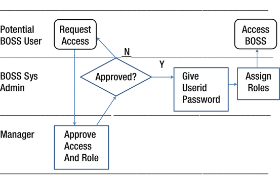
Figure 12-1. Swim lanes
This a simple example, but it illustrates how the different groups of users in this example have the information flows through the system, simple though it is. It starts with a potential user requesting access. Once the manager approves the request and assigns the roles, then the sequence goes through the various tasks to the natural end of the user accessing the system. Notice this example did not provide labels to the tasks as there was not a natural grouping of tasks .
This example has not shown what happens if the user forgets their password. That would be another swim lane chart.
You might ask why the manager would disapprove a request. It is possible the individual is not in the proper department to have access. Other things may happen outside this if the potential user needs to appeal the request. Alternatively, that could be some enhancements you might make to this chart.
What this technique may help with is inefficiencies. Are too many actions happening in one swim lane that is slowing down the process? This technique does not show how long it takes, but you can do some analysis. In this example, once the decision is made, there are only two steps to get the access to the user. However, what if after giving the access, the sys admin had to go back to the manager, or a supervisor to the user, and get the information and then get approval from HR? You see how additional steps cause the sequence to balloon out of control. It is the analysis of the swim lanes where its benefit arises, in addition to the graphical representation to help understand the process.
Warning
This applies not only to this technique but also to virtually all graphical representations. Do not try to represent every task in a system on one swim lane diagram. This would be massive and hard to follow. Like you do in the agile methodology, break them into manageable chunks to aid readability and map more to smaller functions within a project.
You might hear swim lane flowcharts called Rummler-Brache diagrams. Most people take the simpler route and just call them swim lanes.
Since this technique was proposed in 1990, it has become one of the more popular techniques used to supplement requirements, including business analysts using them to depict business process even before requirements definition may begin.
Data Flow Diagrams (DFDs)
In the 1970s, the computer industry embraced Edward Yourdon’s structured analysis. One significant technique to perform this approach to analysis was data flow diagrams. Data flow diagrams show the flow of data within a system in a graphical manner.
Understand that DFDs do not show timing of the flow, or any workflow information such as the sequence as performed in series or parallel.
DFDs start with what is called a level 0 DFD, called a context diagram. This defines the system and its interactions with the external entities, where these entities receive data from the system or send data to them. The only flows depicted on the context diagram are data flows.
Now look at an example of the BOSS Radiation Dosimetry System as was discussed in this book, as shown in Figure 12-2.
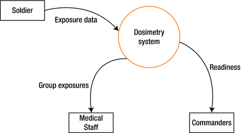
Figure 12-2. Context diagram
To understand the processes within the system, you must expand the system into multiple processes in level 1 (see Figure 12-3).
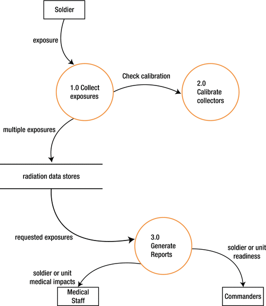
Figure 12-3. Level 1 DFD
You can see how the system is subdivided into processes (the circles), where each process addresses one or more data flows to or from external entities. It also has been identified any internal data stores for the system to perform its functions. Also, any data flows are shown between the internal processes .
First, you need to understand the notation used in the diagram. Accept that you are being exposed to one particular notation, whereas as you research this, if you will use it, there are many tools that use different variations in notations. The notations used here are as follows:
Circles are processes.
Curved lines are data flows.
Rectangles are external entities.
Parallel lines contain the internal data stores.
On the Agile Modeling web page, the “Data Flow Diagram (DFD)s: An Agile Introduction” article gives some excellent common modeling rules for creating DFDs that are highly recommended. These are those rules as presented in the article :
All processes must have at least one data flow in and one data flow out.
All processes should modify the incoming data, producing new forms of outgoing data.
Each data store must be involved with at least one data flow.
Each external entity must be involved with at least one data flow.
A data flow must be attached to at least one process.
Remember, the purpose of the sections in this chapter is to provide supplements to textual requirements that have been discussed up until this point in the book. While there may be some advocates who stipulate some of these techniques may replace textual requirements, this text is not advocating that.
Real-World Note
I used DFDs in my career, in conjunction with a computer-aided system engineering (CASE) tool . (CASE tools are applications designed to help system engineers perform their functions, as you can see from what CASE stands for.) The team spent time creating DFDs after capturing a complete set of shall statements. When we completed this effort, the DFDs were provided to the development team, not to stakeholders.
How low a level you should decompose your DFDs to has not been addressed. The logical answer is as low as you need to go. That said, guidance in the industry is about the third or fourth level. Clearly, if you are down to eight or ten levels, you might want to rethink what you are doing. You are not trying to design a system, just provide information to assist in the development.
Does it seem like this is a good complement to textual requirements? It depends. If you will have significant data stores and manipulation of them, you might want to consider DFDs as a complement to your requirements. Notice that the diagrams are fairly bare of details. DFDs are very useful to depict how data flows within a system, particularly if the project has large, complex data flows. Clearly, a designer might use them, but you will have to decide whether the stakeholders will benefit by them .
Specialized Modeling
Some organizations apply specialized modeling techniques . In that case, you will likely be involved with using them. In some cases, you will prepare the results of your requirement work for the technical consumers using these techniques. Other times, you may be the reviewer of someone else who does the conversion of your requirements to ensure requirements are captured correctly. Or you may just be someone who reads the results of these techniques for informational purposes. In any of those cases, you will need to learn and understand the technique in question.
Also, remember in Chapter 9, we talked about some of the smaller groups within stakeholders such as database administrators, network engineers, system operators, and so on, who are technically savvy? If needed, some of these tools may be useful for them.
This text is only to make you aware of these specialized modeling techniques. There are extensive resources that exist that can aid you in learning about them. The following is a small list of some of the more popular techniques. This is not an endorsement of any of them, as each has their purposes. There are many more that provide the technical data in various formats, both text and graphic representations, to varying degrees of structure. The key takeaway is that some time is needed to use the techniques and understand the data resulting from its analysis.
This section introduces the techniques when you need to write more specialized requirements for the technical audiences:
Unified Modeling Language™ (UML): UML is a modeling language that is intended to analyze requirements to formulate a design, which is managed by Object Management Group (OMG), and now is an ISO standard.
Extensible Markup Language (XML): XML is a markup language to define a file format that is human-readable as well as machine-readable. The document or file does not do anything; it is just a method for representing the file or document.
Rational Unified Process (RUP): RUP is process that added a section specifically for requirements, which is UML based.
State transition diagrams: State transition diagrams show the actions that occur based on specific events, eventually showing all the states of that object. They work well for single objects but are not as effective as many objects are added to a system being analyzed.
System Modeling Language (SySML): SySML is a modeling language for system engineering designed to support all phases of the development lifecycle, including requirement specification. It too is a variation of UML.
This list is certainly not exhaustive but, again, it provides some representative tools that you might use. If they do not serve the needs of situations you encounter, there are other available tools and techniques you can research and employ.
See the reference section for sources that can provide additional information on these subjects .
Tools That Can Aid Requirements Gathering
Affinity diagrams and storyboarding are good tools to use with stakeholders when you are in the process of collecting requirements. In contrast, swim lanes and data flow diagrams are representation methods to use to document requirements after they have been collected to help with the precision of what you have captured. The following two techniques help to drive out the ideas and needs for the system the REs and stakeholders are discussing.
Affinity Diagrams
An affinity diagramis a sophisticated idea for organizing information. You solicit ideas on a particular subject area, whatever it is. You let the people write these ideas, all of them, no matter how outlandish or pie-in-the-sky they may sound. Once you have finished with the idea capture, you now want to bring some structure to them by providing some grouping. It could be one level of grouping or two—whatever works for the group. As a requirements engineer, you may come up with additional refinements to this as your experience tells you, but you should still vet it with the stakeholders.
Therefore, you start with something like Figure 12-4, which shows the results of the brainstorming by the stakeholders dealing with search ideas.
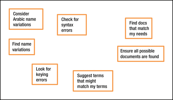
Figure 12-4. Affinity diagram 1
You can see there is no order. After applying some structure, you might have something like Figure 12-5.
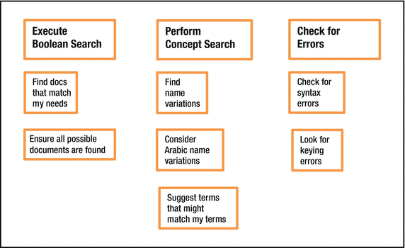
Figure 12-5. Affinity diagram 2
Real-World Note
This is an excellent technique to use in conjunction with brainstorming as I have done on one of my projects. We used the sticky notes people filled out as the foundation for user stories for specific functional areas. We reviewed the results twice after the initial brainstorming to ensure we captured everything correctly.
Just so you know, if you run across the following names, an affinity diagram can also be called an affinity chart or K–J method variation.
Thus, affinity diagrams are an excellent technique to use in requirement elicitation.
Storyboarding
Storyboards are illustrations or images displayed in sequence so you can visualize a motion picture, animation, motion graphic, or interactive sequence. This can include how a human interacts with a computer. Believe it or not, but storyboarding was developed at Walt Disney Productions during the early 1930s. If it works for something as successful as full-length movies or The Three Little Pigs short by Disney, think of the benefit it can bring to system engineering. How can you use it to define requirements?
Before you get to the particular use, make certain you understand what it is.
One aspect of the word storyboard you want to consider is the word story. Just as you captured requirements in user stories, storyboards depict some aspect of the system by showing what some interaction is as a graphic. It could start out as what the user interface looks like, the menu options, whether on the top or bottom of the screen; it may be a snapshot or just hand-drawn on a piece of paper or white board. You can write on, erase, cross out, throw away, or whatever you need to do.
The point is that storyboarding is interactive between the engineers and stakeholders. This type of exchange is informal so that the small group of people feels comfortable enough to provide input. Having been involved with such exchanges, they can be fun. The point is to get the ideas flowing. This is a visual way of brainstorming.
Watch that some people do not dominate the conversation thereby inhibiting others from contributing. It may not be important to drill down all the details for a particular function but to get the general process. You can define the detail later. What is important, say, in a workflow aspect that you saw in a use case, is to show how it flows. It is one thing to read pages of description of what should be done. It is another to see even a crude, hand-drawn representation of it—like how or when the branching of alternatives or exceptions occurs.
You can achieve a consensus from the stakeholders even before a sprint or iteration demo occurs, thereby steering the developers to a more successful sprint. There will be creative and innovative ideas provided that no one may have considered without this specialized brainstorming. Let the ideas flow because you will not know what may come out. The nicest thing to hear is, “How about if we do…?” since this means that people are engaged. That is what you want. After all, your stakeholders will be representative of different types of users, who do not need all the same things or think the same way. You want to have those difference brought out to enhance the storyboards.
Here is a sample storyboard for a piece of software I have worked on. It is not important what this is, other than to see items on the screen.
Figure 12-6 is the first screen, with the main menu, and the crude avatar that will be the user’s guide through the application.
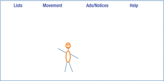
Figure 12-6. Sample main menu screen
Next, each of the four pull-down menus are portrayed as separate storyboards as if someone was sequencing through each of these menus. Figure 12-7 shows the Lists pull-down menu.
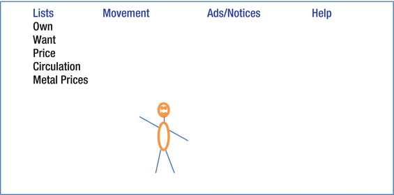
Figure 12-7. Lists pull-down menu screen
Figure 12-8 shows the Movement pull-down menu.
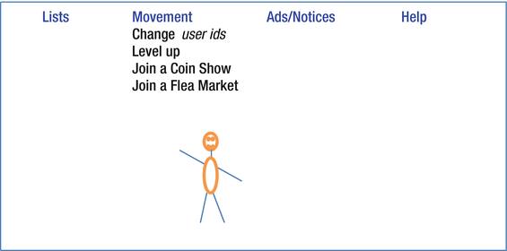
Figure 12-8. Movement pull-down menu screen
Figure 12-9 shows the Ads/Notices pull-down menu .
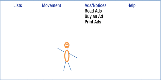
Figure 12-9. Ads/Notices pull-down menu screen
Figure 12-10 shows the Help pull-down menu.
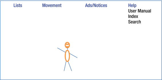
Figure 12-10. Help pull-down menu screen
What would happen is each of the storyboards is shown in the sequence, and the people evaluating them would look at each and discuss each one. They would agree on the sequence of the action, which is an important aspect of storyboarding—showing how the “story” evolves. These same people would then look at each screen and discuss everything that is presented and decide whether everything is in the correct place. Consider whether something needs to be deleted or added.
Once this is done, people could storyboard what happens for each item on these pull-down menus.
This is just one screenshot for the app. The figure in the screenshot is the avatar who guides the user through the application. The words on the top line are the titles of the pull-down menu. The words below are the pull-down menus themselves. Naturally, you cannot pull down all menu options at the same time. It is presented to demonstrate all the anticipated options. You might notice that typical items such as File, with Save, Save As, New, and Print, are not listed. That might be in the future, or it may not apply to this app.
Is this approach something that can aid requirements definition ? At first blush, you could argue that this is for defining the design implementation. In addition, at the surface, yes, that is definitely a significant benefit of storyboarding. Nevertheless, you will learn things that people do not like or things that work well that do contribute to requirements. For example, if someone is talking about how hard the screen looks for doing a search, you realize that the challenge for the user is that the complexity of trying to find “squishy” subjects can be difficult with complex Boolean searches; you realize that concept searches might help. Alternatively, when they are talking that how hard it is to figure out all the nicknames based on proper names like Richard or James or to figure out all the spellings of Mohammed, again a different tool or series of tools besides Boolean may be in order.
Therefore, the answer is that, yes, storyboarding is useful for requirements definition. This is a very useful graphic representation to use. Also, it is fast. You can invest an hour or so but come up with a lot of useful information. It may be useful to have multiple sessions to let people come up with ideas a second or even a third time. When they have a chance to sleep on it, you will be surprised by what happens.
Real-World Note
I write science fiction, and believe me, this storyboarding/brainstorming technique I have used extensively. Having a group of writers brainstorming gets lots of crazy ideas flowing. Most are not applicable, but there are gems that come from it. I have let the ideas, whether just verbally or graphically as in a storyboard, allow me to ferment my ideas to come up with even better ideas. Use the same techniques for software development.
Note
Whereas storyboarding is the beginning of defining some subjects like the user interface, it evolves into prototyping, which was discussed in Chapter 9.
Where does storyboarding end and prototyping begin? Actually, that boundary is blurred. Once someone does some actual coding, even if there is no functionality behind it other than stubs, then you have gotten to the prototyping phase. In addition, prototypes actually can be working flows from one step to another by selecting items. Storyboards do not have that interactive nature. After all, they are just a few related pictures.
Then where does brainstorming end and storyboarding begin? Good question, and about the only distinction that can be made is that if you are gathering ideas with visuals rather than text, you are doing storyboarding.
In summary, yes, storyboarding is a useful tool for requirements definition.
Note
Ambrose Little wrote an interesting article titled “Storyboarding in the Software Design Process” for UX Magazine that you may want to read to get more information about this subject. See the “References” section.
Other Supplements to Requirements Process
The topics in this section don’t directly supplement requirements themselves but provide additional insights into your requirements process. As with the modeling techniques talked about earlier, the intention is not to completely educate you on this topic, but introduce it, in the event that your organization exposes you to it and at least be aware of how it might affect your requirements collection and management.
The topics to be discussed are the following:
Commercial off-the-shelf (COTS)/government off-the-shelf (GOTS)
IEEE standards
ISO 9001
Capability Maturity Model (CMM)/Capability Maturity Model Integration (CMMI) levels of maturity
International Council on Systems Engineering (INCOSE)
Off-the-Shelf Solutions
Off-the-shelf solutions do not directly affect how you create your requirements, but these packages affect how you track your requirements against their implementation. Commercial off-the-shelf software and hardware is just that—something you can run down to your local store or vendor and buy. The simplest example of COTS is Microsoft Office or any of the individual packages such as Microsoft Word. It can be installed on your system, and you can start using it. What does this mean to you as an RE? Now if you were considering installing Microsoft Office or Microsoft Project onto your computer or network, you might not need to specify requirements. However, if you were going to consider procuring a more specialized application for your organization, should you craft requirements for your use? Consider getting a benefits package for your HR department. Absolutely, you should define what your organization needs. Remember, you write requirements to be implementation independent. COTS could be one way to answer the requirements. What you do then is look at COTS packages to see how they compare to your requirements. There are even open source packages that may be zero cost.
Government off-the-shelf packages are produced by a government. Essentially it is a COTS but produced by a government. This means that if you support a government organization (i.e., the federal government, state governments, and even local governments) and if that government produces an application that has utility to other organizations, they have shared it with other government organizations. You would handle any requirements just as you would for a COTS package, craft the requirements, and then look to see whether a GOTS package exists that can be used. This difference may be that you may not need to pay for it.
Real-World Note
For example, I supported an application that provided the ability to apply security classification to documents. This application was shared among more than two dozen portions of the federal government organizations but was developed only once and used by all the organizations. The application started out as a development effort for one agency but was recognized as the best implementation and then was shared with other organizations. Naturally, the requirements were captured once, and then the other organizations received the benefits of them without having to capture their own set, eliminating duplication of effort. I also used some GOTS packages. Again, requirements and development were done once and shared by many. This shows the advantage that requirements can be done once, central and shared with many organizations, and thus the development is also done centrally and implemented consistently.
Once a solution is developed in-house, by a company or governmental entity, other parts of the company or government shouldn’t devote resources for creating something analogous. Additional, the federal government has broadened the use of GOTS for certain related fields. Once the government has paid for a system, other government organizations that perform a common function should not need to pay for the system again. This reduces cost for requirements definition and development, as well as providing consistent implementation, which for certain functions can be very important. This broader use of GOTS shows that governments can perform some things correctly by being innovative.
If you go about your requirements collection properly, when you are done, you can now use your list of requirements to compare various COTS programs to see which ones meet your requirements. Of course, it is likely that not each requirement will be met. You should consider how many are not met and decide what to do with your requirements. Can you live without the remainder? If not, do you want to see whether the vendor will add what you want, especially if you can justify that others might benefit from it? If you cannot live without some of the requirements, as dictated by your stakeholders, then you have to see about getting someone in-house to add it. Thus, you will need to ensure the program has the ability to add features easily, usually called hooks. If not, you might need to consider a different package that does have hooks but a few less of your required features.
Consider an example where you have 100 requirements for a particular application. You find only one COTS package that comes close to your needs. Eight-two requirements are met. What do you do with the remaining requirements? For this example, 16 requirements are specific report requirements that are needed. The application does not provide those reports. However, by examining the reports capability, the COTS package will work with your in-house reporting tool. By having the development team set up reports using the COTS package data, those 16 reports will be provided. That leaves two requirements that are not met. You and your stakeholders will need to decide whether you can live without those capabilities. If so, you are done. If you cannot, then some additional way needs to be found to have the two requirements met. You could ask the vendor to do it, if it is something the vendor believes other customers will use. Or you might have to pay the vendor to do it for you. If that is too costly, you will have to find some way to have them implemented in-house .
IEEE Standards
Remember, Chapter 2 referred to IEEE standard 830-1998. IEEE is the Institute of Electrical and Electronics Engineers, a professional organization of more than 400,000 technical professionals. If your organization follows their standards, then it behooves you to become knowledgeable about these standards and determine how that will affect your efforts. Alternatively, if your organization does not have any standards that it follows, the IEEE may be a source of standards that help improve your organizational processes.
ISO 9001:2008
ISO is the abbreviation used for the International Organization for Standardization. (To have an abbreviation that was consistent for all languages, the organization chose ISO from the Greek isos, which means “equal.”) The point is that ISO is an international organization for standardization, and ISO 9001:2008, “Quality Management Systems - Requirements certificates,” is the standard they have for requirements. If your company uses this as standard, again it behooves you to become knowledgeable of their standards and determine how that will affect your efforts. If your organization does not have a standard, this could be one to consider, especially if you have international dealings. That said, there are some companies that feel the ISO 9001 standard is cumbersome, so be careful. That is not to say do not use it, but look at it carefully. This will fit better with a more traditional waterfall development methodology. With agile, it might inhibit the agile nature of that methodology.
Note
The ISO document does not have a requirements definition and maintenance section; they embedded the requirements discussion throughout the document. Thus, it will take more effort for you as an RE to ensure you are following their guidance for creating and maintaining your requirements.
CMM/CMMI Levels of Maturity
The capability maturity model (CMM) was developed to assess government contractors’ processes to perform on a contracted software project. While it was intended for software development, it can be used for general business process like it has in many government and commercial industries worldwide.
The maturity model is a set of structured levels that describe how well the behaviors, practices, and processes of an organization can reliably and sustainably produce required outcomes.
The CMM model’s application proved to be a challenge. Applying multiple models that are not integrated across the organization can be costly in training, appraisals, and improvement activities.1 The Capability Maturity Model Integration (CMMI) project 2 fixed this problem so that the CMMI model has superseded the CMM model.
The model examines five aspects of your business.
Maturity levels
Key process areas
Goals
Common features
Key practices
The maturity model is a set of five structured levels that describe how well the behaviors, practices, and processes of an organization can reliably and sustainably produce required outcomes. The Wikipedia article “Capability Maturity Model” describes them like this:
Initial (chaotic, ad hoc, individual heroics): The starting point for use of a new or undocumented repeat process. If this is what you have, you do not want to stay here—this is problematic.
Repeatable: The process is documented sufficiently so that repeating the same steps may be attempted.
Defined: The process is defined/confirmed as a standard business process.
Managed: The process is quantitatively managed in accordance with agreed-upon metrics.
Optimizing: Process management includes deliberate process optimization/improvement.
What you will need to know if your organization, or someone you are interviewing with, is CMM level 3 is that means they follow the capability maturity model and you will need to follow it. Do understand that regardless of what level an organization is, it means that the processes work well. The higher the level, the greater chance that the processes do work well, but there is no guarantee. It is not a statement categorically that the product is excellent. It may increase the chances of a better product, but again, it is no guarantee.
The CMMI Institute states that there are three CMMI models. Part of each model shares practices with the other models since these practices apply to any business. Naturally, each model has practices that are unique because each model has a different focus. The three models are
CMMI for Acquisition
CMMI for Development
CMMI for Services
The one most of interest here is the CMMI for Development model, since they designed it for businesses that focus on developing products and services. The process areas that comprise CMMI for Development are Product Integration, Requirements Development, Technical Solution, Validation, and Verification. So, naturally, REs are interest in the Requirements Development process, which will delve into detail about converting customer requirements into requirements used by developers. Thus, if your organization uses CMMI, you will need to follow their processes, so research it well.
Understand that this model fits the waterfall methodology better than the agile methodologies .
INCOSE
INCOSE is the International Council on Systems Engineering, which is not a standards organization but an organization that can be helpful for you in your career and one you should consider joining not only as an excellent resource but also as a good networking source.
On their website, they state, “The International Council on Systems Engineering (INCOSE) is a not-for-profit membership organization founded in 1990. Our mission is to share, promote and advance the best of systems engineering from across the globe for the benefit of humanity and the planet.”
Their vision is to be the world’s authority on systems engineering, and their goals are the following:
To provide a focal point for dissemination of systems engineering knowledge
To promote international collaboration in systems engineering practice, education, and research
To assure the establishment of competitive, scalable professional standards in the practice of systems engineering
To improve the professional status of all persons engaged in the practice of systems engineering
To encourage governmental and industrial support for research and educational programs that will improve the systems engineering process and its practice
They also have student memberships. Here is what it takes to qualify for student membership.
Members qualify for a Student category if they are an undergraduate or master’s or graduate student and if their course load is at least three-fourths of full-time in an engineering or related field. (For example, if the full-time student course load is four per semester, then the student must be enrolled in three or more courses in order to qualify for the student membership rate.)
You may want to consider joining .
References
US Government. “Use Cases”. usability.gov. Feb. 2015, www.usability.gov/how-to-and-tools/methods/use-cases.html
IEEE-SA Standards Board. IEEE Std 830-1998, IEEE Recommended Practice for Software Requirements Specifications. Sponsor: Software Engineering Standards Committee of the IEEE Computer Society, Approved 25 June 1998.
International Organization for Standardization (ISO). ISO 9001:2008 - Quality Management Systems—Requirements. 2008
Phillips, Mike and Shrum, Sandy. “Which CMMI Model Is for You”. August 2011.The CMMI Institute. Feb 2015, http://whatis.cmmiinstitute.com/sites/default/files/documents/Which_CMMI_Model_Is_for_You_2014.pdf
Wikipedia. Capability Maturity Model. Feb. 2015. http://en.wikipedia.org/wiki/ Capability_Maturity_Model
INCOSE. Feb 2015, www.incose.org/
Following are sources to consider for additional information on modeling techniques.
“Data Flow Diagram (DFD)s: An Agile Introduction”. Agile Modeling webpage. Feb. 2015, http://agilemodeling.com/artifacts/dataFlowDiagram.htm
“Swim Lane Diagrams, Mapping and Improving the Processes in Your Organization”. Mind Tools. Feb. 2015, www.mindtools.com/pages/article/newTMC_89.htm
“Introduction to OMG's Specifications: UML”. Object Management Group (OMG). Feb. 2015, www.omg.org/gettingstarted/specintro.htm#UML
“Introduction To OMG's Unified Modeling Language™ (UML®)”. Object Management Group (OMG). Feb. 2015, www.omg.org/gettingstarted/what_is_uml.htm
Beal, Vangie. “XML, a tweet”. Webopedia. Feb. 2015, www.webopedia.com/TERM/X/XML.html
Mullaney, Jennette. “Modeling selection”. SearchSoftwareQuality TechTarget. Feb. 2015, http://searchsoftwarequality.techtarget.com/tutorial/Software-requirements-gathering-techniques
Mullaney, Jennette. “Modeling in the agile methodology”. SearchSoftwareQuality TechTarget. Feb. 2015, http://searchsoftwarequality.techtarget.com/tutorial/Software-requirements-gathering-techniques
Microsoft Development Network webpage, Modeling User Requirements, Visual Studio 2013 Feb. 2015,, http://msdn.microsoft.com/en-us/library/dd409376.aspx
Little, Ambrose. “Storyboarding in the software design process”. UX Magazine. Feb. 2015, http://uxmag.com/articles/storyboarding-in-the-software-design-process
Kruchten, Philippe. “What Is the Rational Unified Process?”. 2001. IBM. Feb. 2015, www.ibm.com/developerworks/rational/library/content/RationalEdge/jan01/WhatIstheRationalUnifiedProcessJan01.pdf
“RUP Fundamentals Presentation”, electronic Research Association (eRA) National Institute of Health. Feb. 2015, http://era.nih.gov/docs/rup_fundamentals.htm
Bell, Donald. “UML basics Part II: The activity diagram”, Sep. 2003. IBM Global Services. Feb. 2015, www.therationaledge.com/content/sep_03/f_umlbasics_db.jsp
“SysML Open Source Specification Project”. Systems Modeling Language (SysML). Feb. 2015, http://sysml.org/
“What is a SysML Requirement diagram and how is it used?”. SysML Forum. Feb. 2015, www.sysmlforum.com/sysml-faq/
