© Joseph Faisal Nusairat 2020
J. F. NusairatRust for the IoThttps://doi.org/10.1007/978-1-4842-5860-6_8

8. Raspberry Pi

Joseph Faisal Nusairat1 
(1)
Scottsdale, AZ, USA
 

Now that we have all the deployments of our code for the backend cloud services, it’s time to dive into the Raspberry Pi (Pi) device itself. This next set of the book will all revolve around coding to the Raspberry Pi device. We will perform a variety of coding tasks on the Raspberry Pi mostly using libraries, some going bare metal. Much of this is to give a glimpse of how we can create a connected environment between device, cloud, and user.

For this first chapter, our major goal is to just get your Pi up and running. Much of the code will be reused from samples from previous chapters. But we will go over enough to make you feel sure-footed and able to run a basic application on the Pi. In this first chapter, we are going to set up the Raspberry Pi in one of the faster ways possible, get it up and running, and then start coding on it. In the last chapter, we will actually optimize this process using buildroot.

Goals

After completing this chapter, we will have the following ready and available:
  1. 1.

    Install Ubuntu Server on our Raspberry Pi and have it working with the local Wi-Fi.

     
  2. 2.

    A Hello World application that is built targeting the Raspberry Pi and runs on there.

     
  3. 3.

    The start of the creation of our client application running on the Pi, which we will build up on throughout the rest of the book.


Raspberry Pi

Let’s start with discussing Raspberry Pi itself and what it is. Raspberry Pis are small single-board devices originally developed in the United Kingdom by the Raspberry Pi Foundation. They first came onto the stage in 2012 and were pretty much an instant hit.

Raspberry Pis filled a void for many different groups. For hobbyist, it was the perfect device due to its small cost but powerful enough you could still easily use it as a small server, serving up microservices or other small stand-alone applications. In fact, when we first started writing this book, we thought of targeting a Raspberry Pi device for the deployment server as opposed to the cloud. There are some secure advantages doing this, since you are inside our own network, which would make it harder to hack. You could do more of your own certificate creations. Then of course, there is the cost you would have the one upfront cost of the Pi and not a monthly cost. In addition to the low cost of the Pis, they can easily be put around the house to perform various functions, often to do with either monitoring or voice interaction, which incidentally are the two items we will be using it for as well.

In addition, they can often serve as prototyping for eventual larger more complex projects. At the car startup I worked, they did just that. When you think about it not only from a cost perspective but time perspective, it makes sense. If you have to prototype, you are going to want the results as fast as possible. In addition, while your hardware team is designing and creating the hardware revisions, you will want to start coding some of the higher-level features as soon as possible. Low-level features may not be compatible depending on what you are doing and the devices you are targeting. But giving you quite a bit of a leg up and in a startup-minded development world, minimizing cost till you get investment is always a good thing.

Let’s dive into creating our Raspberry Pi application.

Create Raspberry Pi Image

In the first chapter, we laid out what you needed to purchase to follow along with this book, until this point we haven’t used any of the parts. That all changes, so get your Raspberry Pi kit out. In this section, we are going to unbox it, power it up, and install a base software image on it that will connect to the Internet. This should give us the first step in running our applications on the Pi.

Unbox the Raspberry Pi

Assuming you purchased the Raspberry Pi and accessories we linked to in the first chapter or an equivalent, we will now start to unbox and use it. Let’s start by reviewing everything we need and will be using throughout the chapter.

Raspberry Pi Kit

The first is the Raspberry Pi kit itself; for this book, we are targeting the Raspberry Pi 4 with built-in Wi-Fi. The processor should be 64-bit architecture, and the speed and and ram of it will vary depending on when you purchased it. But for the examples in the book, I ran it off of a 1.4 GHz processor purchased in 2018. You should be fine along any variant of that. The kit will most likely contain the following:
  • The Raspberry Pi board

  • Heat sinks + glue (or sticky tape on the sink)

  • Power adapter

  • Case

Some specifics may vary depending on the actual Amazon kit you buy, and even though I’ve supplied the URL, the manufacturer may change the specifics. The basics of what was listed earlier will be in all of them though.

As a reminder, the kit can be purchased at https://amzn.com/B07V5JTMV9 or any equivalent by searching for “Raspberry Pi 4 kit”. This will be the board that we run much of the IoT software.

SD Card

A 32 GB SD card comes with the preceding kit. This will be where we store the operating system and the software for running the IoT device as well as storing any data before it reaches the cloud. Raspberry Pis use a microSD card, meaning it won’t directly fit into your computer even if it has an SD card slot. But the kit contains a USB adapter to read the card. If you have an SD card slot reader on your computer, it may be easier to use a microSD to SD adapter that you can purchase fairly inexpensively here: https://amzn.com/B0047WZOOO.

Debug Cable

Lastly is the debugging cable; this is going to be necessary when we set up the server in the beginning, and it’s just a useful tool to have for any debugging later on that is needed. As a reminder, you can purchase this cable at https://amzn.com/B00QT7LQ88.

Assembling Raspberry Pi

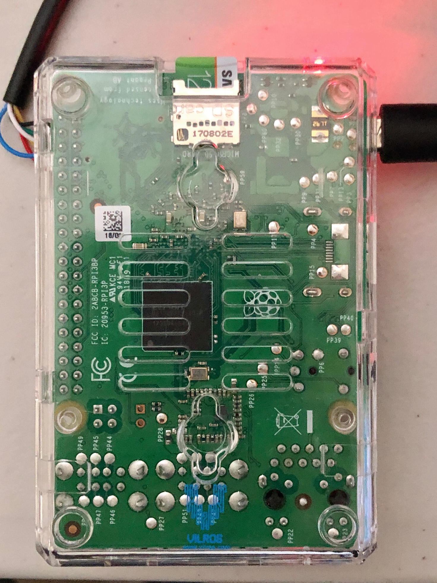
The Raspberry Pi itself is fairly easy to assemble; take the two heat sinks and they will either have a sticky back tape to pull off or glue in the kit. If there is a sticky back tape, take it off and put it on the two silver chips. If there is glue, you first place the glue on the heat sink and then apply the heat sinks directly to the chips.

Once the heat sinks are attached, we can then put the board in the case and snap the top. This gives us a nice little case without anything exposed and will also minimize our risk of touching the board directly and having a static discharge.

In Figure 8-1, we have the finished product of the Pi 4 board with heat sinks attached.
../images/481443_1_En_8_Chapter/481443_1_En_8_Fig1_HTML.jpg
Figure 8-1

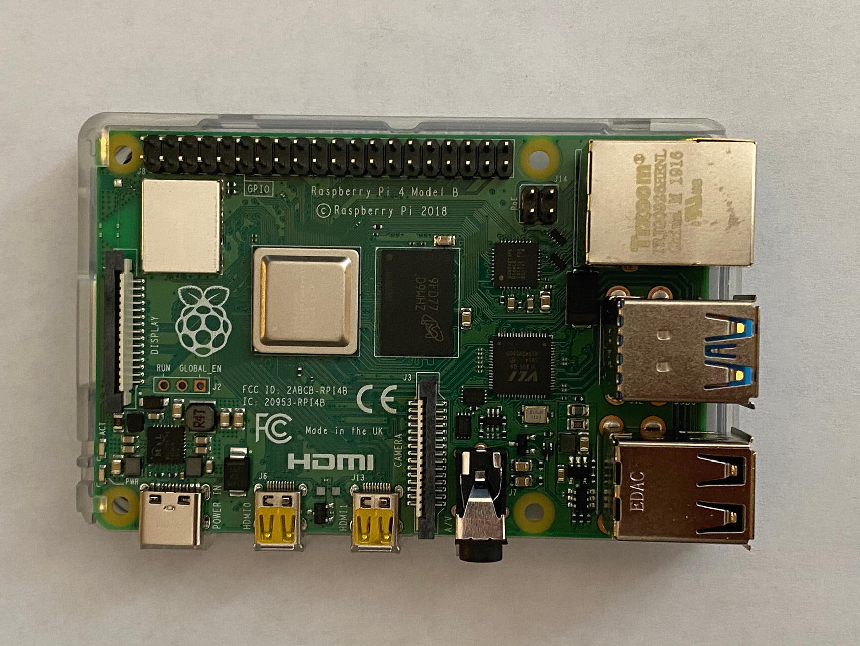
Shows the board with the heat sinks attached

Let’s take another look at the board; in Figure 8-2, I have an overview picture of the board with various parts on the board labeled. Let’s go over what some of those parts are.
../images/481443_1_En_8_Chapter/481443_1_En_8_Fig2_HTML.jpg
Figure 8-2

Shows the board labeled by items (this is a Pi 3 board but close to the 4)

Let’s start on the top and work our way around the board:
  • GPIO – Is an 85 mm general-purpose input/output set of integrated circuits that we will use to integrate with the board. These are unused by default, but we can use them to perform interactions with our board.

  • Controller – The controller for the USB and Ethernet LAN ports.

  • USB – On the side, we have two sets of two USB ports.

  • Ethernet – The bottom is our 10/100 Ethernet LAN port.

  • Audio – Is a 3.5 mm four-pole video and audio socket.

  • CSI camera port – A port we can attach our camera to.

  • HDMI – An HDMI port that will allow us to attach the board to a monitor or TV.

  • Micro USB power – A 5V micro USB that can be used to power the board.

  • MicroSD card – On the underside of the board is where we put the card that we will create in a bit.

  • Wireless – The wireless controller for the board. This runs the 2.4 GHz and 5 GHz 802.11 Wireless LAN and Bluetooth-supported controller.

  • Processor – The Broadcom BCM283780 Cortex-A57 64-bit SoC 1.4 GHz 1 GB Ram chip.

GPIO

On the top of the board is the GPIO pins, which we will use to interface with the board in this and later chapters. Each of those represents different pins that are used for communication with the board, powering the board, or for grounding. In Figure 8-3, we have a map of the GPIOs and what they represent.
../images/481443_1_En_8_Chapter/481443_1_En_8_Fig3_HTML.jpg
Figure 8-3

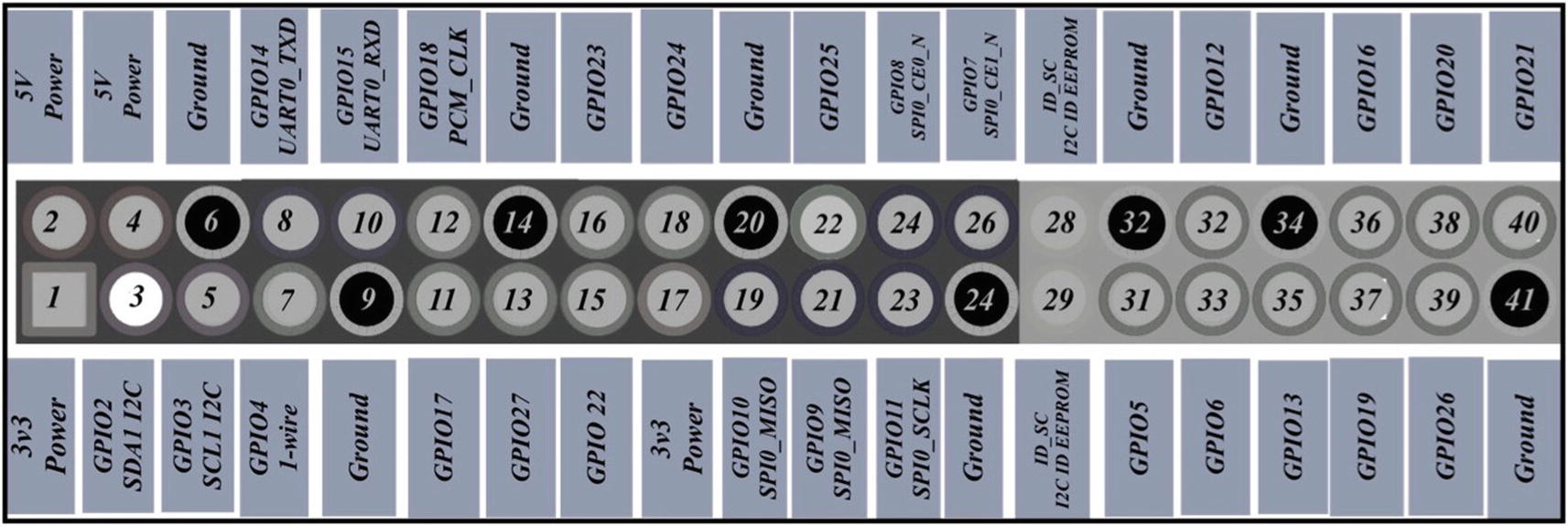
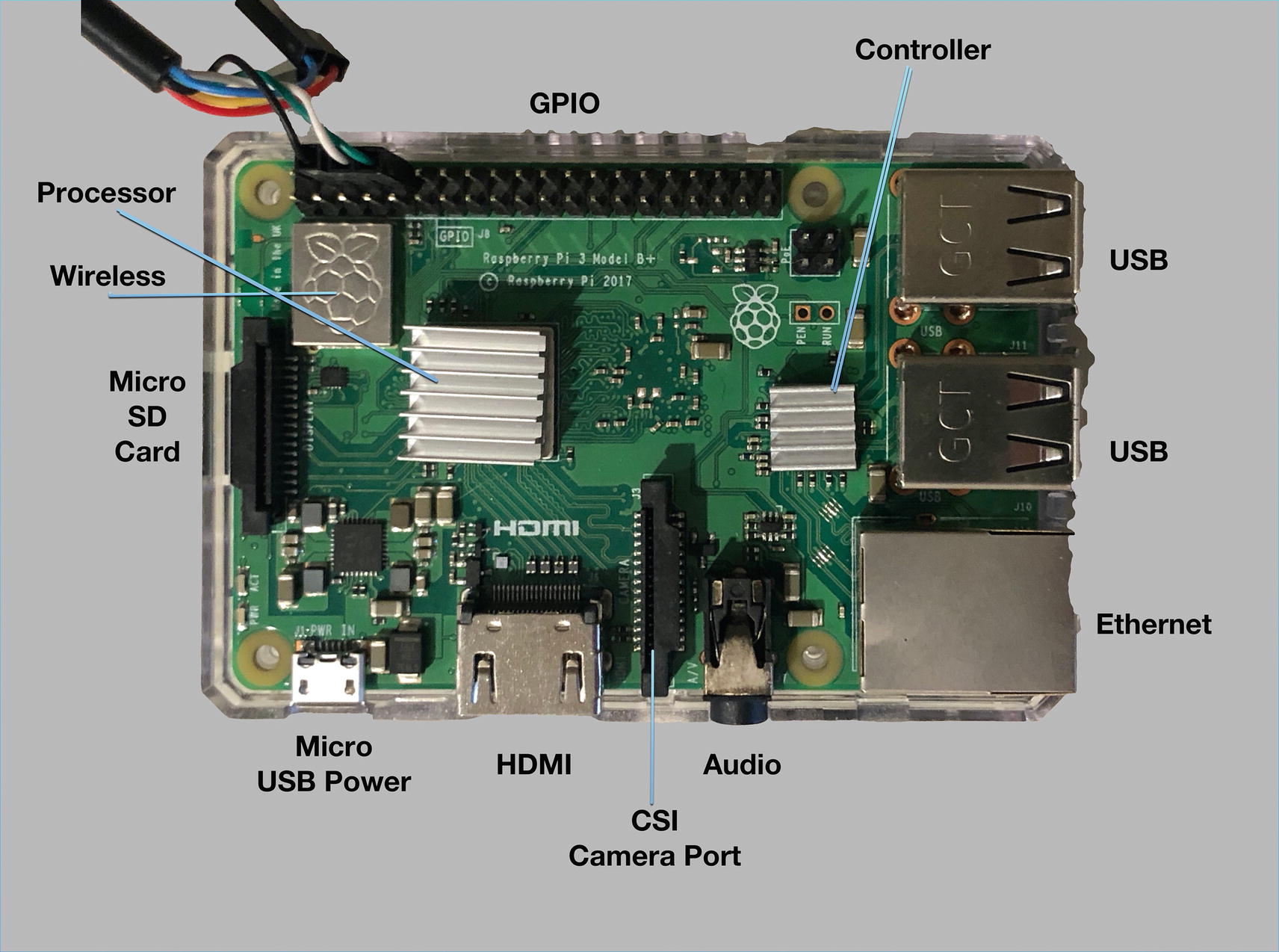
Shows the GPIO layout of the board

You will notice the number 2 and 4 slots are 5V leads. These can be used to power the peripherals on top or be used to actually power the board from an external source like a USB. Another two interesting slots are the 8 and 10. These are the UART slots. UART stands for Universal Asynchronous Receiver/Transmitter and is used to transmit data between devices. The one lead transmits and the other receives serial data. The data is transmitted asynchronously, so that means there is no clock signal to synchronize with. We don’t use these much anymore for modern computers, but they used to be used for mice, printers, and modems before we had USB.

We will use these though for our initial communication with the board before we have our shell ready. At this point, you can attach your USB debug cable to the board. Attach the cables to the following parts:
  • Black cable – Is our ground cable and should be plugged into the 6 pin

  • White cable – Is our transmitter cable and should be plugged into the 8 pin

  • Green cable – Is our receiver cable and should be plugged into the 10 pin

The end result is your cables should look like Figure 8-4.
../images/481443_1_En_8_Chapter/481443_1_En_8_Fig4_HTML.jpg
Figure 8-4

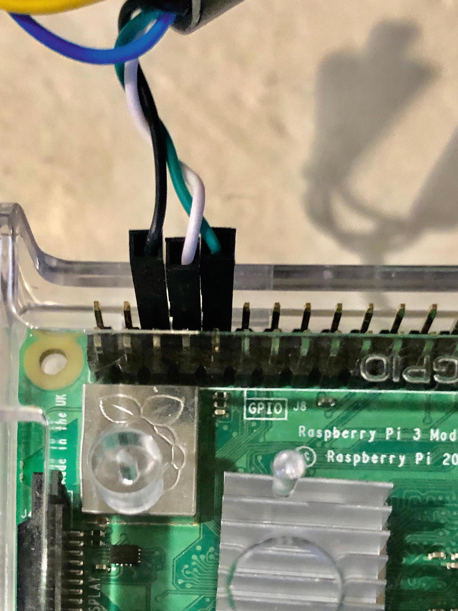
Our debug cable attached

You could in addition attach the red cable to the 2 pin, but we are going to just plug the board in since once we get it configured, we won’t need to directly attach again, but in theory we could power the board from our computer.

We now have our board all set up and ready to be used; of course, nothing is on it right now, so let’s take the microSD card format it and put an operating system on top of it.

OS Software

Let’s now get into the nuts and bolts in setting up our Raspberry Pi, getting the operating system software installed. Much like buying your standard desktop computer, there are many variants of operating systems to install. There is the standard Raspbian which is the official operating system for all Raspberry Pis. There is also Mozilla OS, and even Windows has a specialty Windows 10 IoT core dashboard; as you can imagine since you are reading this book, Raspberry Pis are great for IoT devices. We are going to stick with the standard out-of-the-box Raspbian for this application. Performing builds in future chapters is a bit easier using Raspbian as well.

You can view all the possible operating systems you can install at www.raspberrypi.org/downloads/. The top of the page has the Raspbian link we are going to select; the output of that page looks like Figure 8-5.
../images/481443_1_En_8_Chapter/481443_1_En_8_Fig5_HTML.jpg
Figure 8-5

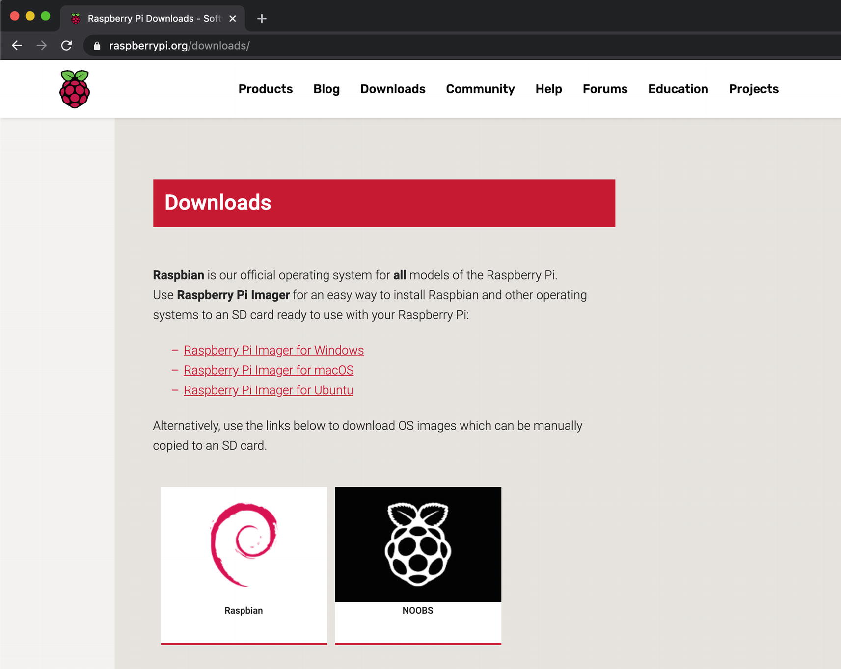
The Raspberry Pi operating system list page

Go ahead and click “Raspbian” link and scroll down a bit; you will see a screen that looks like Figure 8-6 showing the three different Raspbian versions to select from.
../images/481443_1_En_8_Chapter/481443_1_En_8_Fig6_HTML.jpg
Figure 8-6

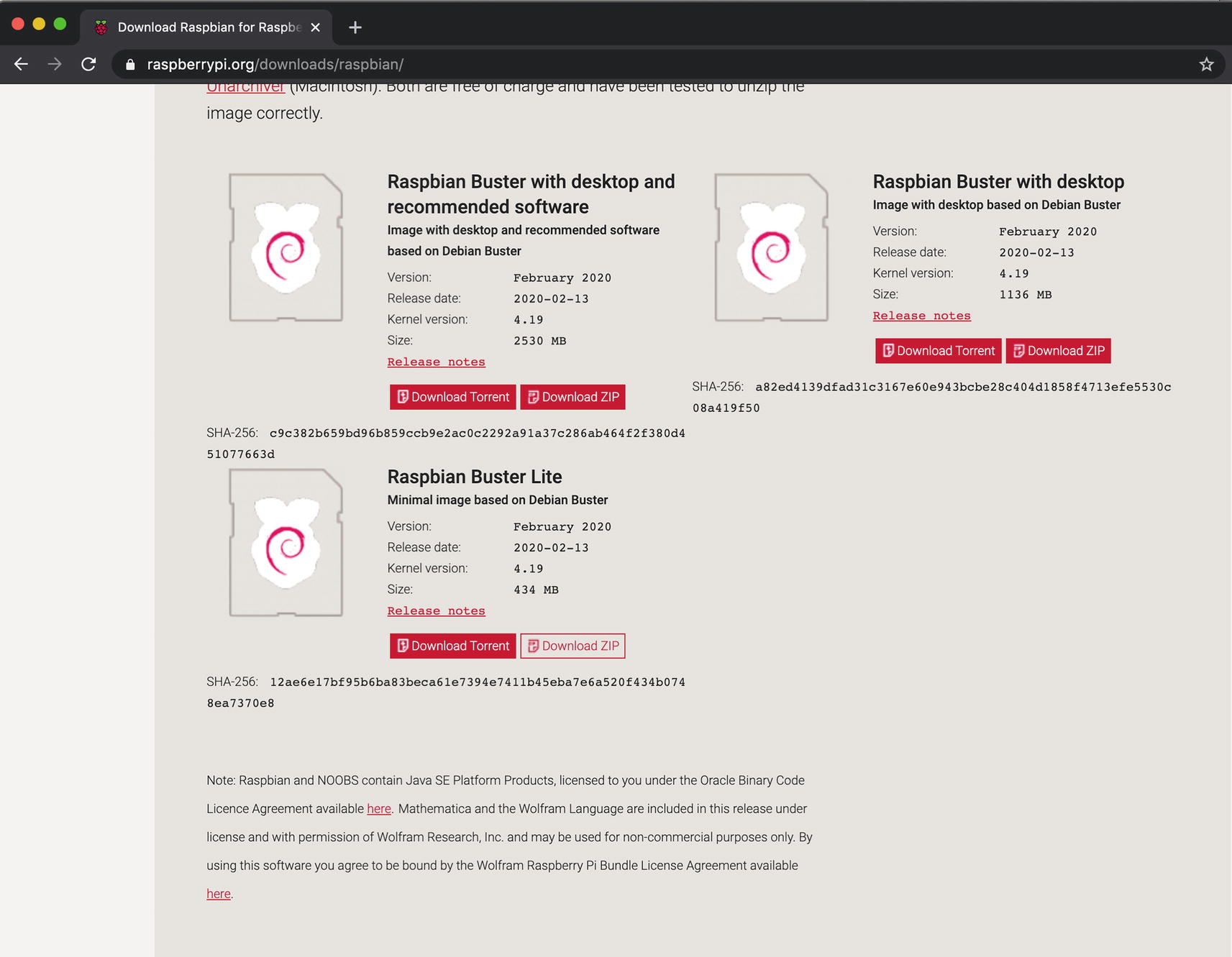
The various Raspbian installs

Our Pi won’t be designed to hook up to a monitor; this is going to run code that we customize for it. For that case, all we need is the “Raspbian Buster Lite” version. Click the Download like for the ZIP version and you should have downloaded a file that looks like 2020-02-13-raspbian-buster-lite.zip; the exact version may differ based on when you have reached this page. Raspbian is a derivation of the 32-bit Debian operating system, so many of the tools we use on Debian, we will use on Raspbian.

Installing the Software

Once the file is downloaded, we will take it through a few steps:
  1. 1.

    Unzip the compressed image.

     
  2. 2.

    Wipe our microSD card.

     
  3. 3.

    Install the image onto our microSD card.

     
Unpack the File

Once the file is downloaded, you can check the sha256sum to ensure the integrity of the download. You can find the shasum on the same link we downloaded and then run sha256sum on the file to verify the file. But assuming it is fine, let’s unzip it like we are doing in Listing 8-1.

You can choose either the 18.04 or the 19.10 version; I would recommend the 18.04 because it will ensure the software you are writing to will be supported the longest.
➜ unzip 2020-02-13-raspbian-buster-lite.zip
Archive:  2020-02-13-raspbian-buster-lite.zip
  inflating: 2020-02-13-raspbian-buster-lite.img
Listing 8-1

Unzipping the Raspbian server

This unzips the file, and you will be left with an image file 2020-02-13-raspbian-buster-lite.img.

Wipe and Initialize the SD Card

Now let’s get the card ready to run the OS on our Pi. The card you bought should come blank, but too often they have drivers or other software on them usually for Windows computers. We want to blank them out and start fresh. The following code will initialize the disk but is specific for macOS using diskutil; the equivalent in Linux will be fdisk (with some slightly different options).

Plug in your adapter and your SD card in the adapter. In Listing 8-2, we are going to find where the device is attached to. Now your exact structure may look different than mine, so we will try to find the similarities.
➜ diskutil list
/dev/disk0 (internal, physical):
   #:      TYPE NAME                           SIZE         IDENTIFIER
   0:      GUID_partition_scheme               *500.3 GB         disk0 ①
   1:      EFI EFI                             314.6 MB        disk0s1
   2:     Apple_APFS Container disk1           500.0 GB        disk0s2
/dev/disk1 (synthesized):
   #:      TYPE NAME                           SIZE          IDENTIFIER
   0:      APFS Container Scheme -             +500.0 GB          disk1
           Physical Store disk0s2
   1:      APFS Volume Macintosh HD - Data     465.2 GB         disk1s1 ②
   2:      APFS Volume Preboot                 104.2 MB         disk1s2
   3:      APFS Volume Recovery                1.0 GB           disk1s3
   4:      APFS Volume VM                      8.6 GB           disk1s4
   5:      APFS Volume Macintosh HD            10.9 GB          disk1s5
/dev/disk2 (disk image):
   #:      TYPE NAME                           SIZE         IDENTIFIER
   0:      GUID_partition_scheme               +2.8 TB           disk2 ③
   1:      EFI EFI                             209.7 MB        disk2s1
   2:      Apple_HFS Time Machine Backups      2.8 TB          disk2s2
/dev/disk4 (external, physical):
   #:      TYPE NAME                           SIZE         IDENTIFIER
   0:      FDisk_partition_scheme              *32.0 GB          disk4 ④
   1:      Windows_FAT_32 system-boot          268.4 MB        disk4s1
   2:      Linux                               31.8 GB         disk4s2
Listing 8-2

Getting the list of disks attached to the computer

  • ➀ Our main internal disk.

  • ➁ The disk that contains your hard drive OS and so on.

  • ➂ Time Machine drive if you had it attached.

  • ➃ The SD card attached.

The contents of the SD card you have will depend on the exact layout of your disk and what’s default software is on there. Some come completely blank, and others have initialization software. The most important thing is to identify which disk you have; the last thing you want to do is erase another disk. During this process, I recommend also disconnecting any other external drive so as not to confuse yourself since the next few steps are destructive.

It’s somewhat easy to spot the SD card on here by the size; you notice the 128.0 GB which is the size of the SD card I purchased for this. The SD card is on /dev/disk4; you will need this for the rest of the calls we are going to make.

Next, let’s erase the SD card and put a FAT32 filesystem on top of it instead. In Listing 8-3, we erase the disk targeting /dev/disk4, installing FAT32 as the file system. Remember this phase permanently erases the data, proceed at caution, and make sure you have the right disk.
➜ diskutil eraseDisk FAT32 EMPTY /dev/disk4
Started erase on disk4
Unmounting disk
Creating the partition map
Waiting for partitions to activate
Formatting disk4s2 as MS-DOS (FAT32) with name EMPTY
512 bytes per physical sector
/dev/rdisk4s2: 249610688 sectors in 3900167 FAT32 clusters (32768 bytes/cluster)
bps=512 spc=64 res=32 nft=2 mid=0xf8 spt=32 hds=255 hid=411648 drv=0x80 bsec=249671680 bspf=30471 rdcl=2 infs=1 bkbs=6
Mounting disk
Finished erase on disk4
Listing 8-3

Erasing the SD card with FAT32 on top

At this point, the disk is erased and formatted to a FAT32 file system, but the disk is still mounted to our directory structure. We will need to unmount it before we install the image. In Listing 8-4, we unmount the disk.
 diskutil unmountDisk /dev/disk4
Unmount of all volumes on disk4 was successful
Listing 8-4

Unmount the disk

Instructions on Erasing on Linux
The preceding data shows how to perform this operation on the Mac, and the following data will present how to perform this same series but on a Linux box:
- In order to list the disk contents, you will use "fdisk –l" which will list all your disks (we will assume "/dev/disk4" is the location).
- Enter fdisk /dev/disk4" to put the console in an interactive mode, selecting "d" to select the partition. You will then be given a list of partitions to delete; if just one, select "1". Keep going through the rest of the partitions till they are all deleted.
- Now we want to create a new partition, type "n" for new and then "p" to create the primary partition. You will have to enter "1" to make this the first partition and hit Enter. After that, it will ask you to set the first and last cylinder; just click Enter to select the defaults. When you are finally done, you will enter "w" to write the new partition to the SD card. At this point, your partition should be ready.
- Type "unmount /dev/disk4" to unmount the disk and prepare it for FAT32 creation.
- We will use "mkfs.vfat" to make a FAT32 partition. Enter "mkfs.vfat -F 32 /dev/disk4" and that will put a FAT32 on your SD card.
Install Image
Finally, let’s put the image on our application. In Listing 8-5, we will use the dd command to install the image onto our SD card.
➜ sudo dd bs=4m if=./2020-02-13-raspbian-buster-lite.img of=/dev/disk4 conv=sync
739+1 records in
739+1 records out
3102821376 bytes transferred in 967.374066 secs (3207468 bytes/sec)
Listing 8-5

Installing the RasPi image onto the card

This will take a little bit of time, so be patient once you hit Enter. Also, depending on if you are using Linux or OSX, there are a few errors you may get; these instructions are for OSX, but a few errors and the resolutions you may find:
  • dd: bs: illegal numeric value – Adjust your 4m to a smaller value; conversely, one could have a larger value if you get no error. But 4 seemed to be fine for my needs.

  • dd: unknown operand status – On the 4m, change it to capital M; on Linux it usually wants a capital M and on OSX a lowercase m.

The “conv=sync” at the end is to make sure the writing is absolutely complete and all the buffers flushed. This way, we don’t inject the SD card with some writing still occurring. At this point, our card should have the base Pi image on it.

If you look at your list of volumes, you should have one that is called boot now. This is where the files the Raspberry Pi will boot from. One that will be of importance to us later is the config.txt. We will update it for certain configuration changes later. For now, just put a blank file into the root of the boot volume called ssh (touch /Volumes/boot/ssh if on a Mac). This file being there will allow us later to be able to ssh into the Pi.

Final Setup Steps

Now that we have our SD card ready, it’s time to remove it and insert it into the Pi. The SD card in your computer won’t fit, but the microSD card will. Remove it from the SD card, and put it into the slot on the underside of the Pi. Once that’s inserted, plug in the power cable to the USB power slot, and you can plug the power cable into the wall at this point too, which is what we have in Figure 8-7.
../images/481443_1_En_8_Chapter/481443_1_En_8_Fig7_HTML.jpg
Figure 8-7

The microSD card installed into our Raspberry Pi

We now have our Pi up and running, and if you plugged in an Ethernet cable, it would be attached to the Internet. We could actually log into it that way as well. However, we want it to work on Wi-Fi so we can use it anywhere in the house. Let’s take that USB debug cable that’s already attached to your Pi and connect it to your computer. This will allow us serial access onto the board. We will need to do a few things to get this serial connector work since by default most apps don’t speak serially anymore. We will need a serial terminal app.
  1. 1.

    Determine the serial name for the USB plugged in.

     
  2. 2.

    Install an application that will allow us virtual terminal access.

     
Plug the USB cable into your computer; the Pi can be on or off at this point. You will be able to look for all the devices both virtual and connected under the /dev directory, but this one will be tagged as usbserial. We will need to know the device name so that we can tell our application which serial connection to connect to. In Listing 8-6, we do a listing of our directory to find the name of all usbserials.
➜ ls -al /dev | grep cu.usbserial
crw-rw-rw-   1 root    wheel       18,  13 Nov  2 18:46 cu.usbserial-14340
Listing 8-6

Find the USB serial connector

Assuming you only have one connected, you will only have one entry to contend with. If you get more, disconnect other USB serial devices. Now let’s install an application that will let us perform the serial connections. There are two different applications we can install, screen or minicom; for our purposes, let’s install screen; you can do this by these:
  • On OSX – brew install screen

  • On Linux – sudo apt-get install screen

We will now connect to the port (you can do this while the Pi is off, just nothing will show). The screen command takes two parameters: the connection and a baud rate; the baud rate for our Pi is 115200. Call the command screen /dev/cu.usbserial-14340 115200 from a terminal window (at this point, make sure you are plugged in; if not, you will just see a blank screen). Now you will see a terminal screen like in Figure 8-8. Since this is our first time with the new OS, you may see quite a bit of verbose messages before we get to a prompt.
../images/481443_1_En_8_Chapter/481443_1_En_8_Fig8_HTML.jpg
Figure 8-8

Screen capture from USB cable debug login

In order to log in, you will use the default username pi and the password `raspberry`; after your first login, you should change your password. That initial login screen should look like Listing 8-7.

Make sure the terminal screen is on your primary screen; I had issues with the password accepting when not on the primary screen.
Raspbian GNU/Linux 10 raspberrypi tty1
raspberypi login: pi
Password:
Linux raspberry pi 4
pi@raspberrypi:~ $ passwd
Changing password for pi.
Current password:
New password:
Retype new password:
passwd: password updated successfully
pi@raspberrypi:~$
Listing 8-7

Login screen on your initial logging to the Raspberry Pi

At this point, we can quickly check the status of our Internet connection with the command ip address; in Listing 8-8, we run the command with the following output.
pi@raspberrypi:~$ ip address
1: lo: <LOOPBACK,UP,LOWER_UP> mtu 65536 qdisc noqueue state UNKNOWN group default qlen 1000
    link/loopback 00:00:00:00:00:00 brd 00:00:00:00:00:00
    inet 127.0.0.1/8 scope host lo
       valid_lft forever preferred_lft forever
    inet6 ::1/128 scope host
       valid_lft forever preferred_lft forever
2: eth0: <NO-CARRIER,BROADCAST,MULTICAST,UP> mtu 1500 qdisc fq_codel state DOWN group default qlen 1000
    link/ether b8:27:eb:5b:1e:80 brd ff:ff:ff:ff:ff:ff
3: wlan0: <BROADCAST,MULTICAST> mtu 1500 qdisc noop state DOWN group default qlen 1000
    link/ether b8:27:eb:0e:4b:d5 brd ff:ff:ff:ff:ff:ff
pi@raspberrypi:~$
Meta-Z for help | 115200 8N1 |
Listing 8-8

Checking the connection status of Internet-connected devices

You will notice that while we have a wireless connection with wlan0, we have no actual IP address; that is because we have not configured it to log into your Wi-Fi router.

Set Up Wi-Fi

Let’s set up the wireless router; now these set of instructions will assume you have a password protection on your home router. This will be a two-step process; the first step will be to add a file that contains our wireless SSID and the password. The second step will be to then reboot the Pi to have everything take effect.

First things first – we are going to update the cloud initialization file /etc/wpa_supplicant/wpa_supplicant.conf to store our wireless connection information. The file may have a few lines of details in it; we are going to add network configurations to it for our wireless Ethernet settings; you will have to log in as sudo (sudo su - is a good way to get into super user mode) and update the file so it looks like Listing 8-9.
pi@raspberrypi:~$ sudo su -
pi@raspberrypi:~$ vi /etc/wpa_supplicant/wpa_supplicant.conf
network={
    ssid="Nusairat Wireless" ①
    psk="testingPassword" ②
}
Listing 8-9

Creating our wireless connection file

  • ➀ Is the name of your wireless SSID?

  • ➁ Is the password for your wireless SSID (mine isn’t really just a password; it’s 1-2-3-4)?

At this point, you can reboot the Pi with the command reboot and then log back in. Now when you do ip address, you should see an actual ip address; try performing a ping google.com to verify you are reaching the Internet. Also make note of your IP address; we will use that later.

Now if that doesn’t work, it could be because you have a block on your wireless connection. Log in as sudo and run rfkill -list; if you see anything marked “yes” under the Wireless LAN, we are going to need to unblock it. On the version I had, there was a soft block on the Wireless LAN; thus, we couldn’t start up the wireless connection. In order to remove that block, run rfkill unblock 0 to unblock it, and now let’s start up the Wireless LAN with ifconfig wlan0 up. I’ve put these commands into Listing 8-10 to make it easier to follow along and try. Now if you reboot, your wireless connection should be up and ready to use.
root@ubuntu:~# sudo su -
pi@raspberrypi:~ $ rfkill list
0: phy0: Wireless LAN
    Soft blocked: yes
    Hard blocked: no
1: hci0: Bluetooth
    Soft blocked: no
    Hard blocked: no
pi@raspberrypi:~ $ rfkill unblock 0
pi@raspberrypi:~ $ ifconfig wlan0 up
pi@raspberrypi:~ $ reboot
Listing 8-10

Contents of wpa-wlan0.conf

OK, so now we have a Pi that has Internet access and importantly local access. Now we will be able to ditch the USB serial cable and log directly onto the board. (Note: The debugging cable can still come in handy, and you don’t have to worry about SSH timeouts either.)

Setup SSH Access

You can now try to SSH into the box on your own; simply type ssh ubuntu@<the ip you wrote down earlier>. We can obviously do this by using the IP address and using the password each time, but this can get quite tedious over time.

Let’s do a few things to make our life easier. First off, the IP address (the one I asked you to remember) that’s hard to remember every time, let’s give ourselves a shortcut for it in. In your /etc/hosts file, you can add host names to map to IP addresses. In Listing 8-11, I map pi to the ip address and add that entry to /etc/hosts file. (Note: You will have to do sudo vi /etc/hosts to edit it.)
pi 192.168.7.70
Listing 8-11

Add pi to your /ets/hosts

Now in order to ssh to the box, all we have to do is ssh ubuntu@pi; you can go ahead and try it, but unfortunately, we still have to enter our password, and that can be annoying itself. This will become even more annoying as we make builds and send them to the Pi for testing. Let’s fix this by telling our Pi that the public key from our computer has access to the Ubuntu account on the Pi always. If you use Gitlab or any git instance, you probably have your public key created already. If you have, just skip to “Update Authorized Keys”; if you don’t, read on and we will set up the public key. If you aren’t sure if you have a public key, perform ls ~/.ssh, and if you get no files returned, then you don’t, and we will need to set it up.

Generating a public key on a Linux/OSX is fairly simple and identical; there are luckily built-in commands to create the keys. You can use the command ssh-keygen to generate the key; I would save it in the default location; if not, the rest of the instructions won’t work. But now, you can run cat ~/.ssh/id_rsa.pub and should have your keys installed.

Update Authorized Keys

Now that we have a key, we are going to copy this over to the Pi and store it in the ~/.ssh/authorized_keys location. This will tell the server that any request with that key as its SSH key will be authorized without requiring login. In Listing 8-12, get the contents of our local id_rsa.pub and copy it over to the Pi.
~ ➜ ssh-copy-id -i ~/.ssh/id_rsa.pub pi@pi
The authenticity of host 'pi (192.168.7.70)' can't be established.
ECDSA key fingerprint is SHA256:UnLvF5X/5yFzGgGFkM0i7DK4lOR3aU3SH+okDAySf4c.
Are you sure you want to continue connecting (yes/no)? yes
Warning: Permanently added 'pi' (ECDSA) to the list of known hosts.
pi@pi's password:
Number of key(s) added:        1
Now try logging into the machine, with:   "ssh 'pi@pi'"
and check to make sure that only the key(s) you wanted were added.
Listing 8-12

Run this command from your computer to the Pi

You will have to enter the password one last time in there. But after this is done from your computer, run ssh ubuntu@pi, and you will be able to access your Pi without any password or remembering the IP address each time. Do remember though if the Pi’s IP ever changes, you will have to update your /etc/hosts. Now that we have the Pi ready, let’s start installing software.

Client Application

Now that we have the Pi all set up and we can log onto it, let’s start to get code written to go on the Raspberry Pi device. We are going to write two applications for this section. The first one is a simple hello world, just to see how a simple application works on the Pi. The second will be the start of our full-fledged application.

Hello World Application

Let’s start with the simple hello world application. It’s our basic hello world that gets created when we run cargo new hello-world. Go ahead and create one right now; our issues are going to be in deploying, not creating the application. In Listing 8-13, we will build the application and copy it the Raspberry Pi.
➜ cargo build ①
    Finished dev [unoptimized + debuginfo] target(s) in 0.06s
➜ scp target/debug/hello-world ubuntu@pi:/home/ubuntu/hello-world ②
Listing 8-13

Build Hello World and copy it to the Pi

  • Build our hello world application.

  • Copy the created target to the Raspberry Pi home directory for Ubuntu.

Now that the file is there, open up another terminal window, ssh into the box, and run the application. In Listing 8-14, you will see the result of that action.
➜ ssh ubuntu@pi
Welcome to Ubuntu 19.10 (GNU/Linux 5.3.0-1007-raspi2 aarch64)
ubuntu@ubuntu:~$ ./hello-world
-bash: ./hello-world: cannot execute binary file: Exec format error
Listing 8-14

SSH and run the Hello World on the Pi

Well that didn’t work, did it? This should not seem like too much of a surprise if you understand Rust; like most compiled languages, they are targeted to a platform. We will need to target this for Raspberry Pi.

Cross Compiling

With rustup, we can cross compile our applications to work on other systems, and in this case, we are going to target the Raspberry Pi Ubuntu system. In Listing 8-15, we are going to add and target armv7-unknown-linux-musleabihf.
➜ rustup target add armv7-unknown-linux-musleabihf
info: downloading component 'rust-std' for 'armv7-unknown-linux-musleabihf'
 12.6 MiB /  12.6 MiB (100 %)   6.7 MiB/s in  2s ETA:  0s
info: installing component 'rust-std' for 'armv7-unknown-linux-musleabihf'
Listing 8-15

Installing the armv7-unknown-linux-musleabihf target

If you are using a Windows computer, run rustup target add armv7-unknown-linux-gnueabihf. Now that the target is installed, we need to define it as a possible target to use for the application that will also define the linker to use. You can define the targets to build in ~/.cargo/config. In Listing 8-16, we define the linker to use.
[target.armv7-unknown-linux-musleabihf]
linker = "arm-linux-gnueabihf-ld"
Listing 8-16

Defining the linker in .cargo/config

Now what does all this mean? The names? The linker? What we are defining is the cross compiler we are going to use to create a secondary target to build the application. Let’s take a look at the name of the linker we added. This name isn’t random; it’s actually a specific name that makes up four different attributes that are put together in a format of {arch}-{vendor}-{sys}-{abi}1:
  • arm – The architecture we are targeting. Raspberry Pis use an ARMv7 development board.

  • vendor – The vendor, in many cases, is optional; in those cases, it is marked as unknown.

  • sys – The system we are compiling to, since we are deploying it to an Ubuntu Linux system, “linux”.

  • abi – The system that indicates the C library we are using for the cross compiling. In our case, it is the Musl GCC cross compiler; if you want more information on this library, you can read about it here: https://wiki.musl-libc.org/getting-started.html.

We can build this against that target by adding the flag --target armv7-unknown-linux-musleabihf to our cargo build. If we did this, we would get the error in Listing 8-17.
 cargo build --release --target armv7-unknown-linux-musleabihf
   Compiling hello v0.1.0 (/Users/jnusairat/temp/hello)
error: linker `arm-linux-gnueabihf-ld` not found
  |
  = note: No such file or directory (os error 2)
error: aborting due to previous error
error: Could not compile `hello`.
To learn more, run the command again with --verbose.
Listing 8-17

Defining the linker in .cargo/config

This error is because of our indirect use of the ring crate; the ring crate is used for cryptographic operations and is fairly a common library to use for any type of certificate use or other crypto functions. This software uses a mixture of Rust and C code, which means in order to compile, you will need a C cross compiler. To that end, we will have to add musl-gcc. Let’s install the cross compilers. In Table 8-1, we list the commands for installing on Linux, OSX, and Windows (please note I only have a Mac so that’s what I tried it on).
Table 8-1

GCC cross compilers for arm

System

Command

OSX

brew install arm-linux-gnueabihf-binutils

Linux

sudo apt-get install gcc-arm-linux-gnueabi

Windows

Will need to install the Raspberry Pi tool chain from https://gnutoolchains.com/raspberry/.

Run the command based on the computer you are on. Now that you have the tools installed, let’s try to rebuild the application. In Listing 8-18, we rerun the builder.
➜ cargo build --release --target armv7-unknown-linux-musleabihf
   Compiling hello-world v0.1.0 (/Users/joseph/Library/Mobile Documents/com~apple~CloudDocs/work/rust-iot/code/ch08/hello-world)
    Finished release [optimized] target(s) in 4.57s
➜ ls -al target/armv7-unknown-linux-musleabihf/release/hello-world
-rwxr-xr-x  2 joseph  staff  2774584 Nov  4 19:02 target/armv7-unknown-linux-musleabihf/release/hello-world
Listing 8-18

Defining the linker in .cargo/config

Success! You will also notice I compiled for a release profile; I do this because I wanted an optimized build, and also we haven’t defined anything yet for a dev profile (but you could have just as easily removed the --release tag). You will notice this file is located at target/armv7-unknown-linux-musleabihf/release/hello-world vs. our usual target/debug; we can build to multiple targets, and they would each reside in their corresponding directories.

Now in Listing 8-19, let’s copy this to our Raspberry Pi and run the hello world, just to make sure we’ve done everything correct.
➜ scp target/armv7-unknown-linux-musleabihf/release/hello-world ubuntu@pi:/home/ubuntu/hello-world ①
hello-world                100% 2710KB          4.0MB/s        00:00
➜ ssh ubuntu@pi ②
ubuntu@ubuntu:~$ ./hello-world ③
Hello, world!
Listing 8-19

Copying over our Hello World to the Raspberry Pi

  • Copy over the release to the home directory.

  • SSH to the Pi.

  • Run the Hello World app successfully.

Success again, we have the Hello World application working on a Pi that was compiled from our OS. There is one final set of installs we need to do before we can continue though, and while it wasn’t necessary for the Hello World application, it will be necessary when we compile our bigger application. This is basically further musl files for cross compilation (mostly due to our MQTT crates). In Table 8-2, I have the instructions for OSX and Linux.
Table 8-2

Further MUSL libraries that need to be installed

System

Command

OSX

brew install MarioSchwalbe/gcc-musl-cross/gcc-musl-cross

Linux

sudo apt install musl:i386=1.1.19-1

Please note the installation will take some time, so be patient during the download and install process. For OSX, you may add the --verbose flag if you want to make sure your installer is working.

Developing the Client Application

Now that we have our hello world deploying, let’s get to something more complex, the start of our MQ client application. We will be creating two applications on the Raspberry Pi that will learn how to communicate with each other. The first client application will be the rasp-pi-mq, and as the name sounds, this will deal with our MQTT server. We broke these two applications up for a few reasons: one is the resilience we wanted of the MQ application since it has to handle most of the communication with the outside world. And the other reason is for practice of having two applications communicate on the same device together (the techniques here are different than having two microservices communicate with each other). Much of the code we are going to use in this chapter has been created before, so we will only repeat what is necessary (but all of the source code is available for the book on the accompanying site). For our first application, we are going to create an application that runs continuously and sends a heartbeat back to the server at a predefined interval. While this is a simple case, it will give us much of what we need to go with on future chapters.

To make it easier to figure out what we are doing, let’s define the requirements:
  1. 1.

    Have the Pi look up a UUID of the device that we will create later at provisioning but will use this for determining uniqueness of a device.

     
  2. 2.

    Upload all our certificates necessary to communicate to the server.

     
  3. 3.

    Create a heartbeat to run at interval.

     
  4. 4.

    Set up to run from the command line.

     
Much of this will be from code we have used before; others will be new code; I will go into the necessary details when necessary. Obviously though the big difference is before we were writing code to receive data, and here we are sending data for the heartbeat. Start by setting up your basic application with the standard loggers we have used before. This is going to require using a few standard crates that we’ve used in other pages; these are in Listing 8-20.
log = "0.4.5"
pretty_env_logger = "0.4.0"
error-chain = "0.12.2"
clap = "2.32.0"
# To find relative directory
shellexpand = "1.1.1"
Listing 8-20

Create a UUID in /var/uuid

In addition, you can set up your main method with the loggers we used before like in Listing 8-21. Most of these seem familiar; I’m just repeating it here to make sure we are all on the same page.
fn main() {
    env::set_var("RUST_LOG", env::var_os("RUST_LOG").unwrap_or_else(|| "info".into()));
    pretty_env_logger::init();
    info!("Starting Up MQTT Manager on Pi ...");
}
Listing 8-21

The start of our main method

Creating UUID

The initial application is set up, but we are going to need to have a few files exist on the board. If you recall earlier, we need to have each device have its own unique UUID; in theory, these won’t change even as the software changes. For now, we just need to hard-code a value to a specific location; that location for us will be /var/uuuid. Let’s first get a UUID; the easiest way to do that is to go to the command line and type uuidgen. This will create a new UUID for you; store that into the file /var/uuid on your Pi (if you do not have `uuidgen installed, you can also generate a number at www.uuidgenerator.net/). In Listing 8-22, I’ve copied my value into it on the Pi.
pi@raspberrypi:~ $ sudo apt-get update
pi@raspberrypi:~ $ sudo apt-get install uuid-runtime
Reading package lists... Done
Building dependency tree
...
pi@raspberrypi:~ $ sudo touch /var/uuid
pi@raspberrypi:~ $ sudo chmod 666 /var/uuid
pi@raspberrypi:~ $ uuidgen > /var/uuid
root@ubuntu:~# cat /var/uuid
93c1dfd9-cc07-4f14-aa3c-07f17b850039
Listing 8-22

Create a UUID in /var/uuid

Now that we have the UUID on the board, let’s retrieve it from the device on startup so we can use the UUID to send over the MQ. In order to do that, we will read the file from the Pi and then parse the string into a UUID object. In Listing 8-23, we parse this object wrapping it in a result return.
 const UUID_LOCATION: &str = "/var/uuid";
 fn read_device_id() -> MyResult<Uuid> {
     use std::fs;
     let uuid_str = fs::read_to_string(UUID_LOCATION.to_string())?; ①
     let uuid = Uuid::parse_str(uuid_str.trim()).unwrap(); ②
     debug!("Device UUID :: {:?}", uuid);
     Ok(uuid)
 }
Listing 8-23

Retrieving the UUID from the device

  • ➀ Reads the contents of the file into a String.

  • ➀ Parses the string into a Uuid struct.

With the method in our main.rs, we can use the following code to our main() function to capture the UUID:

let uuid = read_device_id().chain_err(|| "No device id file found").unwrap();

Transferring Certificates

Next, we need to get all those device certificates we created in the previous chapter and store them to the device. If you recall, there are three files we need for the MQ to work with an SSL connection:
  • Client certificate

  • Client key

  • Root certificate

In Listing 8-24, we copy those files from ~/book_certs to the /home/pi directory to use for our application.
➜ scp ~/book_certs/PiDevice.pem pi@pi:/home/pi/PiDevice.pem
PiDevice.pem                                 100% 1135    47.6KB/s   00:00
➜ scp ~/book_certs/PiDevice.key pi@pi:/home/pi/PiDevice.key
PiDevice.key                                 100% 1675   136.2KB/s   00:00
➜ scp ~/book_certs/RustIOTRootCA.pem pi@pi:/home/pi/RustIOTRootCA.pem
RustIOTRootCA.pem                            100% 1168    68.2KB/s   00:00
Listing 8-24

SCP the certificate files to the Pi

Setting Up Arguments

Now that we have our files on board, let’s think about what arguments we are going to need for this application to make it work both now and in the future. We are going to have the server do two things: one contact our endpoints via MQTT for sending and receiving heartbeats and requests. In addition, we will need https endpoints to perform direct queries and to upload and download files.

It’s good to remember the MQ and the HTTPS endpoints work hand in hand; the MQ provides us a way to receive commands from the Web, but to also transmit data when needed too, while the HTTPS is for more immediate queries or pushes of data.

To that end, we will need seven arguments passed to this application:
  1. 1.

    MQ client certificate

     
  2. 2.

    MQ client key

     
  3. 3.

    Root certificate

     
  4. 4.

    MQ server address

     
  5. 5.

    MQ server port

     
  6. 6.

    HTTPS server

     
  7. 7.

    HTTPS port

     
The final two we won’t use in this chapter, but we will use later on. We’ve gone over creating arguments a few times so we don’t need to cover how to do each one; the two things I do want to show is the actual call to set up the argument matchers and the short name to variable; that way, you have a reference for what I’m using when I reference them in examples later in the chapter. In Listing 8-25, we have the command_line_args method to get all the command-line arguments.
fn command_line_args() -> ArgMatches<'static> {
    App::new(APP_TITLE)
        .version(env!("CARGO_PKG_VERSION"))
        .author(env!("CARGO_PKG_AUTHORS"))
        .about(APP_DESCRIPTION)
        .setting(AppSettings::ColoredHelp)
        .arg(args::client_crt::declare_arg())
        .arg(args::client_key::declare_arg())
        .arg(args::rootca::declare_arg())
        .arg(args::server::declare_arg())
        .arg(args::port::declare_arg())
        .get_matches()
}
Listing 8-25

Parsing all the command-line arguments in src/main.rs

And in Table 8-3, we list the command-line values to names that we are creating.
Table 8-3

Command-line arguments for the Rasp Pi MQ app

Name

Short Value

Client cert

-c

Client key

-k

Root CA

-r

Server

-s

Port

-p

Http server

-e

Http port

-h

Creating the Heartbeat

OK, now that we have the basics out of the way, let’s get into something fun, creating the heartbeat. Calling the heartbeat isn’t too hard, but it does require us to remember Rust’s borrowing model. To do so, let’s start with the call from the main method using the arguments we created before. In the main() method, we are going to make the call in Listing 8-26.
start_hearbeat(&matches, &uuid);
Listing 8-26

Calls the start_heartbeat function in src/main.rs

In here, we are passing a reference to the matches because we will need the matches when we expose other calls. In addition, we clone the Uuid; we are going to have to clone it a few times to use it around, but it’s small so it won’t add much to the stack.

Now let’s take a look at the start_heartbeat in Listing 8-27 which will get all the objects we need from the matches.
fn start_hearbeat(matches: &ArgMatches, uuid: &Uuid,) {
    let server = matches.value_of(args::server::NAME).unwrap().to_string();
    let port = matches.value_of(args::port::NAME).unwrap().parse::<u16>().unwrap();
    let client_crt = matches.value_of(args::client_crt::NAME).unwrap().to_string();
    let client_key = matches.value_of(args::client_key::NAME).unwrap().to_string();
    let rootca = matches.value_of(args::rootca::NAME).unwrap().to_string();
    heartbeat::start(uuid.clone(), server, port, client_crt, client_key, rootca);
}
Listing 8-27

The start_heartbeat function in src/main.rs

Here we will retrieve all the values from the matches and set them to local variables that we can then pass in to the heartbeat::run function. So far, it’s pretty normal. We are going to create some methods in the heartbeat module. Before we dive into it too much, what we have to remember is we are going to be setting up multiple threads to occur because we are looping infinitely. We will need to wrap the variables in the std::sync::Arc to keep them using the heap memory instead. In addition, we will also be making use of tokio timers to do the interval looping, to set the application to send heartbeats every hour. Let’s take a look at this code in Listing 8-28 and then dissect it more after.
use tokio::time::{interval_at, Duration, Instant}; ①
use uuid::Uuid;
use crate::mqtt::{App, MqttClientConfig};
use crate::mqtt::client::send as client_send; ②
use log::info;
use std::sync::Arc;
const INTERVAL_IN_SECONDS: u64 = 60 * 60; ③
#[tokio::main] ④
pub async fn start(uuid: Uuid, server: String, port: u16,
               crt: String, key: String, ca: String) -> Result<(), Box<dyn std::error::Error>> {
    info!("Setup and start our MQ ...");
    run(uuid, server, port, crt, key, ca);
    Ok(())
}
fn run( uuid: Uuid, server: String, port: u16,
            crt: String, key: String, ca: String) {
    let config = MqttClientConfig { ⑤
        ca_crt:  ca,
        server_crt: crt,
        server_key: key,
        mqtt_server: server,
        mqtt_port: port,
        uuid: uuid.to_string()
    };
    let record_config = config.clone();
    let mut interval = interval_at(Instant::now(), ⑥
                               Duration::from_secs(INTERVAL_IN_SECONDS)); ⑦
    tokio::spawn(async move {
        loop {
            interval.tick().await;
            send(&config, &uuid); ⑧
        }
    });
    crate::actions::recording::monitor(&record_config, &uuid);
}
fn send(config: &MqttClientConfig, uuid: &Uuid) { ⑨
    info!("Send Heartbeat for {}", uuid);
    let app = App { uuid: uuid,  status: 0, msg: "Everything is great ..", peripherals: vec!["Camera", "Sense HAT"]};
    client_send(config, app);
}
Listing 8-28

The heartbeat::run function in src/heartbeat.rs

  • ➀ Uses the tokio timer.

  • ➁ Uses the MQTT application and Config client we created before.

  • ➂ Sets our interval in seconds; this will set up the interval for one hour.

  • ➃ Starts up our Async via tokio.

  • ➄ Creates our MqttClientConfig object for referencing the data.

  • ➅ Creates an interval that will start immediately.

  • ➆ And will fire every hour.

  • ➇ The task that will be run each hour is sending a message to the heartbeat.

  • ➈ Sends data to the MQ.

Two parts here are interesting; the tokio threading allows for all sorts of options for creating threads. In our case, we are using tokio to run an interval thread that will send every 60 seconds. Remember that the tokio::run is nonblocking; it simply creates a new thread, so this method will return immediately, which is the main reason we need to put the configuration data on the heap so it’s not lost or reborrowed by subsequent calling code.

The other thing is the send method itself. Right now, it’s pretty simple; it just sends an everything is great. And everything is great; from a server perspective, we will assume everything is not so great if we don’t hear back from it every hour. This method will get more interesting as we add on peripherals later in the book, but right now, we have about everything needed to run this application.

Keep Alive

One final thing, like I said, the timer is nonblocking. As of now, we’d run this, and it may run the timer once and then exit the application immediately. To solve this, we will add an infinite loop to the end of the main() function; an easy-to-use infinite loop is in Listing 8-29.
loop {
    std::thread::sleep(std::time::Duration::new(10, 0));
}
Listing 8-29

The infinite loop at the end of our main function in src/main.rs

Run from the Command Line

Now that we have this all together, let’s build it and run it. You will be able to build with the same command we used in the hello world app; you can then transfer it over and run it passing in the command-line arguments we had before.
./rasp-pi-mq -c /home/ubuntu/PiDevice.pem -k /home/ubuntu/PiDevice.key -r /home/ubuntu/RustIOTRootCA.pem -s 192.168.7.31
Listing 8-30

Starts up the Raspberry Pi MQ application specifying our generated certificates

If you see any errors connecting to your server, it’s probably because you don’t have your application running on your desktop or a firewall blocking it. But assuming everything works, we now have our first IoT use case complete. A backend server is running with your device communicating with it.

Summary

This chapter was our first chapter with the Raspberry Pi, and hopefully yours is now running and communicating with the backend servers. Walking through I wanted to get you comfortable with the Pi, the installation of the components, installing the image, and copying over code for execution. In the next chapter, we will create another application that will also run on the Pi. And we will perform more tasks and installation on the Pi; some of it will include removing the SD card and updating the boot partition again.

..................Content has been hidden....................

You can't read the all page of ebook, please click here login for view all page.
Reset
3.22.242.118