
In the last chapter, we started to have the Pi communicate with our backend servers and running a more advanced version of “Hello World”. In this chapter, we are going to build up on this existing application by adding and using a set of hardware components. After all, one of the things that makes the Pi so great is its hardware extensibility. That is one of the biggest selling points of the Raspberry Pi, being able to add on sensors, cameras, or even custom components that communicate with the board and the GPIO specifically. We will be using a few of these components, but to start with, I want us to use a component that gives us an all-in-one board to use, the Sense HAT. We will be interacting with this board throughout the chapter, gathering the temperature for the board as well as using it as the basis for our future command interaction with the board. In addition, we will integrate it with our login authorization flow.
Goals
For this chapter, we are not going to go over every feature; we are only going to use three of those features for interacting with our application. We will use the LED for textual and warning displays. The textual displays will be used for the temperature and login as well as any warning lights for connectivity or other problems.
Able to calculate the temperature.
Display the temperature when the user clicks the center of the joystick.
Use the display to show the device code to log in with.
Display a question mark when we have MQTT connectivity issues.
Display a holiday image for Christmas and Halloween.
Hardware
In the previous chapter, we added a basic running heartbeat to the application. This was fairly simple, and much of our time was spent making sure it could compile and deploy to the Pi. What our advanced Hello World would do was the Pi app started and would periodically send a heartbeat. In this chapter, we plan to complicate things quite a bit more, and that will require us to use new peripheral, the Sense HAT, and to add some more complicated code. This chapter will be a new application for the Raspberry Pi. We are going to keep the heartbeat separate in its own process, and this will be an entirely new application. Both running on the Raspberry Pi though. In Chapter 11, we will discuss how to have the heartbeat and this application communicate with each other.
Air pressure
Humidity
Temperature (collocated on the air pressure and humidity sensors)
Gyroscope – The orientation of the Pi and if it is changing
Magnetometer – To measure magnetic forces
Accelerometer – To measure the movement and speed of the Pi
8x8 LED matrix display
Five-button joystick
Daily displays of the temperature
Display of holiday lighting
For this chapter, many of the crates I have tweaked the functionality. Quite a few of them have not been updated in years, but that is mostly because the underlying code to interact with the sensors has not changed either. I do hope to merge some of my changes back to their parent and will modify the code online when I do.
All of this needs to happen while still allowing for joystick control. Remember that Rust is a very memory-safe language, so we won’t be simply passing in the LED and Atmospheric structs in multiple threads run by different modules that simply wouldn’t work. We will be using instead multi-producer, single-consumer channels to run all of our logic. This will give us our multi-threaded capabilities without worrying about multi-threads trying to own the same memory. But that part is down the road a bit; let’s start with installing the Sense HAT.
Install
The SenseHAT is a somewhat brilliant all-in-one board, designed specifically for the Raspberry Pi. It’s a board that gives us many features in one compact inexpensive board. Before we dive into the board features, let’s start with getting this unboxed and installed. In Chapter 1, I gave you a link to a Sense HAT you can purchase from Amazon; if you’ve forgotten it, the URL for the board to purchase is http://amzn.com/B014HDG74S (and is the board I used for this chapter).
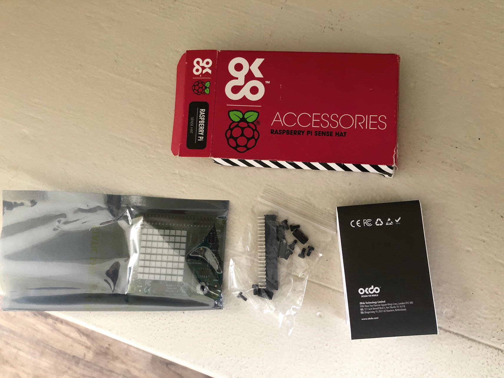
Shows the unboxing of our Sense HAT
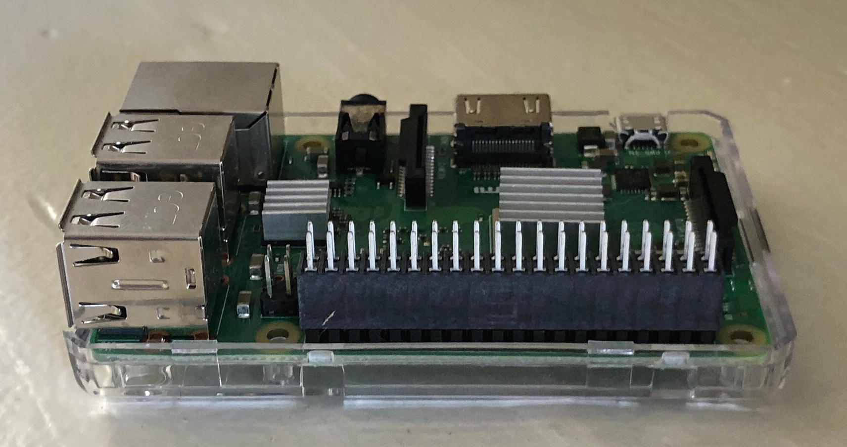
Board with the GPIO extender
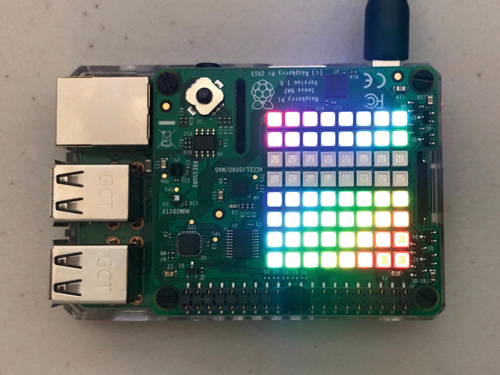
The board attached and started up
With the line uncommented, it will allow you to turn on the Pi without a display attached to it. Now you can attach the board and turn it on; it will light up all the LEDs each time and then turn off. If you haven’t altered the preceding config, you will need to attach an HDMI monitor or the lights will just stay on and it won’t finish the booting process. Once the LED goes off, it will be ready to log onto the board.
Sensors
Sensors and chipsets on the board
Name | Sensor | Address |
|---|---|---|
Accelerometer | LSM9DS1 | 0x1c(0x1e) |
Magnetometer | LSM9DS1 | 0x6a(0x6b) |
Pressure | LPS25H | 0x5c |
Humidity | HTS221 | 0x5f |
LED matrix | LED2472G | 0x46 |
The addresses are all documented on the Sense HAT found at https://pinout.xyz/pinout/sense_hat. It’s a good overview if you want details of what the circuits are doing and where I got some of my information from.
Install i2c tools on the board
➀ Downloads package information for all configured sources needed or the next two steps may fail.
➁ Installs necessary libraries for communication with the Pi.
➂ Installs tools to debug communication between the Pi and the HAT.
Running i2cdetect on the board
You might notice a few things pop out if you remember the addresses we just went over. Notice the 6a and 5f; those are our magnetometer and humidity sensor, respectively. What we should also have is a 5c, but where 50 and c meet, you may have UU (I tried with three boards, and my Pi 3 was inconsistent and showing it). The UU indicates a busy used state. Just be aware, if you do see a UU, then you won’t be able to use that sensor for the temperature reading; that will become important when we do the temperature calculations to know which sensors we have available.
There are other debugging tools that help visualize your bus. “lsmod | grep i2c” will give you an output:
This tells you all the sensors there are available; in addition, you can run “sudo i2cdump 1 [address]” to query the state of individual settings on your device.
If you want more details on how the Sense HAT and Pi systems work, there are quite a bit of documentations out there; I just wanted you to get enough of an overview that the coding going forward you would know where certain features come from. For now though, we are going to move on to setting up interactions with the LED and the temperature sensors. The way we are going to perform these operations is by using a variety of crates to control the sensors and display and then writing small wrappers to them for our individual functions we need.
LED Display
Displays we will create on the Sense HAT
Name | Function | Description |
|---|---|---|
Blank | blank | Blank out the screen to clear it out after we have displayed any symbols or sequences. |
Question mark | question | A question mark to display in case of an error. |
Processing | processing | Run through a progress screen that shows sequential blocks, to be used while waiting for a response from another system. |
Symbols | display_symbol | Used to display an 8x8 LED “image” to the screen; this will be a predefined multi-color output. |
Text display | display | Will output a different set of text, one letter at a time with a predefined wait of 800 ms. |
Text scrolling | scroll_text | Also displays a set of text, but instead of shifting a whole letter at a time, this will scroll the text through. |
Adding sensehat-screen to our Pi application
We are also adding in the features for controlling the fonts and scrolling; these are both needed for our application in order to display static and scrolling text; in addition, the linux-framebuffer is how we are going to write to the LED. There are other features like rotate and clip that we aren’t using so I didn’t include them, but you can go to the site and add extra features to your individual application.
The screen crate is a self-contained module via the sensehat_screen::Screen struct. We will be wrapping this and implementing the methods we mentioned earlier to interact with the screen. The Screen itself is a high-level API that interacts with the linux-framebuffer. Screen will open to the framebuffer’s file descriptor in order to connect and write to the LED matrix. From there, it will just be writing our input. Input comes in the form of the FrameLine struct that contains raw bytes needed for the buffer. From there, the Screen will take the FrameLine information and write it to the LED matrix. We will be converting Unicode to bytes directly when we create our holiday pictures; in other situations, we will use wrappers provided by the crate that allow us to convert the text to raw bytes without us having to create our own font catalog.
Frames
The 8x8 LED display will display colors on each matrix in a 16-bit RGB565 color representation; this basically gives you the color pallet you had in your old Atari Lynx (yes, very old school reference) but obviously not as a tight of a pattern. We are going to send to the framebuffers an 8x8 set of RGB colors. How this translates though is not an actual dual array but as a u8 single array that divides the RGB color in half for each LED. Thus, you will have a 128-sized array of u8 types ([u8: 128]), which is 8 x 8 x 2. This gives you two bytes for each color and then defines each LED matrix possible. For our “images” like the pumpkin and Christmas tree and any other static display, we will set up the constants in a multi-line format, so visualizing it can be easier.
https://chrishewett.com/blog/true-rgb565-colour-picker/ – Allows you to adjust the red green and blue to get the color and the RGB56 code
https://trolsoft.ru/en/articles/rgb565-color-picker – Reverses it and allows you to input the RGB56 code and see the color for it
A constant for a Christmas tree, file is in led/mod.rs
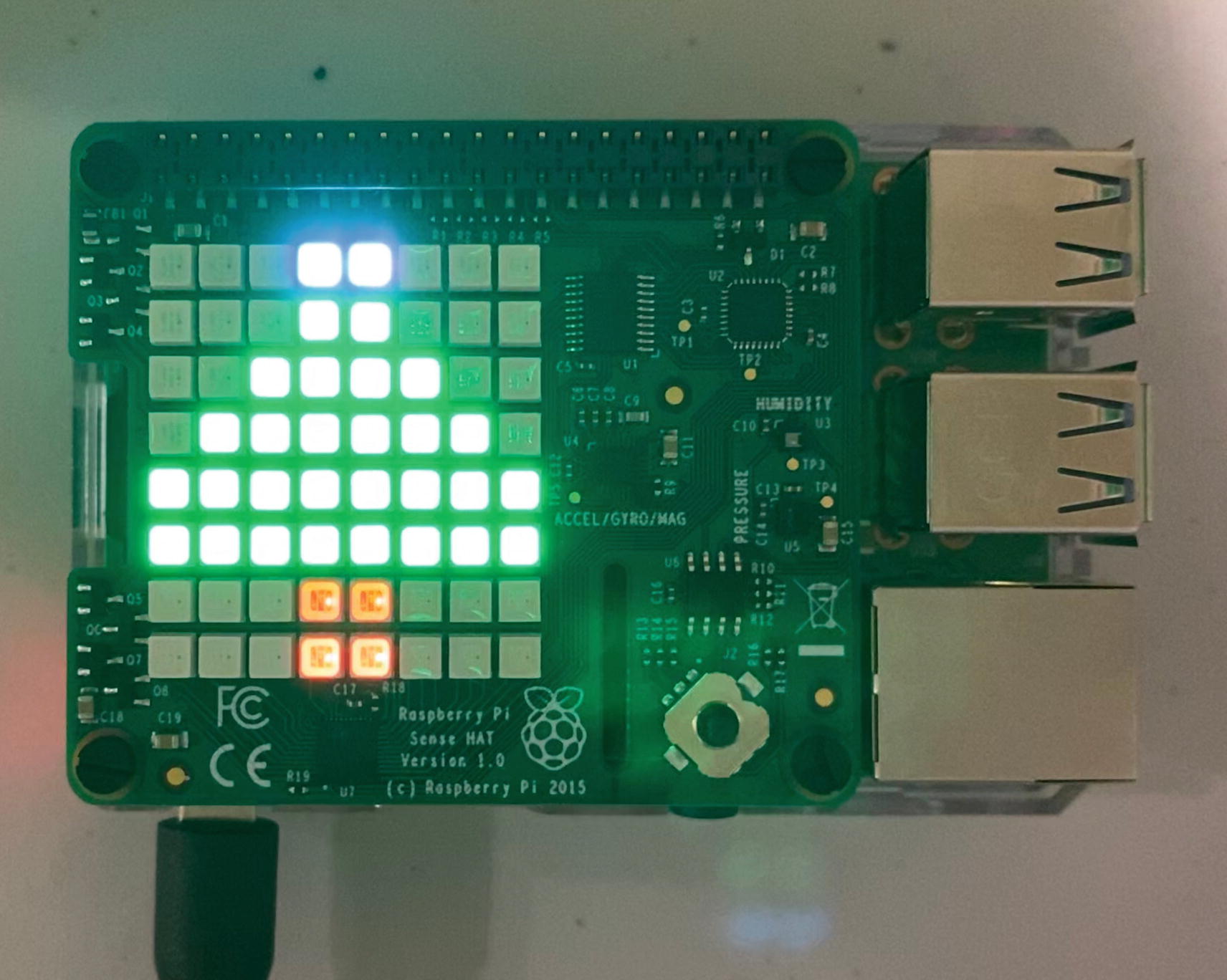
A Christmas tree being displayed on the Sense HAT
This is a black and white book, so the color variants may not show up here, but once you run the code on the board, it will. In addition, I’ve also added some yellow boxes we will use for concentric box display (for a processing image) and a pumpkin that we can use for the month of October. The code is in the repository; I have not included it here as I doubt any of you are going to line by line copy it.
Our set of yellow concentric squares
A question mark
An off frame which will be translated as a buffer of [0x00; 128] for our blank display
The code from the FrameProcessor ; file is in led/screen.rs
➀ Creates an array containing all the individual yellow squares.
➁ For use with the question mark, we want the display of it to be only 50% brightness.
➂ Initializes our new frame starting with the OFF frame from the slice we defined in led/mod.rs.
➃ The question mark uses font_to_frame from the sensehat_screen to convert the font to a FrameLine.
You will notice that this struct is not public, and it’s intended to be used only by the LedControls struct that we are creating next which will use these to send to the LED matrix.
LED Controls
Creating the struct for LedControls; file is in led/screen.rs
➀ Use all the structs from the crate that are needed by our application.
➁ The LED Path; this is the default path to talk to the file descriptor; this should be the same on your boards as well.
➂ Our struct has two properties that we need to instantiate before using.
➃ The Clone will be used later when having to pass through to our authentication modules.
➄ The implementation and creating of our LedControls.
Note using creating new FrameProcessor::new() on cloning is probably not the best idea since you could potentially have two different parts of an application writing to the screen at the same time and lead to a corrupted screen. However, on startup, the authentication is a blocking process and won’t allow any further functions till you log in, so this shouldn’t occur.
Two things really of note here: on bullet 5, if there is an error accessing the file descriptor, this will cause a panic. I haven’t wrapped it because if it does, then the rest of our app has a difficult time working since we will never be able to display the authentication or anything else to the screen. In addition, you will notice here we are implementing the Clone in bullet 4 as opposed to deriving it. The reason for this is Screen does not derive Clone so we would not be able to use the self-deriving macro. For our code, we are just going to open another connection to the file descriptor.
Next, we are going to add the individual functions that will produce output to the screen. I won’t be adding the code to test those here, as we are going to wait till we integrate it with the rest of the system, but feel free to run through testing each as we go along on your own Pi. We will be able to use the FrameLine instances we created earlier to pass to the screen to write them out. We use the call screen.write_frame passing in the FrameLine to it, which will write those frames to the LED. Let’s take a look at each method we are implementing; you will note they all follow the same general pattern.
Blank Screen
Blanks the screen; file is in led/screen.rs
Question Mark
Displays a question mark for 3 seconds; file is in led/screen.rs
Displaying an Image
Displays an array image for a given set of time before blanking out the screen; file is in led/screen.rs
Processing Screen
Processing display; file is in led/screen.rs
Display Text
Display a text string; file is in led/screen.rs
➀ Will take the text passed in and convert the set to a vector of FontUnicode.
➁ Now converts the Unicode to a byte array representation.
➂ Converts that byte array to a FrameLine that can be used to write to the LED.
Scroll Text
Function to scroll text across the screen; file is in led/screen.rs
➀ Create a vector of PixelFrame for each inner font of the text passed in with the colors for the font color and background image (black will be blank).
➁ Create the Scroll structure that will store the pixel frames for display.
➂ Finally display the text, scrolling in from left to right with a 250 ms delay between each.
You can scroll any direction from left to right, right to left, top to bottom, or bottom to top. Each has an appropriately named method.
All of these functions will provide us all our tools needed to interact with the screen in the rest of the application. I would suggest trying a few just to get the hang of it.
Temperature Display
For now, let’s move on to our sensor inputs. There are actually quite a few sensors on the board, and the crate we are using for this section has access to all the sensors. The gyroscope and accelerometer though didn’t really fit into a use case for the book, but you can investigate this crate later to learn how to gain access and use them. For this book, we are going to focus on getting a temperature reading. There are two temperature sensors on the board: one collocated with the pressure sensor and the other with the humidity sensor. You can use either sensor or you can use both and take the average between the two. We are just going to use the humidity sensor (I actually had issues with one of my SenseHats on the pressure sensor).
Adding sensehat-screen to our Pi application, in Cargo.toml
You will notice one of the feature flags is for humidity; I also added one for pressure that is available but not being used. Now earlier we talked about how we need to talk to the sensors in the i2c bus at specific addresses. This crate uses the i2cdev crate to do all the communication for us and get all the information needed from those sensors and wrap it in a nice usable struct. If you get curious, there is a htss221.rs module in the crate that has all the code and information on how to communicate with the i2cdev crate and how to read the bytes that the device is transmitting. The i2cdev crate is an easy-to-use crate to interact with if you know how you are trying to communicate. For example, if you wanted to interact with the humidity chip, we know from before that we are communicating to the /dev/i2c-1; since this is attached to the GPIO board, we also know from the documentation that it is on the address 0x5f; in order to instantiate the LinuxI2CDevice to communicate specifically with that chip, all you’d have to do is this:
i2cdev::linux::LinuxI2CDevice::new('/dev/i2c-1', 0x5f)
Determining the temperature from the humidity sensor
This will print out the temperature right now. You can go ahead and try it locally.
If you actually did it, you will notice the temperature seems a bit hotter than you expected. The reason for this is those sensors are RIGHT next to the board and other chips that are heating the air around our HAT sensors. This is picking up the heat dissipated by our Pi giving us a spurious reading. Now if you only care about registering drastic changes in temperature, then this is probably fine, and you can continue. However, if you want to try and get a more accurate temperature, there are a few things we can do.
First thing we can do is get a ribbon cable and move the SenseHat further away from the board; this will help produce a more accurate reading because it won’t be picking up any heat from the Pi’s CPU. However, this will look bad, and I don’t particularly like that solution.
- 1.
Get the temperature of the CPU which we can use to know how much the temperature of the sensor is being offset by.
- 2.
Apply a factor to it to try and determine the calibrated difference.
Essentially, we are going to have this equation to determine the real temperature:
temp_calibrated = temp - ((cpu_temp - temp)/FACTOR)
This will take the difference of the CPU minus the sensors’ temperature and divide it by a factor that will give us the amount to subtract. This factor is the tricky part; this is a calculated value based on the Pi’s reading and and actual thermometer’s reading. If you have the time and a real thermometer in the house, I’d take six or so readings during the day and apply them to that equation and average it to get the most accurate factor for your area. If instead you want a more average of a factor, the Weather Underground Pi project has done this already. We can use the factor they determined and generalize it to all. It won’t be as accurate since location and other factors are involved, but the number they came up with was 5.466 as the factor. Now this factor made it more accurate for me but was still not 100% accurate. But you at least get the idea of what we are trying to accomplish. If you want, run this and create your own factor to use.2
Creating our Atmospheric interactions ; file is in sensors/atmospheric.rs
➀ Set as a constant the location of the file containing the CPU temperature.
➁ Our only property is the SenseHat struct from the crate.
➂ Instantiate the struct; please note if you’ve added any features that sensor is marked as UU in our i2cdetect, this will fail.
➃ Retrieve the temperature from the humidity sensor in celsius.
➄ Retrieve the thermal temperature from the file.
➅ Convert the string temperature to a float.
➆ Apply our equation we went over earlier using the temperatures we just retrieved.
➇ Convert the temperature to fahrenheit because while I have two science degrees, I live in the United States.
➈ Format the value back to only have one digit, since the computed value has many decimal values.
If your sensors all work and want an even more accurate reading, you can take an average of the humidity and pressure sensors for the temperature as well. One thing to note is that the std::fs::read_to_string read is relatively fast and cheap, especially given the file is only one line, so we don’t need to worry about constant reads from the application. Also we are only going to be pulling the temperature sporadically. We will be using this code later for part of our daily schedule and with our joystick interactions.
Joystick Control
You may have not noticed it, but there is a little button on the top of the Sense HAT, closest to the Ethernet port; this is our joystick. The joystick can be moved left, right, top, or bottom, and there is even a center switch as well. Using the sensehat-stick crate (https://github.com/saibatizoku/sensehat-stick-rs) will allow us an easy interaction with the joystick. This crate allows us to detect the direction and the action performed on the joystick. We will only be doing some basic things with this crate for this chapter, but in later chapters, we are going to expand on this module.
Adding sensehat-stick-rs to our Pi application in our Cargo.toml
Simple example of interacting with the joystick
For each event, there is an action and a direction; the various directions are Enter-Up-Down-Left-Right.
And the various actions are Release-Press-Hold.
I think it’s fairly self-explanatory what each of these means. Go ahead and run the code in your application placing it as the last thing you do in the main and you can see some variety of the output it creates as you move the joystick around. We will be creating a joystick module later that will help with our interactions.
Creating Interactions
At this point, you should be able to interact with the various sensors on the Raspberry Pi, and hopefully you’ve run through a couple quick tests. This was the easy part, because running everything one time as a single call in Rust is straightforward. But now, we want to take everything we’ve done and combine it into a few interactions.
The commands we will be using for our first iteration of the pattern; file is in manager.rs
These commands will handle the two main use cases of displaying the temperature and printing out text or images to the screen. In the end, our consumer will receive the commands from the channel and perform actions on the LedControls and Atmospheric structs that we created earlier.
Daily – A module that runs at intervals to display the temperature at 8 a.m. and will display either a Christmas tree or a pumpkin at noon if it’s the Christmas or Halloween season.
Joystick – A module that will perform actions when we click in different directions. For this chapter, when you depress the center, it will display the temperature.
When all of this is put together, we will have a Pi board that can respond to commands happening in real time by the user and also be allowed to perform background routine operations all against the same modules. Giving us in essence multi-threaded multi-module access to singular components without violating any borrow checking or constantly creating new inputs to the sensors potentially causing deadlocks.
Tokio Async Run
We’ve used tokio in previous chapters mostly with the Rumqtt crate, but let’s dive into a bit more detail. The asynchronous processing has changed quite a bit with Rust in 2019, and tokio packages have been updated accordingly. If you used tokio in version 0.1, you had to do quite a bit of instantiating your runners directly and had to handle your process through promises and futures. Now with the async feature in the 1.39 version of Rust, we will be using polling instead of the promise/future route. Tokio 0.2 takes full use of the new async/await methods.
The async/await allows a developer to create a function asynchronously and then to await the return of the data and the finish of processing it. We will be using this to run our scheduler.
The tokio and futures crate dependencies, code in file Cargo.toml
Implementation of the tokio async code, code in file main.rs
➀ Uses the macro definition shortcuts creating a Builder::new with the default of a threaded_scheduler to start up our async processing.
➁ Creates the channel with an initialization of a 100 in the buffer.
➂ Since we cannot pass the transmitter to multiple modules, we need to clone it for each module we want to pass it to.
➃ Runs our daily background scripts transmitting commands when it hits a daily input.
➄ Awaits our joystick input, sending commands back based on the input.
➅ We wrap the LedControls and Atmospheric since they will be run asynchronously in the manager.
➆ Calls our manager that will await forever waiting for transmissions.
In that function, you have three calls we have not defined yet; let’s go ahead and define them.
Daily Runs
The main daily runner that will loop and run our special printouts, code in file daily.rs
➀ Get the local time; this is going to be used as a basis to know how long we are from the hour.
➁ Determine the amount of minutes till the top of the hour since we want to fire this at the top of the hour.
➂ Add that difference so now that time_at_hour will be the time of the next hour (i.e., if it’s 3:37, now this variable will be 4:00).
➃ Create our interval; the first parameter is the start, and the second is the interval; in this case, we check it every 60 minutes.
➄ Spawn a new thread for our asynchronous call.
➅ Run our initial call to print either a Christmas tree or pumpkin.
➆ This is the start of the infinite loop; this will await the first tick which occurs at the top of the hour.
➇ On the hour, it now runs the display.
➈ The send method used by other calling functions to send our Action to the receiver.
Few things to note here, the tx.send can only be called in an async functions which also means its parent has to be in an async function as well and so forth. This is why you are going to see a layer upon layer of async until you get to the tokio::spawn; from that point, the async addition to the function is no longer necessary. Also this send method will be in the other modules, but we aren’t going to print it out each time in the book.
We should also handle errors from the receiver better, but this code was already complicated enough as it is, but something for the reader to think about when using in a real-world application.
Checks if it’s Christmas or Halloween, code in file daily.rs
Our daily checker that gets ran hourly, code in file daily.rs
Checks if it’s October or if it’s December before the 26th, code in file daily.rs
This section shows us how to loop through a spawned function as well as how to create an interval and duration.
Joystick
Joystick responses, code in file joystick.rs
➀ Iterates through any events received.
➁ Checks for a temperature event; we will build this out more in future chapters.
Checks if the user wanted the temperature, code in file joystick.rs
We now have all the producers we are creating for this chapter; you have potentially three sets of producers sending data to the receiver to use.
Receiver
Our receiver await processing, code in file manager.rs
➀ Defines transmitter and receiver types of Action; this is used as a type shortcut in the other modules to know the type of transmitter being sent; it could be any struct or enum, but they have to be the same struct/enum for each channel.
➁ Awaits the receiver for transmitted data.
➂ Matches our Actions.
➃ Matches our Displays.
Processes each of the messages, code in file manager.rs
This section gives us the start to being able to expand functionality to the board as well as expand background processing that will be necessary when we add other modules to the Pi. Pis are powerful computers, so don’t be afraid to create a multi-threaded device so long as you keep all the memory and borrowing safeguards in place.
Logging In
We can now interact with the board devices, but we need to be able to interact more with all those endpoints we created in the first half that require a user. In order to interact with the services, we are going to have an authenticated user. The authenticated user will allow us to send a request token to the server to verify our users and verify they have access to box.
In Chapter 6, we went over the device authentication flow. In that chapter, we showed via curl commands and the web UI interactions how to perform a device flow authentication with Auth0. In this chapter, we are going to use those interactions into our code and integrate it into our Raspberry Pi application.
Yup OAuth 2
There are quite a few different authentication crates for Rust out there, and I looked through a few different ones. The yup-oauth2 is one of the more popular and has a solid diverse set of functionality in it. My main choice for picking it however is that none of the other crates had the necessary level of interaction that yup-oauth2 did for device flows. Remember, a device authentication flow calls to the server to get a code, returns that to the user, and then keeps checking back to the server to make sure the user has been authenticated. This was not the code I wanted to customize myself.
The only downside to yup-oauth2 is it seemed very much geared to the Google OAuth 2 Device Flow, which probably makes sense in terms of percentage of usage; however, that meant out of the box it did not work for our needs. Mainly there was one critical thing that needed to be customized, the name of the device_code sent; this field is not configurable, and we needed to configure them because Auth0 expects it to be device_code and Google just expects it to be code, different for Auth0. The code is hard-coded throughout yup-oauth2, so the only way to make this work was to branch this off. Once again, we will have to use a modified version; you can find that version at https://github.com/nusairat/yup-oauth2/. They are doing quite a few changes; in fact, from the time I started to write this chapter to finishing this book, the code changed drastically, and they are constantly improving the crate.
On startup of our application, the application will check for a valid JSON Web Token stored in the filesystem; if it exists and is valid, you will just proceed as normal and be considered logged in.
If the token does not exist, then call out to Auth0 to get a device code to use for authentication.
Display the device code on the LCD so that the end user knows what the device code they need to use is.
In the background, periodically check to see if the user has been authenticated.
Once authenticated, proceed to the next steps.
Luckily, most of this comes out of the box for us to use and will only require us configuring the application. For the authentication functionality we will create its own library. This will allow us greater reuse in terms of writing other apps that need authentication as well.
Since the authentication has to communicate directly with the LedControls and it’s now in its own library, this presents another problem but gives us a new learning experience; how do we have the LedControls we created in the previous section interact with the library? The solution is we will use traits that will configure how to display the logic, which in reality really is a better way since apps may want to write the output differently.
Let’s get this app started though. Since this application will not be part of the main Pi application, but instead will be a library referenced by it, let’s start by creating a library. We still use the cargo new like we normally do, but now we pass in a --lib flag which generates a lib.rs instead of a main.rs. In Listing 9-29, we generate this application.
Creating a rasp-auth library package
Creating a rasp-auth library package
This will include all the dependencies we need for this section; you will notice for the yup-auth2 I am referencing the git directory for my fork that has the necessary changes to support Auth0.
For our library, all the code we will be writing next will be contained in the lib.rs file. The code is not that long and it’s all performing a singular operation, so it did not make sense to add multiple modules.
Authentication Library
- 1.
Be a wrapper to run the authentication system so that we can minimize our code in the Pi app.
- 2.
Create a flow specifically to be used for Auth0 and a device flow procedure.
- 3.
Implement the use of a generic wrapper for display.
ApplicationSecret – This contains the endpoint for the authorization and auth orization URIs as well as any SSL certs and client IDs and secrets.
FlowDelegate – One of the traits we will be customizing. There is a more specific trait for our use, DeviceFlowDelegate. The delegate is used to help the OAuth system to determine what to do at each phase of the authentication flow. It controls the flow for the following events:
When user code is presented
Request code is expired
Pending
Denied
DeviceFlowAuthenticator – Builds our authenticator that will take in the DeviceFLowDelegate and also set where we plan to store the persisted token to.
The authentication method
➀ Used to define the VisualDisplay we are passing through (we will get to this more in a bit).
➁ Defines the ApplicationSecret as well as setting our URIs that are Auth0 specific.
➂ The FlowDelegate; here we are using a custom struct so that we can display the pin to the Sense HAT.
➃ Creates the authenticator which takes the flow delegate as well as the JSON location to persist to disk on a successful authentication and to be reused on refresh. This also takes in our grant_type that is specific to Auth0.
➄ The scopes we need to add to get all the tokens we need in the response; you may recall these are the same scopes we used in Chapter 6.
➅ Runs authentication of a user for the given scopes and with the configurations we created in step 4.
➆ Clears out our LCD display which may have had the device code displayed.
VisualDisplay – Will be our trait that defines the input
Access – Will be the struct that this function will be an implementation on.
VisualDisplay
The VisualDisplay trait
➀ Imports needed for this crate.
➁ JSON secret storage location; you can share this location between the apps running to be able to send authentication requests.
➂ The name of our project id that we defined in Auth0.
➃ Visual Display trait.
clear – To clear out the display, blanking the screen so that whatever output we have doesn’t stick around.
display_text – Displays any output text that we want to display. This can be the user code or an error response.
display_processing – Used to display an output saying the input is processing right now.
All of these cover all the use cases for displaying to the user the status via the LED display; this methodology of using a trait also allows us to add on to it as need be.
Entry Point Struct
The Access struct that is our public input into the application
The first three items are directly related to your individual Auth0 accounts, and you will need to plug in your own values when we instantiate the Access. The fourth, the output, is what is driving our input to the display device. Since we are performing multi-threaded access, we are also wrapping it in an Arc<Mutex<T>> call.
Defining the impl for the Access struct
➀ Defining the conditions the VisualDisplay will have to implement to be used in our application.
➁ The new function to create an Access struct.
The Send, Clone, and 'static are needed because the VisualDisplay is going to be used in various phases of the Auth life cycle, and they are required to by the future call, making use of the Send trait, and the flow delegate, which requires the Clone trait. This is a pretty standard procedure for Rust and allows us to enforce traits that need to be on the property that is being passed. In addition, the method we defined in Listing 9-31 will be part of this implementation.
At this point, you have almost all that is needed for authentication, one final set of code to implement for here, and that is to create our own flow delegate.
Auth0 FlowDelegate
- 1.
We need to overwrite the default settings to use Auth0-specific properties instead of Google-specific properties on the JSON authorization request.
- 2.
We want to customize the output of the device code to the LED display instead of just to the console log which is the default.
Defining the Auth0FlowDelegate
The implementation for Auth0FlowDelegate
➀ Defines that we are implementing Auth0FlowDelegate for the FlowDelegate trait.
➁ The clone is needed for any properties used in the FlowDelegate and that is why we need to add it to our VisualDisplay.
➂ Sends a call to display our user code to the LED display.
The present_user_code function on the Auth0FlowDelegate implementation
➀ Print out to the logger the user code and verification URL; this is to make easier for our debugging purposes.
➁ Get the output VisualDisplay that we passed in to the authorization. Here we unwrap and lock which is needed to get the object from Arc<Mutex<T>>.
➂ Output the device code to our LED display. This will give the user a visual representation of the device code they need to log in.
➃ Change the UI to display a “is processing” image that is repetitive.
In a perfect world, you’d probably repeat the code or add other queues or a way to repeat if necessary. I didn’t want to overly complicate the code so I will leave it to the reader to do that part. Our library is now complete; we can switch back to integrating this code into the Raspberry Pi application.
Raspberry Pi App Integration
Arguments used for the Authentication
Name | Short | Description |
|---|---|---|
auth_client_id | -i | Will store the client id for the Auth0 device flow we set up early. |
auth_client_secret | -t | Will store the client secret for Auth0. |
auth | -a | The URL for our Auth0 account; for my application, I set the default to rustfortheiot.auth0.com. |
Implement the LedVisualDisplay that is for our authentication; code is in main.rs
The run_authentication function that is in our main.rs of our Pi application
Summary
In this chapter, we greatly expanded the ability of our Pi device with the added Sense HAT hardware. We now have a device that can communicate securely with the backend as well as perform various local interactions. As we continue, we will make use of the authentication module to transmit and receive data.