

IBM Hyper Protect Virtual Servers on-premises installation
This chapter discusses IBM Hyper Protect Virtual Servers on-premises prerequisites and installation and includes the following topics:
6.1 Planning and prerequisites for Hyper Protect Virtual Servers on-premises
In this section, we discuss the requirements for Hyper Protect Virtual Servers on-premises (which is referred to as IBM Hyper Protect Virtual Servers) installation. For a basic installation, you need one Linux Management server and one Secure Service Container (SSC).
|
Note: For more information about IBM Hyper Protect Virtual Servers (previously known as Secure Service Container for IBM Cloud Private), see the following resources:
•Chapter 3: Secure Service Container installation and configuration of Implementation Guide for IBM Blockchain Platform for Multicloud, SG24-8458.
|
Table 6-1 lists the configuration parameters that are used for the Management Server.
Table 6-1 Configuration parameters for the Management Server
|
Parameter
|
Resource
|
Value
|
Example
|
Where to get
|
|
1
|
Architecture
|
x86 or s390x Linux
|
s390x
|
Cloud administrator
|
|
2
|
Host name
|
|
management_server
|
hostname
|
|
3
|
Primary Network interface Controller (NIC)
|
|
eth0
|
ifconfig -a
|
|
4
|
Management Server IP
|
|
10.152.151.100
|
ifconfig -a (inet addr parameter in the result)
|
|
5
|
Password for the user root
|
|
root_user_password
|
System administrator
|
|
6
|
Internal IP address
|
|
192.168.40.251
|
Network administrator
|
|
7
|
NIC for internal network
|
|
eth1
|
Network administrator
|
|
8
|
Subnet mask for internal IP
|
|
192.168.40.0/24
|
Network administrator
|
|
9
|
Gateway for internal IP
|
|
192.168.40.1
|
Network administrator
|
Table 6-2 lists the configuration parameters that are used for the SSC LPAR.
Table 6-2 Configuration parameters for the SSC LPAR
|
Parameter
|
Resource
|
Value
|
Example
|
Where to get
|
|
1
|
Partition IP address
|
|
10.152.151.105
|
System administrator
|
|
2
|
Master ID
|
|
ssc_master_user
|
System administrator
|
|
3
|
Master password
|
|
ssc_master_password
|
System administrator
|
|
4
|
Storage disks for quotagroups resizing
|
|
3600507630affc427000000000002000 (FCP) or 0.0.78CA (IBM FICON® DASD)
|
System administrator
|
The following minimum requirements must be met to deploy Hyper Protect Virtual Servers services:
•2 IFLs
•12 GB RAM
•190 GB storage (50 GB for the hosting appliance, 100 GB in the storage pool for one Hyper Protect Virtual Server container, and 40 GB for one Secure Build container)
Table 6-3 lists the configuration parameters that are used for the Secure Build Container server.
Table 6-3 Configuration parameters for the Secure Build Container server
|
Parameter
|
Resource
|
Value
|
Example
|
Where to get
|
|
1
|
Partition IP address
|
|
10.152.151.105
|
System administrator
|
|
2
|
Secure Build container name
|
|
securebuild1
|
Cloud administrator
|
|
3
|
CPU thread number
|
|
2
|
System administrator
|
|
4
|
Memory (GB)
|
|
12
|
System administrator
|
|
5
|
Storage for the Secure Build container application (GB)
|
|
10
|
System administrator
|
|
6
|
Storage for the Docker images built by Secure Build (GB)
|
|
16
|
System administrator
|
|
7
|
Storage for logs configuration data for the Secure Build Container (GB)
|
|
2
|
System administrator
|
|
8
|
Quotagroup of Secure Build container
|
|
myquotagroup
|
Cloud administrator
|
|
9
|
Connection method (port-mapping/IP)
|
|
IP
|
System administrator
|
|
10
|
Internal network name
|
|
encf900_internal_network1
|
Cloud administrator
|
|
11
|
Internal IP address (only needed if an internal network is used)
|
|
192.168.40.6
|
Cloud administrator
|
|
12
|
External IP address (only needed if an external network is used)
|
|
164.23.2.77
|
System administrator
|
|
13
|
Forward port for external (only needed if an external IP address is not assigned)
|
|
10433
|
System administrator
|
|
14
|
Repository ID of the Secure build container image
|
|
SecureDockerBuild
|
Cloud administrator
|
|
15
|
Tag of the Secure build container image
|
|
latest
|
Cloud administrator
|
|
16
|
Repository ID for your apps
|
|
MyDockerApp
|
Cloud administrator
|
|
17
|
Source code repository URL
|
|
github.com:MyOrg/my-docker-app.git
|
App developer or ISV
|
|
18
|
Source code branch
|
|
dev
|
App developer or ISV
|
|
19
|
Private key for Source code repository
|
|
|
App developer or ISV
|
|
20
|
Remote docker registry server
|
|
docker.io
|
Cloud administrator
|
|
21
|
Remote docker repository name for built images
|
|
docker_base_user/MyDockerApp
|
Cloud administrator
|
|
22
|
Remote docker registry user name to register the base images
|
|
docker_base_user
|
Cloud administrator
|
|
23
|
Remote docker registry user password to register the base images
|
|
passw0rd
|
Cloud administrator
|
|
24
|
Remote docker registry user name to push the images
|
|
docker_writable_user
|
Cloud administrator
|
|
25
|
Remote docker registry user password to push the images
|
|
passw0rd
|
Cloud administrator
|
|
26
|
Cloud Object Storage service API key (Optional)
|
|
0viPH...kliJ
|
Cloud administrator
|
|
27
|
Cloud Object Storage service bucket (Optional)
|
|
my-cos-bucket1
|
Cloud administrator
|
|
28
|
Cloud Object Storage service resource crn (Optional)
|
|
crn:v1...::1
|
Cloud administrator
|
|
29
|
Cloud Object Storage service auth_endpoint (Optional)
|
|
iam.cloud.ibm.com
|
Cloud administrator
|
|
30
|
Cloud Object Storage service end_point (Optional)
|
|
s3.....cloud
|
Cloud administrator
|
1 Because the internal network name is dynamically generated (depending on the customer’s hardware), this parameter might be different in your environment.
Table 6-4 lists the configuration parameters that are used to create repository definition files.
Table 6-4 Configuration parameters to create repository definition files
|
Parameter
|
Resource
|
Value
|
Example
|
Where to get
|
|
1
|
Repository name
|
|
docker.io/docker_base_user/MyDockerApp
|
Cloud administrator
|
|
2
|
Readonly Docker Hub user ID
|
|
docker_readonly_user
|
Cloud administrator
|
|
3
|
Docker Hub User password
|
|
docker_password
|
Cloud administrator
|
|
4
|
The public key
|
|
isv_user.pub
|
App developer or ISV
|
|
5
|
The private key
|
|
isv_user.private
|
App developer or ISV
|
Table 6-5 lists the configuration parameters that are used to create Hyper Protect Virtual Servers.
Table 6-5 Configuration parameters to create Hyper Protect Virtual Servers
|
Parameter
|
Resource
|
Value
|
Example
|
Where to get
|
|
1
|
Partition IP address
|
|
10.152.151.105
|
System administrator
|
|
2
|
External network name
|
|
encf900_network
|
Cloud administrator
|
|
3
|
Container external IP address
|
|
164.20.5.78
|
Cloud administrator
|
|
4
|
Internal network name
|
|
encf900_internal_network1
|
Cloud administrator
|
|
5
|
Internal IP address
|
|
192.168.40.188
|
Cloud administrator
|
|
6
|
Parent device
|
|
encf900
|
Appliance administrator
|
|
7
|
Gateway
|
|
192.168.40.1
|
Cloud administrator
|
|
8
|
Subnet
|
|
192.168.40.0/24
|
Cloud administrator
|
|
9
|
Repository name
|
|
MyDockerApp
|
Cloud administrator
|
|
10
|
Image tag
|
|
latest
|
Cloud administrator
|
|
11
|
CPU threads number
|
|
2
|
Cloud administrator
|
|
12
|
Memory size (GB)
|
|
12
|
Cloud administrator
|
|
13
|
Quotagroup size (GB)
|
|
100G
|
Cloud administrator
|
1 Because an internal network name is dynamically generated (depending upon the customer’s hardware), this parameter might be different in your environment.
Table 6-6 lists the configuration parameters that are used to create the Monitoring component.
Table 6-6 Configuration parameters to create the Monitoring component
|
Parameter
|
Resource
|
Value
|
Example
|
Where to get
|
|
1
|
Partition IP address
|
|
10.152.151.105
|
System administrator
|
|
2
|
Domain suffix
|
|
first
|
System administrator
|
|
3
|
DNS name
|
|
example.com
|
System administrator
|
|
4
|
Connection method (port-mapping/IP)
|
|
8443
|
System administrator
|
|
5
|
Private key for the monitoring infrastructure
|
|
server.key
|
openssl utility
|
|
6
|
Certificate for the monitoring infrastructure
|
|
server-certificate.pem
|
openssl utility
|
|
7
|
Certificates for the monitoring client
|
|
client-certificate.pem
|
openssl utility
|
Table 6-7 lists the configuration parameters to create and configure the GREP11 container.
Table 6-7 Configuration parameters to create and configure the GREP11 container
|
Parameter
|
Resource
|
Value
|
Example
|
Where to get
|
|
1
|
Partition IP address
|
|
10.152.151.105
|
System administrator
|
|
2
|
Crypto domain name
|
|
09.000b
|
System administrator
|
|
3
|
Domain suffix
|
|
grep11
|
System administrator
|
|
4
|
DNS name
|
|
example.com
|
System administrator
|
|
5
|
Connection method (port-mapping/IP)
|
|
IP
|
System administrator
|
|
6
|
Internal network name
|
|
my-private-network-name1
|
System administrator
|
|
7
|
IP address
|
|
192.168.10.106
|
System administrator
|
|
8
|
TLS key and certificate
|
|
key.pem, cert.pem
|
openssl utility
|
1 Because an internal network name is dynamically generated (depending on the customer’s hardware), this parameter might be different in your environment.
6.2 Networking for Hyper Protect Virtual Servers
IBM Hyper Protect Virtual Servers support Open Systems Adapter (OSA) for networking on IBM Z and LinuxONE servers that are configured for SSC LPAR. In addition, this OSA card can be virtualized when attached to SSC LPAR.
Networking in LPAR
The network interface is a software driver component of the operating system that uses OSA for networking. OSA supports the following types of network interfaces:
•Ethernet
This interface works with OSA in promiscuous mode and forwards all packets to and from the switch. Whenever any other LPAR broadcasts a packet for address resolution (ARP), that LPAR interacts with this interface type. As a result, the network can experience slow periods if many LPARs are connected to the same switch and running concurrent start and stop operations frequently.
•VLAN
This interface supports Ethernet packets that are tagged with a VLAN for network isolation. In addition, IP ranges might be reused by using a different VLAN ID.
•Bond
This interface can be used for fail-over scenarios. A bond interface might be connected to more than one OSA and if one OSA is not functioning, the bond interface steers network traffic to another OSA, which enables the fail-over scenario.
Figure 6-1 shows the network architecture.

Figure 6-1 Network architecture
6.2.1 Networking in Hosting Appliance (networking for Hyper Protect Virtual Servers containers)
Hyper Protect Virtual Servers is based on a Docker (runq) engine. Therefore, it often uses a Docker bridge interface to communicate between Hyper Protect Virtual Servers virtual machine images (VMs) and components that are outside of the LPAR. The Docker bridge interface can be created on top of a network interface of LPAR (Ethernet, VLAN, or Bond).
The following types of Docker bridge interfaces are available:
•Bridge
This type of Docker bridge interface is used when VMs want to communicate among themselves and VMs can access data that is outside of the LPAR through NAT. However, the problem with this type of networking is that we cannot communicate VMs from outside with the same network that VMs uses. To access the VM’s services, we must use a Port Address Translation (PAT) to access VMs from outside of the network by using the LPAR’s network (not directly by using the VM's network).
•macvlan
This type of Docker bridge interface is used to communicate with VMs in the LPAR from outside the LPAR by using the same network that the VM acquired. In this case, the VM’s MAC address is registered to the OSA and switch and it directly falls under the switch network.
Figure 6-2 shows the networking in Hosting Appliance.

Figure 6-2 Networking in Hosting Appliance
6.2.2 Creating an Ethernet interface
Complete the following steps to create an Ethernet interface:
1. In your SSC UI (https://<ssc_lpar_ip>), click the Networks section.

Figure 6-3 Network Connections window
A window opens in which you are prompted for the network information, as shown in Figure 6-4.

Figure 6-4 Entering network information
3. In the General tab, add the following information (see Figure 6-5 on page 153):
– Network Device: Add any device in the range that is allocated to your OSA. Start by entering the device number. The auto suggest shows the available devices. Select one available device (for example, 0.0.f709).
– Connection Name: Is automatically populated to enccw0.0.f709.
– Port: 0
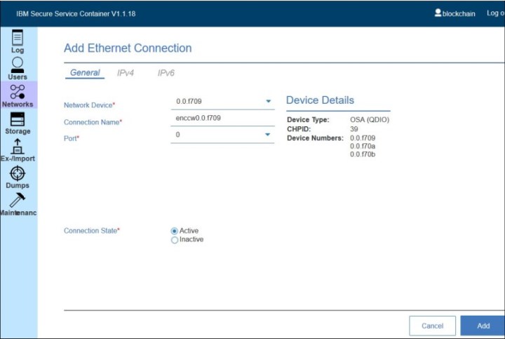
Figure 6-5 General tab information
4. In the IPV4 tab, make the following selections (see Figure 6-6 on page 154):
– Addresses: Manual
– Gateway: 192.168.40.1
– Address: 192.168.40.2
– Prefix: 24

Figure 6-6 IPv4 tab information

Figure 6-7 Clicking Add
A enccw0.0.f709 device is now added to the 192.168.40.0/24 network on which you can create your containers.
6.2.3 Creating a VLAN interface
Complete the following steps to create a VLAN interface:
1. In your SSC UI, click the Networks section.

Figure 6-8 Selecting VLAN
A window opens in which you are prompted to enter the network information, as shown in Figure 6-9.

Figure 6-9 Add VLAN Connection: General tab
3. To add a parent device, click the + icon. In the window that opens, add the network device that is provided by the OSA for VLAN (see Figure 6-10).

Figure 6-10 Adding the network device
4. Click Create. Now, the Parent device is available in the drop-down menu (see Figure 6-12 on page 159).

Figure 6-11 Parent device is available
5. Under the General tab (see Figure 6-12.), add the following information:
– Parent Device: Select the device that you added. In this case, encf300.
– VLAN ID: Add your VLAN ID; for example, 1121.
– Connection Name: Is automatically populated with vlan0f300.1121.
– VLAN Device: Is automatically populated with vlan0f300.1121.

Figure 6-12 Completing information in the General tab
– Address: Manual
– Gateway: 192.168.40.1
– Address: 192.168.40.2
– Prefix: 24

Figure 6-13 Completing information in the IPV4 tab

Figure 6-14 Clicking Add
Now you have a vlan0f300.1121 device added to 192.168.40.0/24 network on which you can create your containers.
6.3 Installation of Hyper Protect Virtual Servers components on-premises
In this section, we described how to install each component in the Hyper Protect Virtual Servers offering.
6.3.1 Preparing SSC LPAR for Hyper Protect Virtual Servers
To install Hyper Protect Virtual Servers components, complete the following steps:
1. Download the Hyper Protect Virtual Servers package from the IBM Passport Advantage® website. After it is downloaded, extract the contents of the build by using the following command:
tar -xvzf CC37UEN.tar.gz
The folders listed as shown in Figure 6-15.

Figure 6-15 Listed folders

Figure 6-16 Logging in to SSCC LPAR

Figure 6-17 Invoke Installer window
4. Export any active appliance configuration. Then, invoke the installer and accept the message to restart, as shown in Figure 6-18.

Figure 6-18 Confirming invoking the installer
A confirmation message is shown (see Figure 6-19).

Figure 6-19 Confirmation message
5. The Login window opens, as shown in Figure 6-20.

Figure 6-20 Login window
6. Log in again by using your user ID and password (see Figure 6-21).

Figure 6-21 Entering user ID and password
7. The installation window opens. Click the + button to select the SSC Hosting Appliance image (see Figure 6-22).
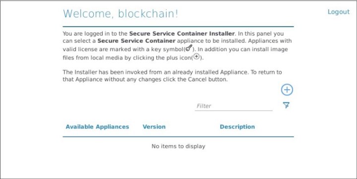
Figure 6-22 Welcome window

Figure 6-23 Selecting the SSCC Appliance image
9. Select the disk, as shown in Figure 6-24.

Figure 6-24 Selecting the disk
10. Confirm the appliance installation (see Figure 6-25).

Figure 6-25 Confirming the appliance
After a few minutes, the appliance is installed and is routed to the Login window, as shown in Figure 6-26.

Figure 6-26 Appliance is installed and routed to the Login window

Figure 6-27 Clicking Storage

Figure 6-28 Selecting LV Data Pool
13. Select the disks from the available devices (see Figure 6-29).

Figure 6-29 Selecting disks
14. Assign disks to pool (see Figure 6-30).

Figure 6-30 Assigning disks to pool
|
Important: Disks are formatted in this step.
|

Figure 6-31 Verifying disks
The disks are then formatted, as shown in Figure 6-32.

Figure 6-32 Disks are formatted
14. Verify that the status is correctly reflected (see Figure 6-33).

Figure 6-33 Verifying status

Figure 6-34 Selecting networks

Figure 6-35 Adding a network
17. Define the new network according to your network topology (see Figure 6-36).

Figure 6-36 Defining the network
21. Verify that the network is correctly displayed (see Figure 6-37).

Figure 6-37 Verifying that network is displayed correctly
The Hosting Appliance is now set up on the SSC LPAR.
6.3.2 Pushing the base images to the Docker repository
Complete the following steps to push the base images to the Docker repository:
1. After the Hosting Appliance image is installed (as described in 6.3.1, “Preparing SSC LPAR for Hyper Protect Virtual Servers” on page 161), load the CLI image on your Linux Management Server by using the following command:
docker load -i hpvs-cli-installer.docker-image.tar
The CLI docker images display after you run the docker images command, as shown in Figure 6-38.
|
Important: Two images are available. The image to be used depends upon the type of Linux Management Server that is used. The image with TAG containing 1.2.0.s390x must be used if the Linux Management Server is Z s390x architecture. If the Linux Management Server is a x86 machine, use the image with TAG shown as 1.2.0.
|

Figure 6-38 List of Docker images
Use the Hyper Protect Virtual Servers on-premises CLI Docker image as shown in Figure 6-38 based on the type of Linux Management Server architecture for the various CLI commands. The document shows the command samples for x86:
– x86:
ibmzcontainers/hpvs-cli-installer:1.2.0
– s390x:
ibmzcontainers/hpvs-cli-installer:1.2.0.s390x
2. Check that you enable Docker Content Trust (DCT) for your remote docker registry server by using the export DOCKER_CONTENT_TRUST=1 command.
3. The Hyper Protect Virtual Servers base images, which are part of this offering in your Docker hub, must be registered. Load the Hyper Protect Virtual Servers base images onto your Linux Management Server by completing the following steps:
a. Go to the hpvs-cli config directory and extract the base images into different folders, as shown in Example 6-1.
Example 6-1 Extract the base images into different folders
#cd /root/hpvs/VS/hpvs-cli/config
# mkdir HpvsopBase
# mkdir HpvsopBaseSSH
# tar -xvf HpvsopBase.tar.gz -C <destination-folder-HpvsopBase>
HpvsopBase.tar.gz.sig
HpvsopBase.py-rel.enc
# tar -xvf HpvsopBaseSSH.tar.gz -C <destination-folder-HpvsopBaseSSH>
HpvsopBaseSSH.tar.gz.sig
HpvsopBaseSSH.py-rel.enc
b. Create the Docker loadable binary under the same directory. The following warning message is displayed:
gpg: Can't check signature: No public key can be safely ignored when running the following gpg commands.
gpg <destination-folder-HpvsopBase>/HpvsopBase.tar.gz.sig
gpg <destination-folder-HpvsopBaseSSH>HpvsopBaseSSH.tar.gz.sig
c. Install the base images by using the following Docker load commands:
docker load -i <destination-folder-HpvsopBase>/HpvsopBase.tar.gz
docker load -i <destination-folder-HpvsopBaseSSH>/HpvsopBaseSSH.tar.gz
d. Run the docker images command to check whether the base images are loaded into the local registry successfully (see Figure 6-39).

Figure 6-39 docker images command
4. Register the base images in the Docker hub. Here, we use the SSH-enabled base image. In our example (per the Docker account), one private repository is available. Therefore, a private repository was created that is named redbooksuser1/hpvsop-base-ssh.
5. Use the docker tag command to tag the base images with the same ID that is used by the CLI tool. For example, 1.2.0 is the tag ID of the CLI tool that you can get by running the docker images command. Run the commands that are shown in Example 6-2 to tag both base images.
Example 6-2 Tagging both base images
docker tag ibmzcontainers/hpvsop-base-ssh:1.2.0-
abcedfg docker_base_user/hpvsop-base-ssh:1.2.0-
abcedfg
docker tag ibmzcontainers/hpvsop-base:1.2.0-
abcedfg docker_base_user/hpvsop-base:1.2.0-
abcedf
Figure 6-40 shows the output of the command.

Figure 6-40 Tagging the base images
6. Run the docker login docker.io command. Enter the Docker credentials for a successful login.
7. Push the base images to your remote docker repository by using the docker push command, as shown in the following example:
docker push redbooksuser1/hpvsop-base-ssh:1.2.0.-release-5c5f656
Figure 6-41 shows the output of this command.

Figure 6-41 Push the base images to your remote docker repository
Figure 6-42 shows the base image in the Docker repository.

Figure 6-42 Base image in the docker repository
6.3.3 Secure Build Container
Complete the following steps to create the Secure Build Container:
1. Load the SecureDockerBuild image on to your SSC LPAR by copying the image from securebuild-cli/config folder to hpvs-cli/config.
2. Load the SecureBuild image onto the LPAR by using the following command:
docker run --rm -it -v $(pwd):/hpvs-cli/config ibmzcontainers/hpvs-cli-installer:1.2.0 image load -i SecureDockerBuild.tar.gz --lpar [LPARNAMEORADDRESS]
3. After the image is loaded, you can check whether the image is loaded successfully by using the following command:
docker run --rm -it -v $(pwd):/hpvs-cli/config ibmzcontainers/hpvs-cli-installer:1.2.0 image list --lpar [LPARNAMEORADDRESS]
Figure 6-43 shows the output of the command.

Figure 6-43 Checking if the image is loaded successfully
4. Configure the hosts file and securebuild.yaml file under the securebuild-cli/config directory. For more information about networking, see 6.1, “Planning and prerequisites for Hyper Protect Virtual Servers on-premises” on page 144. A sample hosts file configuration is shown in Example 6-3.
Example 6-3 Sample hosts file configuration (only the first line of the RSA key is shown)
[lpars]
<lpar-ip> rest_user="<username>" rest_pass="<password>"
#For example:
10.20.30.40 rest_user="root" rest_pass="!W3Tx567@j"
A sample securebuild.yaml looks as below:
secure_build_workers:
- container:
port: '21442' #Port mapping for Securebuild Container
ipaddress: '<lpar-ip>'
name: '<name-for-securebuild-container>'
quotagroup_name: 'securebuild-qg'
imagetag: '<docker-image-version-for-secure-build>' #For ex: 1.2.0-release-hash
repoid: 'SecureDockerBuild'
delete_quotagroup_on_container_delete: 'true'
#20 GB Quota Group size
quotagroup_size: '20'
root_volume_size: '10'
docker_volume_size: '20'
data_volume_size: '10'
#cpu: '4' #Default 1
memory: '4098'
lpar:
ipaddress: '<lpar-ip>'
network:
name: 'bridge'
regfile:
id: '<your-docker-repo-name>'
github:
url: '[email protected]:<your-docker-username>/<your-docker-repo-name>.git'
branch: 'master'
#SSH Key registered with Github. Available in ~/.ssh/id_ras.pub.
#Note: Passphrase should not be set on the SSH key during generation.
key: |
-----BEGIN RSA PRIVATE KEY-----
YEDVKgIBAAKCAgEA1Y5ALt1iUnxC4ShAU0cmCiWWYcGPEgwogwNl2e0ceHDRhgLF .........
...........................................................................
-----END RSA PRIVATE KEY-----
docker:
repo: '<your-docker-username>/<your-docker-repo-name>'
image_tag_prefix: 'latest'
user: '<your-docker-username>'
password: '<your-docker-password>'
push_server: 'docker.io'
base_user: '<your-docker-username>'
base_password: '<your-docker-password>'
base_server: 'docker.io'
5. After configuring the hosts file and securebuild.yaml, create the securebuild container by using the following command:
docker run --rm -it -v $(pwd):/securebuild-cli/config ibmzcontainers/hpvs-cli-installer:1.2.0 securebuild create --name <secure-build-server-name>.
Figure 6-44 shows the output of this command.

Figure 6-44 Creating the securebuild container
6. The container is created successfully. Check the status of the container by using the following command:
docker run --rm -it -v $(pwd):/securebuild-cli/config ibmzcontainers/hpvs-cli-installer:1.2.0 securebuild status --name
<secure-build-server-name>
Figure 6-45 shows the output of this command.

Figure 6-45 Checking the status of the container
7. Update the Dockerfile of your application code to include the base image. Update the Dockerfile of your application code to ensure that the /usr/bin/initHPVSoP.sh script is part of the initialization code that is defined with the ENTRYPOINT clause.
The /usr/bin/initHPVSop.sh script must be invoked correctly to maintain the security and integrity of the Docker images that you are building. If the ENTRYPOINT clause is configured with your own script, you must include a call to /usr/bin/initHPVSop.sh in your own initialization processing.
The Dockerfile that is shown in Example 6-4 shows how to call the initialization code in the hpvsop-base parent Docker image. The initialization processing in the application Dockerfile is performed by the <yourscript.sh> script.
Example 6-4 Dockerfile example
FROM docker_base_user/hpvsop-base:1.2.0-release-abcdefg
COPY <yourscript>.sh /usr/bin
RUN chmod +x /usr/bin/<yourscript>.sh # Execute initialization code ENTRYPOINT ["/usr/bin/<yourscript>.sh"]
In the <yourscript>.sh initialization script, you must include a call to /usr/bin/initHPVSop.sh: ...source /usr/bin/initHPVSoP.sh...<Your initialization code>...
8. Commit the changes to your application code into the Git repository. Build your application code to a s390x compatible container image, and push it to your Docker Hub repository by using the following command:
docker run --rm -it -v $(pwd):/securebuild-cli/config ibmzcontainers/hpvs-cli-installer:1.2.0 securebuild build --name <secure-build-server-name>
The output of the command is shown in Figure 6-46.

Figure 6-46 Pushing the image to your Docker Hub repository
9. After the securedocker build command is completed, you can check the status of the container. If the Docker image is successfully built, it show the success message without any errors. If the build fails, the respective error message is shown (see Figure 6-47).

Figure 6-47 Build status
10. Verify whether the Docker image is built successfully by checking in the Docker hub (see Figure 6-48).

Figure 6-48 Verifying that the docker image is built successfully by checking in the Docker hub
The securebuild build command creates the following files for later use:
•An unsigned repository registration python file in the clear text, which you can use the credential and public key information when creating the repository definition file:
docker run --rm -it -v $(pwd):/securebuild-cli/config ibmzcontainers/hpvs-cli-installer:1.2.0 securebuild regfile --regfile-type full --name <secure-build-server-name>
•An unsigned repository registration JSON file in the clear text, which you can use as an input to the regfile encrypt command with a self-generated GPG key pair to create a signed and encrypted repository definition file.
Use the following command to retrieve this JSON file (see Figure 6-49 on page 183):
docker run --rm -it -v $(pwd):/securebuild-cli/config ibmzcontainers/hpvs-cli-installer:1.2.0 securebuild regfile --name <secure-build-server-name>

Figure 6-49 Retrieving the JSON file
•A signed manifest file for the application and the public key that is used for signing the manifest. Use the following command to retrieve the signed manifest file (see Figure 6-50):
docker run --rm -it -v $(pwd):/securebuild-cli/config ibmzcontainers/hpvs-cli-installer:1.2.0 securebuild manifest --name <secure-build-server-name>

Figure 6-50 Retrieving the signed manifest file
•The public key used to verify the signature on the manifest file. If you configured IBM Cloud Object Store (COS) to store your manifest files, the manifest file for each build is automatically pushed to COS after each build (see Figure 6-51 on page 184):
docker run --rm -it -v $(pwd):/securebuild-cli/config
ibmzcontainers/hpvs-cli-installer:1.21.0 securebuild public-key --name
<secure-build-server-name>

Figure 6-51 Manifest file pushed to COS after each build
6.3.4 Enabling monitoring on SSC LPAR
You can monitor various components by using the monitoring infrastructure that is provided by IBM Hyper Protect Virtual Servers.
|
Note: The monitoring metrics are collected from Secure Service Container partitions. Only Hyper Protect hosting appliance and Secure Service Container partition level metrics are supported for IBM Hyper Protect Virtual Servers v1.1.0.
|
This procedure is intended for users with the role cloud administrator.
Before you begin, ensure that the following prerequisites are met:
•The IP address of the Secure Service Container partition is available.
•Port 8443 is available for the monitoring infrastructure on the Secure Service Container partition.
•IBM Hyper Protect Virtual Servers CLI tools are installed on the x86 or Linux on IBM Z/LinuxONE (such as s390x architecture) management server.
For monitoring, the following containers are created:
•Monitoring
•Collectd-Host
Complete the following steps to configure monitoring on an SSC LPAR:
1. Under the monitoring-cli folder, create a hosts file with the connection information for the underlying RESTful API calls to the Secure Service Container partitions where the monitoring infrastructure is created. You can use the hosts.example file as the reference when configuring the hosts file.
2. Generate certificates for the secure communication between the Hyper Protect monitoring infrastructure (server) and the monitoring client. The monitor client invokes the collectd-exporter endpoint on the server to show the collected metrics.
|
Note: When you generate certificates, use collectdhost-<metric-dn-suffix>.<dns-name> or *.<dns-name> as the common name. A wildcard certificate with *.<dns-name> common name can be used across multiple partitions.
|
3. Create the ./config/monitoring.yaml file with the settings for your monitoring infrastructure. You can use the ./config/monitoring.yaml.example file as the reference when configuring the monitoring.yaml file.
4. After configuring the monitoring.yaml, create the Monitoring containers by using the following command (see Figure 6-52):
docker run --rm -it -v $(pwd):/monitoring-cli/config ibmzcontainers/hpvs-cli-installer:1.2.0 monitoring create

Figure 6-52 Creating the Monitoring containers
5. After the containers are successfully created, you can collect the metrics by using the wget command or by configuring any one of the tools that show the metrics in graphical manner (for example, Prometheus). We are the wget method to collect the metrics of the SSC LPAR, as shown in the following example:
wget https://collectdhost-first.bell.com:8443/metrics --ca-certificate=server-certificate.pem --certificate=client-certificate.pem --private-key=client-key.pem
Example 6-5 on page 186 shows the output of this command.
Example 6-5 wget command
[root@hurlnxa5:keys]# wget https://collectdhost-first.bell.com:8443/metrics --ca-certificate=mon-certificate.pem --certificate=prom-certificate.pem --private-key=prom-key.pem
--2020-03-16 10:12:57-- https://collectdhost-first.bell.com:8443/metrics
Resolving collectdhost-first.bell.com (collectdhost-first.bell.com)... 9.20.6.57
Connecting to collectdhost-first.bell.com (collectdhost-first.bell.com)|9.20.6.57|:8443... connected.
HTTP request sent, awaiting response... 200 OK
Length: 6929 (6.8K) [text/plain]
Saving to: 'metrics'
100%[======================================================================================>] 6,929 --.-K/s in 0s
2020-03-16 10:12:57 (49.8 MB/s) - 'metrics' saved [6929/6929]
6.3.5 Integrating with EP11 Library (GREP11)
You can create an EP11 over gRPC (GREP11) container on the Secure Service Container partition. Then, you can use the Hardware Security Module (HSM) to generate asymmetric (public and private) key pairs for signing or encrypting as needed by the deployed applications.
This procedure is intended for users with the role cloud administrator.
Before you begin, complete the following tasks:
•Check with your system administrator that the crypto express domain is configured in the EP11 mode.
•Check with your system administrator that the master key is initialized.
•Ensure that IBM Hyper Protect Virtual Servers CLI tools are installed on the x86 or Linux on IBM Z / LinuxONE (such as s390x architecture) management server.
To configure the GREP11 service for your Hyper Protect Virtual Servers container, create certificates that are used for secure communication. The certificates can be generated by using one-way TLS communication or mutual TLS communication. In our example, we use mutual TLS communication to generate certificates.
Complete the following steps to create the CA certificate for mutual authentication over TLS by using the golang-massl utility:
1. Install the cfssl toolkit by using the apt-get installation golang-cfssl command.
2. Generate the CA certificate and private key by using the golang-mass utility and the certificate from the trusted CA (see Figure 6-53).

Figure 6-53 golang-mass utility
3. Copy these certificates in grep11-cli/config directory as shown in the following examples:
– cp -p server.pem grep11-cli/config/
– cp -p server-key.pem grep11-cli/config/
– cp -p ca.pem grep11-cli/config/
4. After the certificates are generated successfully and configured in the grep11 directory, modify the hosts file by adding the SSC LPAR IP and the credentials. Then, get the crypto domain list on the HSM by using the crypto list command (see Figure 6-54 on page 188):
docker run --rm -it -v $(pwd):/grep11-cli/config ibmzcontainers/hpvs-cli-installer:1.1.0.s390x crypto list

Figure 6-54 Crypto list command
5. Update the grep11-config.yaml file for your GREP11 containers (for example, parameters crypto_domain name, IP, and certificates details).
|
Note: If you want the GREP11 container in your network of IBM Hyper Protect Virtual Servers and accessible internally, you must set the key network_name and IP to be part of your IBM Hyper Protect Virtual Servers network (the port always is 9876). The network_name can be created as VLAN or Ethernet type connection on the Secure Service Container partition.
|
6. After the grep11-config.yaml is configured, use the following command to create GREP11 container:
docker run --rm -it -v $(pwd):/grep11-cli/config ibmzcontainers/hpvs-cli-installer:1.1.0.s390x grep11 create
7. After the GREP11 container is created, check the status of the GREP11 container by using the following command (see Figure 6-55 on page 189):
docker run --rm -it -v $(pwd):/grep11-cli/config ibmzcontainers/hpvs-cli-installer:1.1.0.s390x grep11 status

Figure 6-55 Checking the status of the GREP11 container
8. After the GREP11 is created successfully, verify whether the application is configured correctly by using the GREP11 service.
9. The following Golang code examples show how to generate asymmetric (public and private) key pairs by using the GREP11 API, and assumes that more required Golang packages are included by way of import statements, such as the gRPC, http, and pb github.com/ibm-developer/ibm-cloud-hyperprotectcrypto/golang/grpc statement used by GREP11 to perform API function calls.
|
Note: You must use certificate-based authentication as shown in the following code examples to access the GREP11 container on the Secure Service Container partition.
|
10. For one-way TLS authentication, use the code snippet that is shown in Example 6-6.
Example 6-6 Code snippet
# The URL of GREP11 container in this example grep11.example.com:21876
const address = "grep11.example.com:21876"
# cert.pem is the same server certificate because it is one way TLS
var cert, _ = credentials.NewClientTLSFromFile("cert.pem", "")
var callOpts = []grpc.DialOption{
grpc.WithTransportCredentials(cert),
}
func Example_getMechanismInfo() {
conn, err := grpc.Dial(address, callOpts...)
if err != nil {
panic(fmt.Errorf("Could not connect to server: %s", err))
}
defer conn.Close()
cryptoClient := pb.NewCryptoClient(conn)
mechanismListRequest := &pb.GetMechanismListRequest{}
mechanismListResponse, err := cryptoClient.GetMechanismList(context.Background(), mechanismListRequest)
if err != nil {
panic(fmt.Errorf("Get mechanism list error: %s", err))
}
fmt.Printf("Got mechanism list:
%v ...
", mechanismListResponse.Mechs[:1])
mechanismInfoRequest := &pb.GetMechanismInfoRequest{
Mech: ep11.CKM_RSA_PKCS,
}
_, err = cryptoClient.GetMechanismInfo(context.Background(), mechanismInfoRequest)
if err != nil {
panic(fmt.Errorf("Get mechanism info error: %s", err))
}
}
8. For mutual TLS authentication, use the following code snippet.
# The URL of GREP11 container in this example grep11.example.com:21876
const address = "grep11.example.com:21876"
var (
# client certificate
crt = "client.pem"
# client private key
key = "client-key.pem"
# CA certificate
ca = "ca.pem"
)
var certificate, _ = tls.LoadX509KeyPair(crt, key)
var certPool = x509.NewCertPool()
var cacert, _ = ioutil.ReadFile(ca)
var a = certPool.AppendCertsFromPEM(cacert)
var creds = credentials.NewTLS(&tls.Config{
ServerName: address, // NOTE: this is required!
Certificates: []tls.Certificate{certificate},
RootCAs: certPool,
})
var callOpts = []grpc.DialOption{
grpc.WithTransportCredentials(creds),
}
func Example_getMechanismInfo() {
conn, err := grpc.Dial(address, grpc.WithTransportCredentials(creds))
if err != nil {
panic(fmt.Errorf("Could not connect to server: %s", err))
}
defer conn.Close()
cryptoClient := pb.NewCryptoClient(conn)
mechanismListRequest := &pb.GetMechanismListRequest{}
mechanismListResponse, err := cryptoClient.GetMechanismList(context.Background(), mechanismListRequest)
if err != nil {
panic(fmt.Errorf("Get mechanism list error: %s", err))
}
fmt.Printf("Got mechanism list:
%v ...
", mechanismListResponse.Mechs[:1])
mechanismInfoRequest := &pb.GetMechanismInfoRequest{
Mech: ep11.CKM_RSA_PKCS,
}
_, err = cryptoClient.GetMechanismInfo(context.Background(), mechanismInfoRequest)
if err != nil {
panic(fmt.Errorf("Get mechanism info error: %s", err))
}
}
6.4 Public Cloud service instantiation
The Hyper Protect Virtual Server service is also available on the IBM Cloud. This section describes the steps that are used to instantiate a virtual server
Deploying an instance
Complete the following steps to deploy an instance:
1. In the IBM Cloud, open the Hyper Protect Virtual Server service in the catalog.
2. Select and enter the required parameters, including deployed region, instance name, and ssh public key, as shown in Figure 6-56 on page 192. Then, click Create to create an instance.

Figure 6-56 Deploying a Hyper Protect Virtual Server instance in IBM Cloud
3. Check the instance status in the Resource list page, as shown in Figure 6-57. The deployment process takes several minutes to complete. After the process is done, the status shows as: provisioned.

Figure 6-57 IBM Cloud Hyper Protect Virtual Server instance status
Viewing the instance details
After the instance is provisioned, you can open the instance to see the details, as shown in Figure 6-58.

Figure 6-58 IBM Cloud Hyper Protect Virtual Server instance
Accessing your virtual server
You can get the virtual server’s public and internal IP addresses from the instance details page and access the virtual server by way of SSH, as shown in Example 6-7.
Example 6-7 Accessing the Hyper Protect Virtual Server instance
# ssh -i redbook [email protected]
The authenticity of host '169.63.212.8 (169.63.212.8)' can't be established.
ECDSA key fingerprint is SHA256:zsh2ZfgkfEX2n60DANflQFM7zOYQj9IZZfMS9iK+E28.
ECDSA key fingerprint is MD5:25:33:b9:cf:e2:e6:d3:31:47:9f:f7:36:66:48:8d:49.
Are you sure you want to continue connecting (yes/no)? yes
Warning: Permanently added '169.63.212.8' (ECDSA) to the list of known hosts.
Unauthorized access to this machine is prohibited.
Welcome to Ubuntu 18.04.3 LTS (GNU/Linux 4.15.0-62-generic s390x)
* Documentation: https://help.ubuntu.com
* Management: https://landscape.canonical.com
* Support: https://ubuntu.com/advantage
The programs included with the Ubuntu system are free software;
the exact distribution terms for each program are described in the
individual files in /usr/share/doc/*/copyright.
Ubuntu comes with ABSOLUTELY NO WARRANTY, to the extent permitted by
applicable law.
Unauthorized access to this machine is prohibited.
root@57c931651964:~#
..................Content has been hidden....................
You can't read the all page of ebook, please click here login for view all page.