
Chapter 4. Circuit Breaking
Circuit breaking is a foundation pattern designed to remove endpoints that persistently return error messages from a load-balanced group. Circuit Breakers go hand in hand with the retry pattern; while a retry attempts to recover from an endpoint returning an error when the system knows an endpoint is failing, a circuit breaker ensures that it is no longer called.
Problem
Let’s take a look at a theoretical problem in action. Ishank works on the Checkout API team; a service that allows customers to pay for their baskets. To process the customer’s payments the Checkout API calls an upstream service Payments. Like all services in the application to handle fault tolerance, the Payments service is made up of multiple instances as shown in figure 17.1.
There is, however, a problem with the Payment service; during high traffic, an individual endpoint can become overloaded, it accepts the connection but hangs while waiting to process the request. Eventually, a failing instance will recover but the time it takes is proportional to the number of requests it is trying to handle. The smaller the queue of requests to process the faster it recovers.
The delay in the Payment service to respond, causes the Checkout API to delay its response to the customer and eventually the failure of the transaction. The implications of this simple failure are actually quite dramatic. Ishank can see from the data that only 50% of customers retry the transaction, 25% abandon the transaction before the Checkout returns and the other 25% never retry upon receiving an error message.
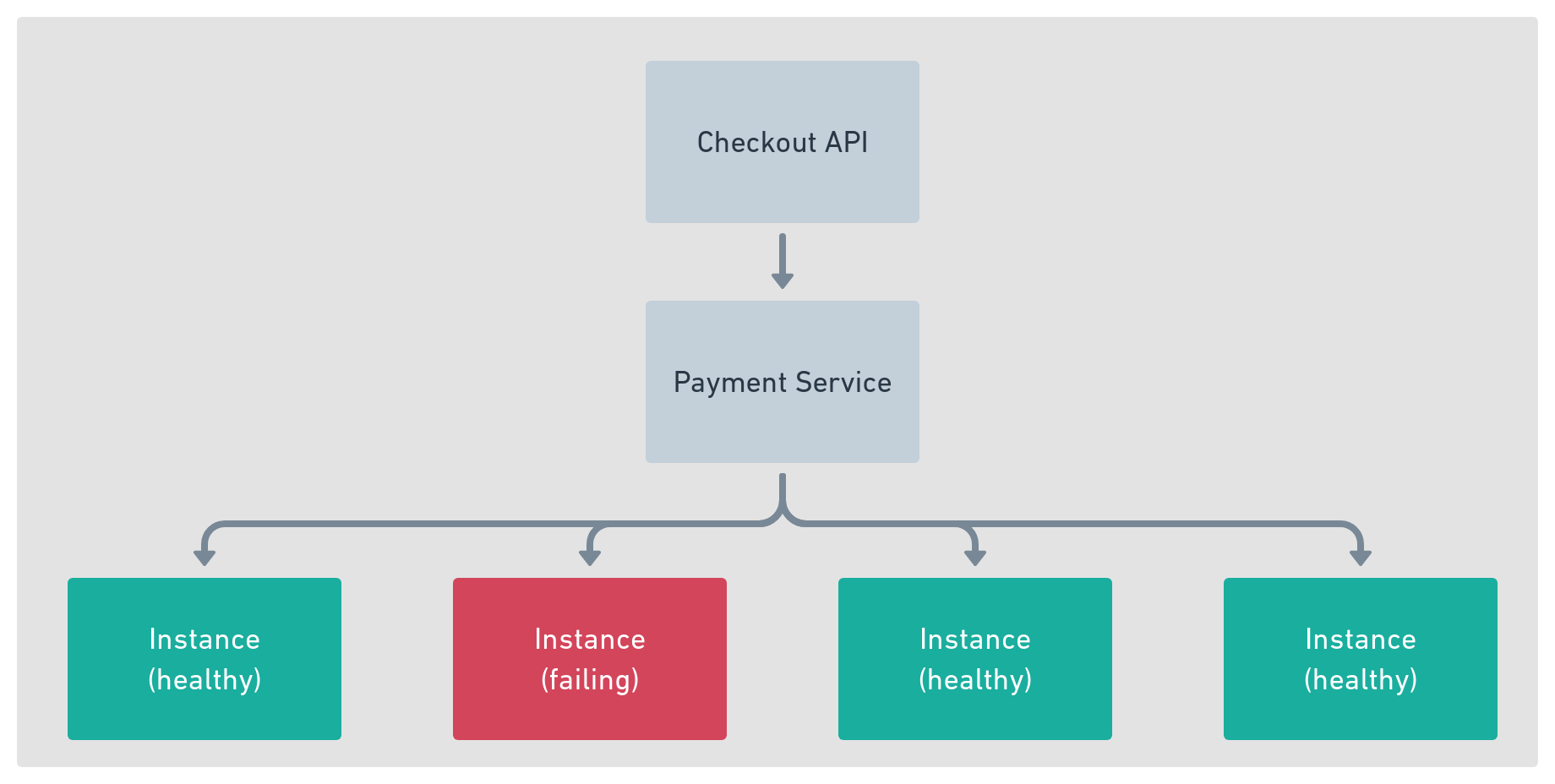
Figure 4-1. Checkout upstream services
The Payments service team is doing everything they can to help solve the problem but is also running into issues with the external banking provider. Requests to the Payments service are idempotent, meaning re-submitted requests are not a problem, to alleviate pressure, Ishank has implemented a retry when he receives a timeout from the Payments service. This retry attempts to send the payment request to another of the Payment service endpoints, which can process the request.
Ishank’s solution helps to alleviate the problem and reduce the number of customers abandoning their transactions, however, the persistent failure of one or more Payments endpoints means the user still needs to wait for both the first request to fail and the second to succeed. In addition, the continual traffic sent to a failing endpoint increases the time it takes to return to full health. It is also not just Ishank’s Checkout API that is affected, when the system is under high load, the delay in processing the requests causes a backup of work in other parts of the application reducing the overall capacity to process requests.
Within the service mesh, a service is a logical grouping of service instances that are able to satisfy a particular request. When making an upstream call the data plane selects one of these endpoints based on its load balancing algorithm and forwards the request. In almost all cases only healthy instances should form part of the load-balanced list, however, all of Ishank’s issues stem from the system’s inability to detect an unhealthy instance and to remove it from the load-balanced group.
The health of the service instances is generally determined through passive health checking (Chapter 10). With passive health checks, an endpoint on the service instance is called periodically and the result of this call is used to determine the inclusion or exclusion from the services load-balancing group. There are however two problems with passive health checks:
-
Since passive health checks are periodic, there is often a delay between a service becoming unhealthy and being removed from the load-balanced list. It is not uncommon to see health check intervals of 15s with the requirement for multiple failures before a service is removed.
-
Health check endpoints do not always report problems or latency in the service. For example, given a health check is configured to use the endpoint “/health”, if the service is experiencing latency due to waiting on a database table lock, and the health check is not codified to report this, then “/health” may not accurately report the health of the service. More often than not “/health” endpoints are configured to report that the service is simply running. Unless IO such as Memory, CPU, or Network are overloaded simple health endpoints do not report a service’s inability to handle the traffic.
The resulting delay in health reporting or incorrect health reporting is that the data plane’s load balancer sends requests to the unhealthy endpoint. There are three issues with this situation:
-
If the request has no retry configuration, the service returns an error to the client.
-
When a retry is configured, the end-user will be subject to a delay while the retry is in action.
-
If the upstream service is not responding due to load, continually calling the endpoint may not give it time to recover naturally.
In Ishank’s case, the Retry that he applied to requests to the Payment service went some of the ways to helping reduce abandoned transactions however it did not completely solve his problem. In addition, his Retries are actually increasing the load on the system that causes increased recovery time on the failing service instances.
A pattern that compliments the retry and timeouts and solves Ishank’s problems is the circuit breaker. Let’s see how it works.
Solution
The circuit breaker is application protocol-aware, it actively detects issues with an instance by examining the responses from the requests sent to it. In the instance that the circuit breaker detects an instance is failing, it temporarily removes it from the load balancer’s list of endpoints.
In its simplest form, a Circuit Breaker is configured with three parameters, the number of errors before an endpoint is removed and the duration it will be removed, and the criteria for failure, this can be the HTTP status code, gRPC status code, or the time taken to establish a connection or return a response.
In our hypothetical example, Ishank determines the parameters he will use to configure the circuit breaker by looking at his application metrics; he knows that consecutive failures of a single endpoint are almost always due to the service being overloaded, and that given time, the service will recover on its own.
However, he also understands that it is possible for sporadic errors to occur; this can be due to a flakey network or problems with the payment gateway. This type of error does not warrant the removal of an individual endpoint as there is no issue with the service as the problem is network-related. Using this information, Ishank decides that an endpoint should be removed after three consecutive failures. Typically it can take 60 seconds before a failing Payment endpoint returns to normal service. For this reason, he configures the Circuit Breaker to remove a Payments endpoint from the load-balanced list for 60 seconds.
This simple implementation protects the majority of Ishank’s users from unnecessary wait and protects the failing upstream from the additional load.
Technical Implementation
The service mesh data plane is responsible for circuit breaking, and the state is localized to each proxy. Detection and exclusion of an erroneous endpoint by one service proxy will not propagate this to the other proxies in the mesh.
The circuit breaker works by sitting in the request path as shown in figure 17.2, and it is always in any one of these three states:
-
Closed, the upstream endpoint is operating normally.
-
Open, errors to the upstream endpoint have exceeded the threshold.
-
Half Open, the circuit has been open for a set amount of time, and requests are sent to the upstream. A single failure will again fully open the circuit.
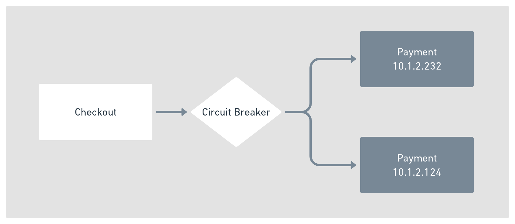
Figure 4-2. Circuit breaker flow diagram
Under normal operating conditions, the circuit breaker remains Closed, and requests are sent to the upstream as usual.
However, to protect against sending requests to an upstream when it is in an error state, you define an error threshold. The error threshold defines the maximum number of errors over a defined duration that is acceptable. When the threshold is exceeded, the circuit breaker Opens, and instead of calling the upstream, an error is returned immediately.
Once in the Open state, the circuit breaker assumes that the upstream failure is temporary and enters a recovery period. In contrast, in this state, any request to the upstream will immediately fail.
Once the recovery period elapses, then the circuit breaker enters a Half-Open state. When Half-Open requests are again allowed to be sent to the upstream, unlike the Closed state, when Half-Open no error threshold operates, a single error will fully open the circuit.
A more detailed view of this example can be seen in the flow diagram shown in Figure 17.3.

Figure 4-3. Circuit breaker flow diagram
Let’s see this in action by running an example application.
Reference Implementation
You can use Meshery to deploy a two-tier application consisting of a downstream service Currency with a single endpoint and an upstream service Payments with two endpoints, payments_v1 never returns an error, however, payments_v2 is configured to fail 100% of the time.
Load balancing between the active upstream endpoints is set to round-robin. If both endpoints are error-free, each upstream will receive 50% of the traffic. However, due to the configured error rates for the second endpoint and the configured circuit breaker, you will see only a handful of requests go to the second endpoint as the circuit breaker removes it from the load-balanced list.
deployment:
  circuit-breaking:
    upstream_services: 2
    upstream_error_rate:
      - 0%   # version 1  0% error rate
      - 100%  # version 2 100% error rate
    error_threshold: 2
    ejection_duration: 60s
This example uses the sample code from the source repository for this book in the circuit-breaking folder; inside this folder, you will find the file breaking_deployment.yaml. Let`s deploy the application using mesheryctl.
mesheryctl perf deploy --file ./breaking_deployment.yaml

## Deploying application
     Application deployed, you can access the application using the URL:
     http://localhost:8200
Now that the application has been deployed, you can run the performance tests. The test will run for 200 seconds at ten requests per second; this test aims not to stress the system but to test the action of the circuit breaker.
performance_test:
  duration: 200s
  rps: 10
  threads: 10
  success_conditions:
    - request_count["name=checkout"]:
        value: 2000
        tolerance: 0.01%
    - request_count["name=payments_v1, status=200"]:
        value: 1992
        tolerance: 0.01%
    - request_count["name=payments_v1, status!=200"]:
        value: 0
        tolerance: 0.01%
    - request_count["name=payments_v2, status=200"]:
        value: 0
    - request_count["name=payments_v2 status!=200"]:
        value: 8
        tolerance: 0.01%
Run this test using the following command:
mesheryctl perf run -file breaker_test.yaml
Once the test completes, you will see the summary report. The tests defined in the performance test document will all have passed, and you will see that the instance of the Payment upstream, configured to return an error 100% of the time, received very few requests as the circuit breaker did its job.
## Executing performance tests

Summary:
  Total:        200.01  secs
  Slowest:       0.032  secs
  Fastest:       0.016  secs
  Average:       0.020  secs
  Requests/sec: 10.01

  Total data:   2534390 bytes
  Size/request: 844 bytes

 Results:
  request_count["name=checkout"]                 2002 PASS
  request_count["name=payments_v1, status=200"]  1994 PASS
  request_count["name=payments_v1, status!=200"]    0 PASS
  request_count["name=payments_v2, status=200"]     0 PASS
  request_count["name=payments_v2 status!=200"]     8 PASS
If there wasn’t a circuit breaker between the Checkout and the Payment services, this example would have returned very different results. You would have seen a more even split between the two endpoints with approximately 1000 errors returned from the second instance. The circuit breaker has protected the system from making wasteful calls to a malfunctioning upstream.
Let’s take a look at some of the related patterns that work well with the Circuit Breaker.
Discussion
Like most of the patterns in this book, there are complementary patterns and caveats with their use. Let’s take a look at some of the related patterns.
Conclusion and Further Reading
In this chapter, you have learned the benefits and issues with the circuit breaking pattern, circuit breaking is one of the most common patterns that will be a core part of your toolbox when designing system reliability. To get the most out of the circuit breaking pattern we recommend you familiarize yourself with its related patterns, why not check out the further reading below.
-
Retry pattern - Chapter 19
-
Passive health checks - Chapter 10
-
Timeouts - Chapter 15