Chapter 6: A Best Friend for the Frontend
In Chapter 4, Trusting Facts and Eventual Consistency, we covered the event sourcing pattern and learned how it creates an outbound bulkhead that protects upstream services from downstream outages. In Chapter 5, Turning the Cloud into the Database, we covered the command query responsibility segregation (CQRS) pattern and learned how it creates an inbound bulkhead that protects downstream services from upstream outages. Together, these bulkheads fortify the boundaries of autonomous services and give teams the confidence to forge ahead with changes, knowing that these boundaries will help control the blast radius when things go wrong.
Now we'll turn our attention to the boundary service patterns that work at the periphery of the system. These autonomous services are responsible for catering to the kinds of changes driven by external actors, such as end users and external systems. In this chapter, we will focus on supporting end users. You will learn how to create backend for frontend services that are responsible for catering to the kinds of changes driven by the human actors who use the system. These services segregate the requirements of different actors so that they do not compete with each other and impede innovation.
In this chapter, we're going to cover the following main topics:
- Focusing on user activities
- Dissecting the Backend for Frontend (BFF) pattern
- Choosing between GraphQL and REST
- Implementing different kinds of BFF services
- Securing a BFF in depth
- Leveraging multiple regions
- Observing BFF metrics
- Optimizing BFF performance
Focusing on user activities
In Chapter 1, Architecting for Innovation, we saw that the role of architecture is to enable change so that teams can continuously experiment and uncover the best solutions for their users. We enable continuous change by defining fortified boundaries around things that change together so that we can control the scope and impact of any given change. The key to defining these boundaries is to understand the driving force behind change.
In Chapter 2, Defining Boundaries and Letting Go, we found that people (that is, actors) are the driving force behind change. We identified three autonomous service patterns that each cater to a different type of actor. In this chapter, we dig into the details of the Backend for Frontend (BFF) service pattern. The BFF service pattern works at the boundary of the system to support end users and the activities they perform.
Before going further, it is important to put the BFF service pattern in context, because it is easy to get bogged down in all the interrelated details when we build a complex system. There are many features, different users, integrations with external systems, and overarching business processes. We need to break the larger problem down into smaller problems so that we can control the complexity and manage change.
Our three autonomous service patterns control the complexity and the scope of change. We cover integrations and the External Service Gateway pattern in Chapter 7, Bridging Intersystem Gaps, and we cover business processes and the Control Service pattern in Chapter 8, Reacting to Events with More Events.
The purpose of the BFF service pattern is to focus on the requirements of end user activities and let all other concerns fade into the background. Concerns about integrations should not encumber a BFF service. Each user activity is a step in an overarching business process, but only the inputs and outputs of the step are of concern to a BFF service. This level of focus is important because it minimizes coupling and increases flexibility. Let's look at how the BFF service pattern facilitates change by zeroing in on user activities, self-sufficient teams, and autonomy.
A BFF service is responsible for a single user activity
The BFF service pattern facilitates change because each BFF service has a deliberate focus on a specific user activity and eliminates distractions and competing demands.
Following on from the Single-Responsibility Principle (SRP), a BFF service is responsible to one and only one human actor that interacts with the system's user interface. However, a single human actor may interact with a system in multiple ways to perform different activities. In this case, having one BFF service support multiple user activities could result in competing demands unless the activities are closely related.
In Chapter 3, Taming the Presentation Tier, we covered multiple approaches for breaking up a monolithic presentation tier, such as dynamically assembling many micro-apps in a micro frontends architecture or creating dedicated mobile applications for specific activities. In Chapter 5, Turning the Cloud into the Database, we discussed how data requirements change as data moves through its life cycle and interacts with different actors.
Taking all these considerations together, it is best to create a separate BFF service for each discrete user activity. This generally equates to creating a BFF service for each micro-app or mobile application, hence the term backend for frontend. For our food delivery example, we might include the following BFF services:
- A service used by restaurants to create menus, which is different from the service used by customers to browse menus
- A service used by customers to create orders, which is different from the service used by drivers to deliver orders and different still from the service used by customers to track the status of an order
- A service used by customers to view order history, another used by drivers to view delivery history, and yet another used by restaurants to view order statistics
- Separate services for customers, drivers, and restaurants to manage their accounts
Many of these examples seem very similar and their implementations may even look identical at first but avoid the temptation to merge them. They represent different actors and therefore different user activities. They are different bounded contexts. Before long, they will begin to diverge as the different actors drive different changes. Fortunately, as we covered in Chapter 2, Defining Boundaries and Letting Go, the services for the different actors will likely live in different autonomous subsystems, which will help ensure that the services remain separate.
Sometimes it is necessary to deliver the same user experience with multiple frontend implementations, such as a web application, a native iPhone application, and a native Android application. In this case, we need to make a decision regarding whether to support all the implementations with a single BFF service or one per implementation. If the functionality of all the implementations is identical, then a single BFF service is probably the right choice. If there are significant variations, then multiple BFF services may be better. If separate teams own the implementations, then that alone is a reason to have different BFF services, as we will cover next.
A BFF service is owned by the frontend team
The BFF service pattern facilitates change because the same team owns and implements the frontend and the backend.
This is a critical distinction. Traditionally, we have structured teams for the layers of the architecture with frontend teams, backend teams, and database teams. But this structure requires significant inter-team communication and coordination, which results in long lead times that impede innovation. Instead, self-sufficient, full-stack, autonomous teams own and focus on the frontend and the backend for one or more related user activities.
This enables a team to follow a UI-first approach. The team rapidly prototypes the user interfaces with no backend, to elicit fast feedback from the end user. In turn, the UI drives the requirements for the BFF service. This approach easily identifies the necessary queries and commands and eliminates the waste that arises when a separate backend team implements features that it assumes a frontend will need.
When a team is ready to implement a BFF service, they will typically leverage the same language used to implement the frontend, such as JavaScript. This allows the same developers to use the same tools to work on the frontend and the backend. This increases productivity because it reduces context switching as developers move between related frontend and backend tasks. As we will see in the Optimizing BFF performance section, this can also have a positive impact on runtime performance. In addition, the BFF pattern can reduce the cost of fielding a frontend team by controlling the number of necessary skill sets.
Decoupled, autonomous, and resilient
The BFF service pattern facilitates change because it eliminates inter-service dependencies.
This pattern is relatively new and has taken on various shapes and sizes as it has evolved. One common approach is to implement a BFF as a facade service that wraps and aggregates the calls to other services. But this approach is too brittle. It does eliminate the design-time coupling between the frontend and the various backend services, but it does not eliminate the runtime coupling. If any one of these other services has an outage, then the frontend user will also experience degraded functionality. Furthermore, inter-service coupling increases inter-team communication and coordination. A miscommunication between teams can lead to backward-incompatible changes that cause outages.
Instead, we implement our BFFs as autonomous services that eliminate synchronous inter-service dependencies. These services do not wrap other services. They own all the resources they need to continue operating when related services are down. They leverage the CQRS pattern to cache data from upstream services, as we covered in Chapter 5, Turning the Cloud into the Database, and they leverage the event sourcing pattern to produce events so that downstream services can react, as we covered in Chapter 4, Trusting Facts and Eventual Consistency. Together, these lower-level patterns provide the bulkheads that protect BFF services, so they can focus on delivering the responsiveness and resilience demanded by frontend users.
Let's take a look at the anatomy of a BFF service before we dive into some applications of the pattern.
Dissecting the Backend for Frontend (BFF) pattern
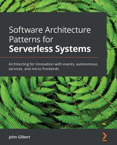
Creating a BFF service for each user activity does result in more services, so it is important that they all have a similar feel and structure. This will allow developers to easily work on different services. To help achieve this, it is a good practice to seed a new service with a skeleton from a standard template, stand it up, and then add the specific functionality. Figure 6.1 depicts the resources that make up the typical BFF service.
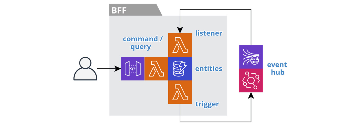
Figure 6.1 – Backend for Frontend pattern
The first thing to notice is that the typical BFF service provides a Trilateral API:
- It has a synchronous command and query interface that supports its frontend.
- It has an asynchronous listener interface that consumes domain events from upstream services via the event hub.
- It has an asynchronous trigger interface that produces domain events to the event hub for consumption by downstream services.
You can find a BFF service template here: https://github.com/jgilbert01/aws-lambda-stream/tree/master/templates. Let's dig into the different resources utilized by a BFF service.
Datastore
Each BFF service maintains its own highly available, fully managed datastore, such as AWS DynamoDB, S3, or Elasticsearch. This is how they achieve their autonomy. The datastore caches entities from upstream domain events, so the data is readily available to end users. Users make changes to the entities in the datastore, and the service produces domain events, in the background, to share the state changes.
It is important to understand that a BFF service stores data in a format that is most suitable for consumption by the frontend. This will produce a user experience that is more responsive and simplifies the frontend code by eliminating the need to continuously transform the data.
The following serverless.yml fragment, from the BFF service template, creates a DynamoDB table that supports the single table design best practice:
Resources:
EntitiesTable:
Type: AWS::DynamoDB::Table
Properties:
TableName: ${self:service}-${opt:stage}-entities
AttributeDefinitions:
...
KeySchema:
- AttributeName: pk
KeyType: HASH
- AttributeName: sk
KeyType: RANGE
GlobalSecondaryIndexes:
- IndexName: DataIndex
...
BillingMode: PAY_PER_REQUEST
StreamSpecification:
StreamViewType: NEW_AND_OLD_IMAGES
TimeToLiveSpecification:
AttributeName: ttl
Enabled: true
This standard table definition consists of generic KeySchema, which supports all entity types, and one or more global secondary indices. The CDC streaming and TTL features are enabled, along with on-demand billing.
We cover these database topics in detail in Chapter 5, Turning the Cloud into the Database.
API Gateway
The frontend must have access to the BFF service to perform queries and execute commands. The API Gateway provides this capability. It creates a secure and highly available perimeter around the functionality to support the frontend. We will cover this in detail in the Securing a BFF in depth, Leveraging multiple regions, and Optimizing BFF performance sections.
It is important to recognize that this interface supports a specific frontend and only that frontend. Other systems should not call this interface, as they are different actors. The External Service Gateway pattern fills this purpose, and we cover it in Chapter 7, Bridging Intersystem Gaps.
The following serverless.yml fragment, from the BFF service template, creates an API gateway and routes it to the functions that implement the queries and commands:
functions:
rest:
handler: src/rest/index.handle
events:
- http:
path: {proxy+}
method: any
cors: true
This example routes all HTTP methods and paths to a single function and enables Cross-Origin Resource Sharing (CORS) support. We cover this function next.
Query and command functions
The all-important job of a BFF service is to provide a human actor with the ability to execute a specific set of queries and/or commands. They retrieve requested data from the datastore, and they record the results of the user's activities, in the datastore. We implement this functionality in one or more functions, using the cloud provider's Function-as-a-Service (FaaS) feature, such as AWS Lambda.
A common question regarding FaaS is whether to use many fine-grained functions or fewer coarse-grained functions. Our user activity-focused BFF services are already fairly fine-grained, so I prefer to start with a single function that executes all the BFF's queries and commands. For a GraphQL-based service, this is a natural fit. For a REST-based service, I may eventually split out a separate function for queries and one for commands if the traffic volumes are different enough. But again, these variations may represent different user activities and warrant separate BFF services instead. As the number of queries and commands grows, this may also indicate that the scope of the BFF service has grown too broad.
We will dig deeper into these functions in the Models and connectors section and the Choosing between GraphQL and REST section.
Listener function
The listener function plays the crucial role in an autonomous service of implementing the CQRS pattern. It is a stream processor that consumes domain events from event-hub and materializes entities in the datastore for consumption by end users. BFF services store data in a format that is most suitable for consumption by the frontend, so it is the job of the listener function to transform the entities into the desired format.
This is a single function with the single purpose of materializing entities, but there are many different domain event types to process. The function leverages the pipeline feature of the stream processing framework to preserve the maintainability of the logic for the individual event types.
Listener functions are optional. If a BFF service does not need to react to domain events, then it does not need a listener function. However, most BFF services will have a listener function. It is only the BFF services at the very beginning of the data life cycle that may not need a listener function.
The following serverless.yml fragment, from the BFF service template, creates the listener function and configures it to consume from a stream in the event hub:
functions:
...
listener:
handler: src/listener/index.handle
events:
- stream:
type: kinesis
arn: ${cf:event-hub-${opt:stage}.streamArn}
...
We covered stream processing in general in Chapter 4, Trusting Facts and Eventual Consistency, and we covered the details of creating materialized views in Chapter 5, Turning the Cloud into the Database.
Trigger function
The trigger function fills the fundamental role in an autonomous service of implementing the database-first variation of the event sourcing pattern. It is a stream processor that consumes change events from the datastore's Change Data Capture (CDC) stream and publishes domain events to the event-hub for consumption by downstream services.
This is a single function with the single purpose of publishing domain events after a user executes a command, but there are many different change event types to process. The function leverages the pipeline feature of the stream processing framework to preserve the maintainability of the logic for the individual event types.
Trigger functions are optional. If a BFF service is read-only (that is, it has no commands), then it does not need a trigger function. BFF services that work towards the end of the data life cycle tend to be read-only. The datastore must also support CDC streams, otherwise, we need to use the stream-first variant of the event sourcing pattern to produce domain events.
The following serverless.yml fragment, from the BFF service template, creates the trigger function and configures it to consume from the datastore's CDC stream:
functions:
...
trigger:
handler: src/trigger/index.handle
events:
- stream:
type: dynamodb
arn:
Fn::GetAtt: [ EntitiesTable, StreamArn ]
...
We covered stream processing in general in Chapter 4, Trusting Facts and Eventual Consistency, and we covered the details of leveraging a datastore's CDC stream in Chapter 5, Turning the Cloud into the Database.
Models and connectors
In our effort to create architecture that enables change, we divide systems into autonomous subsystems, and we decompose those into autonomous services. The BFF service pattern provides a business logic tier to the presentation tier and these autonomous services own their own data tier. We can think of these building blocks as the macro-architecture that enables teams to work together across well-defined and fortified boundaries.
Now we need to turn our attention to the structure within each autonomous service and how it enables a single team to easily change an individual service. We have just seen how to decompose a BFF service into functions with well-defined responsibilities, such as queries, commands, listeners, and triggers. The software we write to run in these functions is not immense, but it can still become unwieldy if it is not well organized. We need to leverage some lightweight frameworks and put some simple layering in place. We can think of this as the micro-architecture within a service.
Akin to Alistair Cockburn's Hexagonal Architecture and Robert Martin's Clean Architecture, we want to isolate the business logic from the concerns of interacting with the technical resources, such as the datastore and event hub and the function execution environment. Therefore, we implement the business logic in Model classes and wrap all resource calls in Connector classes. Then we inject the connectors into the models using simple constructor-based injection. This does make the code more portable, but most importantly, it makes it more testable.
The following example shows the structure of a typical Model class:
export default class Model {
constructor( connector ) {
this.connector = connector;
}
save(id, input) { ... };
getBy(id) {
return this.connector.get(id);
};
queryBy(username) { ... };
submit(id) { ... };
delete(id) { ... };
}
export const toUpdateRequest = (uow) => ({ ... });
export const toDomainEvent = (uow) => ({ ... });
A BFF service works with a small slice of the system's overarching logical domain model. Each model class represents a separate domain aggregate used in the BFF service. Each method in a model, such as save, submit, and getBy, corresponds to a command or query provided by the service to the frontend.
A BFF service stores the domain entities in a format best suited for the frontend. The models provide mapper functions, such as toUpdateRequest and toDomainEvent, that transform the data between the internal and external data formats. These mapper functions support the listener and trigger functions, respectively.
A model class has a constructor for injecting connectors. The following example shows the structure of a typical Connector class:
class Connector {
constructor( tableName ) {
this.tableName = tableName;
this.db = new DynamoDB.DocumentClient({ ... });
}
get(id) {
const params = {
TableName: this.tableName,
KeyConditionExpression: '#pk = :id',
...
};
return this.db.query(params).promise()
.then((data) => data.Items);
}
update(Key, inputParams) { ... }
}
In this specific example, we see a connector that is wrapping the calls to AWS DynamoDB. The Model class dictates the signatures of the Connector intance's methods and the connector encapsulates all the details of interacting with the resource. This will allow the model to work with different connector implementations. For example, during the early stages of development, it may be helpful to implement a connector that holds data in memory, so that we can quickly experiment with the functionality. Then we plug in the real connector when we are more confident with the requirements.
The connectors also make it easier to write unit tests that execute in isolation, because it is easier to write mocks for connectors than it is to write mocks for resources. Developers only need to write a small set of connector unit tests that have the complexity of mocking the resources. Then, for the model unit tests, which account for the majority of test cases, it is only necessary to mock the connectors.
Each connector defines a constructor with configuration options. This provides a clean separation between the connector and the execution environment. For example, at runtime, a function will receive connection information in environment variables, whereas unit tests will simply assign test values.
Models and connectors are also agnostic to the execution environment. For example, we should be able to implement a BFF service using REST or GraphQL without having to change the model and connector classes. Now, let's take a look at using GraphQL versus REST and how these interact with the models and connectors.
Choosing between GraphQL and REST
GraphQL has become very popular in recent years, which raises the question of whether it is better to use REST or GraphQL. The short answer is that it depends on the user activity.
Does a user activity involve many users interacting with the same data or a few users interacting with different data? Taking our food delivery system as an example, a few employees from each restaurant will interact with just the menu of their restaurant, whereas many customers will interact with the menus of many restaurants. Furthermore, the customers are only reading the menus and the restaurant employees are editing the menus.
This means that we can use the cache-control header to improve the responsiveness of the system for customers and reduce the cost of the system. This is where REST excels. Representational State Transfer (REST) was designed to take full advantage of the infrastructure that makes up the internet, such as routers and content delivery networks. So, it makes sense to use REST for a customer-facing menu service.
GraphQL, on the other hand, uses the POST operation, so it is not well suited for read-only scenarios. But it is very well suited for more ad hoc activities where the user is navigating through and editing data, such as restaurant employees maintaining menus or customers maintaining their account information and user preferences.
In Chapter 7, Bridging Intersystem Gaps, we will cover the topic of webhooks, which usually require RESTful endpoints. We will also cover the topic of external interfaces, which traditionally expose a RESTful endpoint. These are akin to a BFF service, but they support an unbounded number of external systems. This means that versioning and backward compatibility are of utmost importance. Versioning is another area where GraphQL excels because clients declare the exact fields they need. This makes it easier to track how clients use the interface and craft backward-compatible changes.
The major advantage of GraphQL is that its client-driven query approach is less chatty than REST. A typical RESTful interface will require an application to make several calls to retrieve a full domain aggregate. This kind of lazy retrieval may be preferred if the user does not need the full object. GraphQL, on the other hand, lets the client specify the fields to return and the associations to traverse, which allows the client to retrieve more data all at once. This level of flexibility is less important for a highly focused BFF service, but it is very helpful for an external interface.
My general guideline is to use REST for customer-facing read-only services and GraphQL for everything else. Sometimes, it may be necessary to support both. Let's see how models and connectors help us do this.
REST
REST is the traditional choice for implementing services. As we have discussed, it is better for read-only services, webhooks, and external interfaces. The following code fragments implement the handler for the rest function we declared in the Dissecting the Backend for Frontend (BFF) pattern section:
const api = require('lambda-api')();
import Connector from '../connectors/dynamodb';
import Thing from '../models/thing';
const connector = new
Connector(process.env.ENTITY_TABLE_NAME);
api.app({
models: {
thing: new Thing(connector),
}
});
...
export const handle = async (req, ctx) =>
api.run(req, ctx);
The handler uses the lambda-api framework, which is very similar to Express, but with a significantly smaller footprint. It works with both AWS API Gateway and AWS Application Load Balancer and hides the differences. The handler function simply needs to wire the pieces together. First, we register the models with the framework and inject the connectors on startup, so that this logic does not need to be repeated for each request.
Next, we implement the route that will handle requests to retrieve Thing entities by their identifier:
api.get('/things/:id', (request, response) =>
request.namespace.models.thing.get(request.params.id)
.then((data) => response.status(200).json(data)));
The route function has access to the models through the request object. The model handles the business logic, and the connector interacts with the datastore. This means the route function only needs to implement the glue code to map the inputs from the request object to the model and map the output from the model to the response object.
Now let's take a look at how we can use the same model and connector in a GraphQL function.
GraphQL
GraphQL is becoming the preferred choice for implementing services. As we have discussed, it is better for more ad hoc user activities that include editing data. It also has benefits for versioning and backward compatibility, it can be more efficient, and it is self-documenting. Furthermore, it has great framework support for both the client side and the server side.
Here is an example of hooking up GraphQL in a Lambda function. The following serverless.yml fragment creates an API gateway for the service:
functions:
graphql:
handler: src/graphql/index.handle
events:
- http:
path: graphql
method: post
There is one route that directs POST requests for the graphql path to the function that implements a GraphQL schema. Next, we have a fragment of a GraphQL schema that defines the Thing domain entity and a query to retrieve Thing by ID:
type Thing {
id: String!
name: String
description: String
}
extend type Query {
thing(id: String!): Thing
}
This schema corresponds to the model class we defined in the Models and connectors section. There will typically be a one-to-one relationship between schema fragments like this one and model classes. We will see how resolvers bring the two together in a moment. Next, we implement the handler for the graphql function:
import { ApolloServer, gql } from 'apollo-server-lambda';
import schema from './schema';
import Connector from '../connectors/dynamodb';
import Thing from '../models/thing';
const connector = new
Connector(process.env.ENTITY_TABLE_NAME);
const handler = new ApolloServer({
...schema,
context: () => ({
models: {
thing: new Thing(connector),
},
}),
}).createHandler();
export const handle = (req, ctx, callback) =>
handler(req, ctx, callback);
The handler uses the Apollo framework to do the heavy lifting of processing GraphQL requests. The handler function simply needs to wire the pieces together. Once again, we register the models and inject the connectors on startup, so that this logic does not need to be repeated for each request. We also register the GraphQL schema. Finally, we implement the resolvers that map the schema to the models:
export default const resolvers = {
Query: {
thing(_, { id }, context) {
return context.models.thing.get(id);
},
...
},
Mutation: { ... },
};
In this case, we see the resolver that handles queries for Thing entities by their identifier. The resolver has access to the models through the context object. The model handles the business logic, and the connector interacts with the datastore. This means the resolver only needs to implement the glue code to map the inputs from the query to the model and return the output from the model.
These examples demonstrate how we can decouple the business logic from the execution environment. The business logic lives in the model classes and the connector classes encapsulate the external dependencies. Then we glue everything together in the execution environment with the appropriate framework. Now that we have seen some of the lower-level details, let's see how we can put all this to work in applications with some different kinds of BFF services.
Implementing different kinds of BFF services
Up to this point, we have learned how to control the scope of a BFF service and we have seen its major building blocks. In Chapter 5, Turning the Cloud into the Database, we discussed how different actors interact with data in different ways as it moves through its life cycle. Let's look at some different kinds of BFF services that cater to the different phases of the data life cycle. These include Task, Search, Action, Dashboard, Reporting, and Archive BFF services.
Task BFF services
A Task BFF service is a variation of the BFF service pattern that supports a step (that is, a task) in a larger business process.
Tasks are the workhorses of BFF services, as they constitute the majority of BFF services. A Task BFF provides a well-defined query to access the data the user needs to perform the specific task. It also provides the set of commands the user needs to accomplish the task, including a command to signal when the task is complete.
For example, from our food delivery system, the Delivery BFF allows drivers to acquire a delivery assignment, access the delivery information, and indicate when the delivery is complete. The Restaurant BFF provides agents with access to their assigned restaurants, so they can manage menus on behalf of restaurants. And the Account BFF allows customers to manage their locations and payment methods.
Figure 6.1 in the Dissecting the Backend for Frontend pattern section depicts the resources involved in a Task BFF service.
In its most basic form, a Task BFF may just provide Create, Read, Update and Delete (CRUD) capabilities. These tasks typically manage master data that support all the business processes. Or the task may sit at the beginning of the data life cycle where the user creates the domain data and then invokes a submit command to publish the domain event that initiates a business process.
A Task BFF may implement a step in a business process. In this case, the listener function of the Task BFF consumes domain events that initiate the tasks. It materializes the data so users can query their work. These domain events may come from control services that orchestrate the business processes or the individual services may choreograph the business processes themselves. We cover orchestration and choreography in Chapter 8, Reacting to Events with More Events.
The trigger function produces domain events to record the outcome of any intermediate commands. And it ultimately produces the domain event that signals the completion of a task and moves the larger business process forward.
Search BFF services
A Search BFF service is a variation of the BFF service pattern that provides read-only access to the data produced by one or more upstream services.
Whereas a Task BFF service provides its own well-defined queries, a Search BFF service helps users narrow in on what they are looking for. The users may not know exactly what they are looking for or even if the information exists. They may only have a general idea of what they want and be looking to see what is available.
For example, the Menu BFF service in our food delivery system provides the ability to search for restaurants and menu items by name, category, location, and more. The Restaurant BFF service allows restaurants to maintain their menus, but the Menu BFF search service provides the high performance and scalability needed to support millions of customers. In the back office, a search service would provide a central location for employees to search for all the business's domain information, such as customers and cases in a customer support system.
The following figure depicts the resources involved in a Search BFF service.
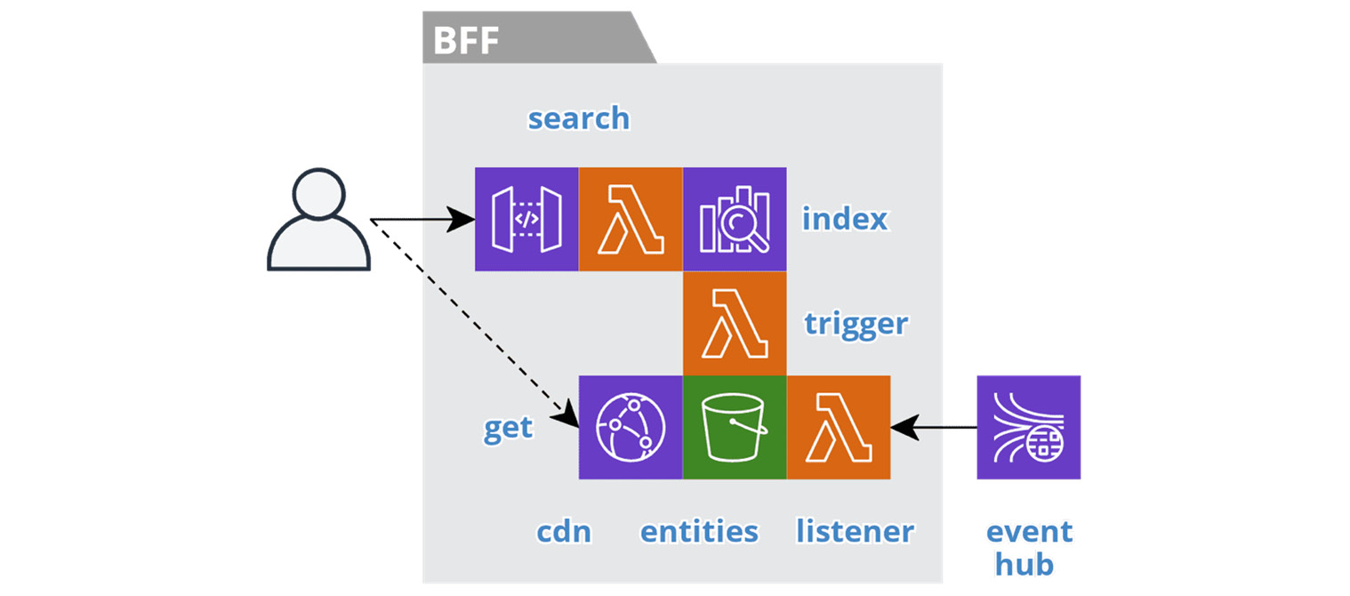
Figure 6.2 – Search BFF service
At the heart of a search service is an index, such as Elasticsearch. The search interface provides access to the index through an API gateway and a search function. Each search result contains summary information and the URL to access the detailed entity information.
The domain entities data is the perfect candidate for object storage, such as an AWS S3 bucket, because the volume of data is unbounded and it is read-only, reasonably static, and only accessed by the identifier. We store the data in the JSON format that we will return to the client, along with any images. The object keys should follow a good RESTful structure, such as /restaurants/123/menuitems/987.
For public information, like the Menu service, we serve the domain entities from the edge of the cloud using a Content Delivery Network (CDN), such as AWS CloudFront. We accomplish this by setting the cache-control property on the objects in storage so that we can cache the requests on the browser and the CDN. This provides the low latency and massive scale needed to support an unbounded number of customers. We discussed the origins of this approach in the Turning the database inside out section of Chapter 5, Turning the Cloud into the Database. For private data, such as a back-office search service, the client will access the data through a signed URL with a short time to live.
The listener function is responsible for materializing the entities and images in the S3 bucket. Then, the trigger function indexes the data, only after it is available in the bucket. Chaining these steps is important because each step is atomic, as we discussed in Chapter 4, Trusting Facts and Eventual Consistency. Splitting these steps ensures that the index will not return a result with a broken link.
Action BFF services
An Action BFF service is a variation of the BFF service pattern that performs a specific action in the context of another BFF service.
For example, the Menu BFF service in our food delivery system is a search BFF that supports browsing and navigating restaurants and menu items, but it does not support adding items to a cart. This is the job of an action BFF, such as a Cart service. This action BFF supports adding items to a cart, and stores the menu item's identifier, the quantity, and any configured options. Once the customer submits the order, the Cart service no longer needs to retain the cart information, because it is not editable, and the order-submitted domain event is a record of the state.
The following figure depicts the resources involved in an action BFF service.

Figure 6.3 – Action BFF service
An action service is responsible for performing a set of commands. We can think of these services as headless because they need other services to provide context for the inputs to a command. In other words, we pass all the necessary information into a command. They have no listener to create materialized views that the service can query to provide its own context. An action service may have a query to return the results of its own actions, but the service does not retain this information for any longer than necessary. Finally, a trigger function produces domain events to record the outcome of the commands.
Dashboard BFF services
A Dashboard BFF service is a variation of the BFF service pattern that provides users with a read-only, running tally of important domain values.
For example, a banking application will provide users with a dashboard of all their balances. In our food delivery system, restaurants can see statistics on how many customers viewed their menus, the top viewed items, and order statistics, so that they can gauge the value of using the food delivery service.
The following figure depicts the resources involved in a Dashboard BFF service:
Figure 6.4 – Dashboard BFF service
These example dashboard user activities have a well-defined access pattern. For example, each record contains a specific value, with pk set to the user's identifier or group, and sk set to the value identifier. The query simply returns the set of pre-calculated values for the current user.
These user activities are typically externally-facing and therefore require fast response times and high availability. These requirements, combined with the fact that the user experience is not ad hoc, mean that these services do not need and should not rely on complex analytics infrastructure.
Instead, a dashboard BFF service works with a control service that leverages ACID 2.0 transactions to perform the necessary calculations, as we cover in the Calculating event sourcing snapshots section in Chapter 8, Reacting to Events with More Events. The control service consumes lower-order domain events, calculates the current value, and produces a higher-order domain event, such as balance-updated.
This leaves the BFF service with the simple responsibility of delivering the read-only information to the user. The listener function consumes the higher-order events and materializes the values for the query to return. As the dashboard service is autonomous, it can always return the most recently received pre-calculated values.
Reporting BFF services
A Reporting BFF service is a variation of the BFF service pattern that provides users with a historical view of the data in the form of periodic reports.
In Chapter 5, Turning the Cloud into the Database, we learned how to control the volume of data and keep data lean in the individual services. Upstream services set a time to live on each record so that data expires when they no longer need it. However, it is common to have reporting requirements on historical data. This is a different user activity, for a different actor, in a later phase of the data life cycle. So, we create reporting services downstream for these activities.
The following figure depicts the resources involved in a Reporting BFF service:
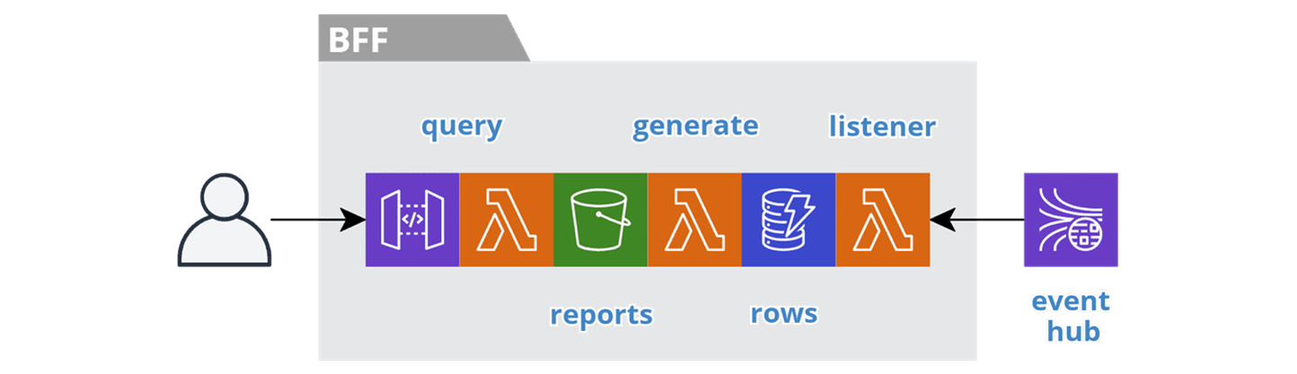
Figure 6.5 – Reporting BFF service
On a periodic basis, an actor expects to have access to reports, such as the monthly report on their area of responsibility. Traditionally, this data lives in a monolithic relational database and the users execute jobs to generate the reports and then wait for the jobs to complete. Instead, we can continuously prepare the reports so that they are ready at the desired frequency.
We organize, version, and store the generated reports in an S3 bucket with an appropriate key structure, such as /division/yyyy/mm/dd/report-name.pdf. The query interface allows the user to browse the reports.
The listener function consumes domain events and materializes the data in a table as rows formatted for a specific report. The pk field is set to the identifier of the report instance, which is equal to the S3 key and the sk field identifies the sorted rows in the report. The database stream triggers the generate function as we insert new rows. The function retrieves all the rows for the same pk value, produces the report, and stores it in the bucket.
At any time, the user can see the latest version of a report with the most recent data. The rows in the table have a time to live that is short enough to control the size of the table but long enough for late-arriving data to generate a new version of the report. We can retain the reports themselves indefinitely and age them into cold storage.
Archive BFF services
An Archive BFF service is a variation on the BFF service pattern that serves as the ultimate data collector at the end of the data life cycle. These services are governed by record management requirements that specify how long a company must retain various data.
In Chapter 5, Turning the Cloud into the Database, we learned about the importance of proactive archiving and how it enables services to keep data lean. Upstream services set a time to live on each record so that they delete data when they no longer need it. Downstream services collect the data they need and the cycle repeats. Archive BFF services allow all other services to remain lean.
The following figure depicts the resources involved in an Archive BFF service:

Figure 6.6 – Archiving service
Archive BFF services are proactive because they do not wait to collect data at the end of the life cycle. They continuously collect data from the moment users create it, so that upstream services can delete data freely.
The listener function consumes domain events and stores the data in an S3 bucket. This is akin to an event lake, but we organize the data around a specific domain entity identifier, such as customer, restaurant, or driver. A detailed history accumulates that we can use in the future for auditing and restoration. The query interface allows a user to browse the archive. The data ages in cold storage and we purge it after a regulated time period.
To put the archive service in context, we can use a case management system as an example. A Task BFF service is responsible for active cases. While a case is active, the index in the search BFF service points to the data in the task BFF service. When a case officer closes a case, the Task BFF service deletes the case data and we update the search index to point to the case data that has accumulated in the Archive BFF service. If we need to reopen a case, then we restore the case data from the archive to the Task BFF service and update the search index.
Each autonomous subsystem should have an archiving service for its domain aggregates so that its services remain lean. If a subsystem has many domain aggregates, then it may warrant multiple archives. As a whole, a system should have an archive subsystem at the end of the data life cycle that is responsible to the regulatory actor. This allows the other autonomous subsystems to remain lean.
Now let's turn our attention to securing our BFF services from top to bottom.
Securing a BFF in depth
BFF services are the most interesting to secure. They expose a synchronous interface to the frontend, which means they have the largest attack surface. Fortunately, securing a serverless BFF service in depth is mostly a declarative exercise. The following diagram enumerates the various resources a BFF service interacts with and the different security topics we must address, such as authentication, encryption in transit, least privilege, encryption at rest, and auditing.
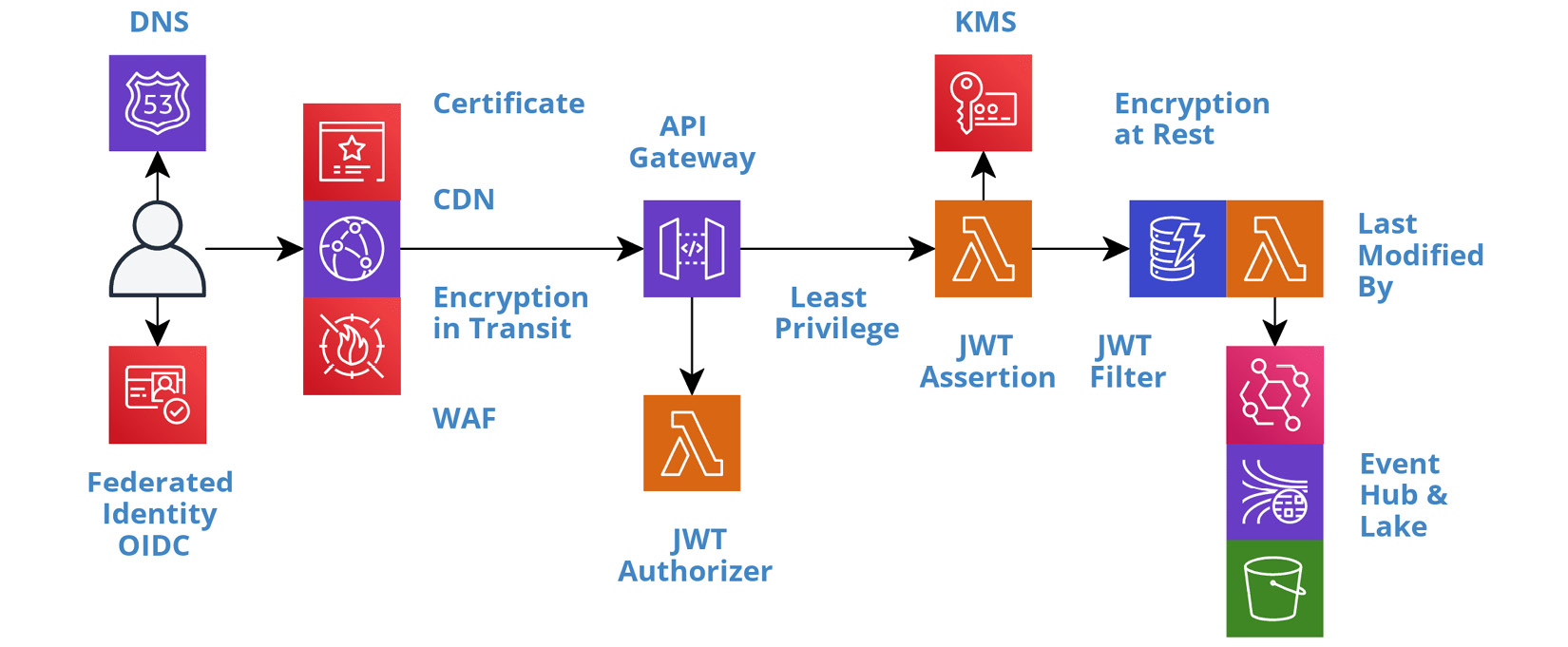
Figure 6.7 – Security in depth
Let's discuss these topics in the order that user activity will encounter them.
The perimeter
We need to take steps to secure the channel through which all requests to a BFF service will flow. Any BFF service that exposes a public interface outside of a private network, such as an AWS VPC, is vulnerable to Distributed Denial of Service (DDoS) attacks. This is a system-level concern that we addressed in Chapter 2, Defining Boundaries and Letting Go.
From the standpoint of an individual BFF service, the team must take advantage of these system-level capabilities. For example, each BFF service should have a CDN, such as AWS CloudFront, and associate it with the system-level Web Application Firewall (WAF) policies. The team should also be aware of and familiar with the continuous auditing and security monitoring that we perform at the system level.
Federated identity
Authentication is the first step for a private user activity. The frontend will initiate the authentication process with a federated identity provider, such as AWS Cognito, when the current user is unknown. We covered this process in detail in Chapter 3, Taming the Presentation Tier. The identity provider will implement the OpenID Connect (OIDC) protocol and the output of a successful login process is a JSON Web Token (JWT). The frontend retains the token and passes it as a bearer token, in the Authorization header field, on every request to a BFF service.
In transit
All calls to a BFF service must encrypt the data in transit. At a minimum, this is necessary to secure the JWT bearer token. A bearer token gives access to any bearer of the token, so we must not expose it in transit. We must encrypt all other sensitive data as well, so it is best to encrypt all calls.
Serverless services, such as AWS API Gateway, Lambda, and DynamoDB, require the use of HTTPS. Therefore, we only need to take steps to encrypt the calls to the CDN. This requires a custom SSL certificate. A cloud provider's certificate management service, such as AWS Certificate Manager (ACM), can create the certificate and automatically rotate it each year. Then we associate the certificate with the CDN and configure the CDN to require HTTPS.
JWT authorizer
Once a request reaches the BFF service, the first step is to authorize the request. This step is performed by the API gateway, so that we separate the technical concerns of handling the JWT token from the business logic. This also eliminates unnecessary calls to the query and command functions when the request is unauthorized.
The authorization process verifies the signature of the token and checks the expiration time, at a minimum. The process will usually validate the issuer and the intended audience as well.
Verifying the signature requires access to the key used to generate the token. A third-party provider will expose its public key, following the JSON Web Key Set (JWKS) standard, with a URL similar to https://my-identity-provider/.well-known/jwks.json. We configure the API gateway with this URL, so it can perform the verification.
Alternatively, we can implement a custom authorizer function that verifies the token. Authorizer functions provide the flexibility to verify custom and non-standard tokens, as well as standard tokens. Choosing between the alternatives depends on the needs of the token and the features of the API gateway service.
The following serverless.yml fragment, from the BFF service template, configures the rest function to use the authorizer function provided by AWS Cognito:
functions:
rest:
handler: src/rest/index.handle
events:
- http:
...
authorizer:
arn: arn:aws:cognito-idp:REGION:ACCOUNT:
userpool/ID
If the JWT token is valid, then the API gateway includes the claims in the request context when it forwards the request to the query and command functions. From here, we can perform JWT assertions and JWT filters as needed.
JWT assertion
So far, we have used a JWT to authorize access to a service as a whole. This may be all that is necessary for some services. For others, we may need to use the claims in the token to grant role-based authorization to the individual queries and commands in the service.
First, we need access to the claim that contains the user's assigned roles. The following code shows how to access the groups claim that AWS Cognito includes in its JWT token:
const getUserGroups = (request) => request
.requestContext.authorizer.claims['cognito:groups'];
Next, we need the code to assert that the user has the required role. The following middleware code asserts that the user is a member of a group with the required role name, before continuing. Otherwise, it returns a 401 HTTP status code in the response:
export const forRole = (roleName) => (req, res, next) => {
const groups = getUserGroups(req);
if (groups.includes(roleName)) {
return next();
} else {
res.error(401, 'Not Authorized');
}
}
Then we add the middleware to the individual routes and specify the required role name, such as forRole('Admin'):
api.get('/things', forRole('Admin'), getThings);
We can implement role-based assertions in GraphQL by decorating the model with directives, such as @hasRole:
extend type Query {
things(...): [Thing] @hasRole(role: 'Admin')
}
We can also implement fine-grained assertions in the model class, if need be. However, we should pass the claims to the model in a normalized format.
JWT filter
So far, we have used a JWT to authorize access to a service and used the claims in the token to assert role-based authorization to the queries and commands in the service. Now, we need to control access to the data at the record level. For example, customers should only have access to their own data, or employees should only have access to their team's data.
To accomplish record-level security, we need to carefully craft the queries that grant users access to the data. A request may explicitly include the data for these filters. However, we cannot trust these values, because they can be set to any arbitrary value by the caller.
Instead, we need to use the claims from the JWT to set the filter values. For example, the token will include the subject's identity and should include the roles and groups the subject is a member of. We can trust these values because we have asserted the authenticity of the token signature. In other words, the caller cannot tamper with the contents of the signed token. You should also assert the claims against the requested values to help find bugs or suspicious activity.
Last modified by
Auditing is another common security requirement. We need to track who changed what data and when. Our event-first architecture already provides auditing in the form of events and the event lake. We do not need to build another mechanism. We simply need to ensure that we produce all the right events and that they have all the necessary information.
In addition to domain events, the trigger function should produce lower-level data change events as users insert, update, and delete records in the entities datastore. We have already seen how to do this in the Leveraging change data capture section of Chapter 5, Turning the Cloud into the Database. This tells us what changed and when.
Now we need to know who invoked the command that changed the data. This information is available in the JWT. We need to pass this information down to the model class, so we can set a lastModifiedBy field on each record. The following code block provides an example of accessing the username from a JWT token in an AWS Lambda function:
const getUsername = event => event
.requestContext.authorizer.claims.['cognito:username'];
In the rest or graphql handler function, we use getUsername to pull the username from the claims and pass it to the constructor of the model class in a normalized format:
export default class Model {
constructor( connector, username ) {
this.username = username;
...
}
save(id, input) {
return this.connector.save(id, {
...input,
lastModifiedBy: this.username,
});
};
...
}
The methods in the model class assign the username to the lastModifiedBy field, so all the data change events record who performed the command. The event lake can now serve as an audit of all user activity. We can also use this information in a Reporting BFF service, as we covered in the Implementing different kinds of BFF services section, to make the audit information more accessible.
Least privilege
As always, we should assign permissions to the least privileges necessary. In addition to assigning permissions to users, we also have to assign permissions between resources. For example, we have to grant the API gateway permission to access the functions in a service and we have to grant the functions permission to access the datastore and the event hub.
The following serverless.yml fragment, from the BFF service template, grants the rest function permission to query and update the datastore:
iamRoleStatements:
- Effect: Allow
Action:
- dynamodb:Query
- dynamodb:UpdateItem
Resource:
Fn::GetAtt: [ EntitiesTable, Arn ]
The Serverless Framework will automatically generate any permissions it can implicitly infer from the specified metadata. For example, the API gateway will need permission to access the rest function, whereas we have to explicitly grant the permissions for the resources accessed within the function code. Do not use wildcards when granting permissions.
At rest
Encrypting data at rest is the last line of defense. If a hacker breaches all the other layers of security, the data will still be secure if we have properly redacted the sensitive information. We covered the details of encrypting data at rest in the Redacting sensitive data section of Chapter 5, Turning the Cloud into the Database.
The majority of data in a system originates from a BFF service. Therefore, it is crucial that we identify all the sensitive information used in a BFF service and ensure we redact it in the datastore and in the domain events. This will force all downstream services to follow suit because they will need to decrypt it before using it, which should make it obvious that they should re-encrypt it before saving it.
This means that the developers of a BFF service are the first line of defense. Fortunately, the cloud's shared responsibility model handles many of the lower-level security details, which frees developers to focus more time and effort on identifying all the sensitive information used within a BFF service and redacting it when we save and publish the data. In other words, security-by-design starts with the developers of BFF services. We need to know our domain models and take responsibility for redacting sensitive information.
Now let's turn our attention to running BFF services in multiple regions.
Leveraging multiple regions
Designing a system to run across multiple regions is a multifaceted problem and a running theme throughout this book. Each layer of the system plays its role. In Chapter 3, Taming the Presentation Tier, we saw how session consistency and offline-first mechanisms help the presentation layer ensure a seamless transition during a regional disruption. In Chapter 4, Trusting Facts and Eventual Consistency, we covered the implications of multi-regional deployments on stream processing and why we rely on replication at the datastore level, instead of replicating streams. In Chapter 5, Turning the Cloud into the Database, we covered the different strategies for data replication. And in Chapter 9, Choreographing Deployment and Delivery, we examine how to leverage multiple regions for canary deployments.
In this section, we cover how BFF services leverage multiple regions to provide users with a more responsive and resilient experience. Specifically, we look into latency-based routing, regional health checks, and regional failover.
Latency-based routing
Why should you run your system in multiple regions? It will require additional effort, but not much more effort, as we will see in Chapter 9, Choreographing Deployment and Delivery. And the benefits of regional failover may seem remote, until that day when you really need it.
The simple answer is, for your users' benefit. BFF services are user-facing services and responsiveness is important to users. More and more, users are spread across many geographic regions, whether they are your customers or fellow employees. This means that latency will be an issue for some of your users if the services are only running in a single region.
The following diagram depicts a BFF service running in two regions, east and west.
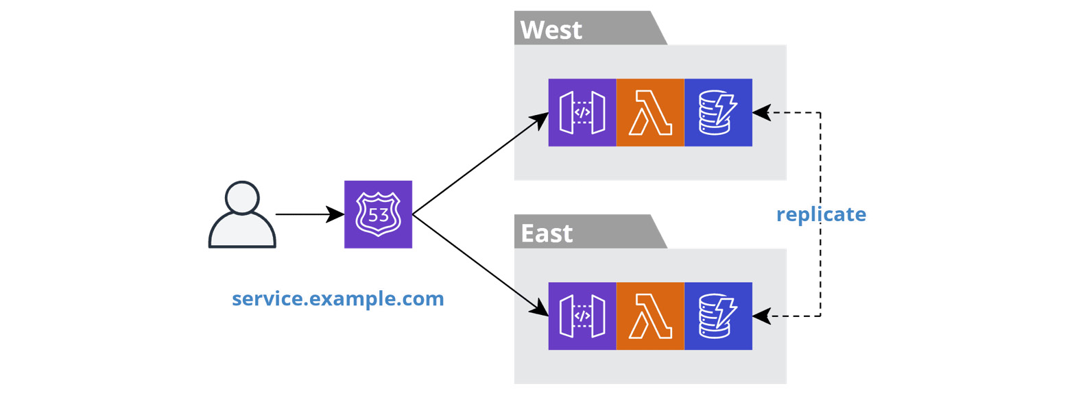
Figure 6.8 – Latency-based routing
We deploy a BFF service and all its resources twice, once in each region. This results in two separate and independent stacks. The stacks are only related with regard to data replication, as we covered in Chapter 5, Turning the Cloud into the Database, and because they share the same domain name.
When the frontend resolves the domain name, the cloud provider's Domain Name System (DNS) service, such as AWS Route 53, will return the IP address of one instance of the BFF service. There are many strategies for picking an instance. The latency-based strategy will pick the region that is closest to the location of the user.
The following serverless.yml fragment configures a BFF service for latency-based routing:
provider:
name: aws
endpointType: REGIONAL
...
Resources:
ApiRegionalDomainName:
Type: AWS::ApiGateway::DomainName
Properties:
DomainName: ${opt:stage}-${self:service}.
mysubsys.example.com
...
ApiRegionalBasePathMapping:
Type: AWS::ApiGateway::BasePathMapping
...
ApiRegionalEndpointRecord:
Type: AWS::Route53::RecordSet
Properties:
HostedZoneId: ${cf:global-resources-${opt.stage}
.hostedZoneId}
Name: ${opt:stage}-${self:service}
.mysubsys.example.com
Region: ${opt:region}
SetIdentifier: ${opt:region}
Type: A
AliasTarget:
HostedZoneId:
Fn::GetAtt: [ ApiRegionalDomainName,
RegionalHostedZoneId ]
DNSName:
Fn::GetAtt: [ ApiRegionalDomainName,
RegionalDomainName ]
First, set endpointType for the API Gateway to REGIONAL to disable the creation of a default CloudFront distribution. We will see how to create a custom distribution shortly in the Optimizing BFF performance section. Then, configure the API gateway with a custom DomainName and BasePathMapping, in the same way as for a single region configuration.
Next, configure the DNS RecordSet. Point the recordset to the subsystem's Route 53 hosted zone. Each autonomous subsystem should have its own subdomain and corresponding Route 53 hosted zone. Then assign a unique domain name for the BFF service within the subsystem's subdomain and point AliasTarget to the BFF service instance.
Finally, set the Region and SetIdentifier properties to enable latency-based routing. Each deployment of the BFF service will register with the same domain name. The SetIdentifier property differentiates each instance, so each recordset is unique.
You can find a full example in serverless-multi-regional-plugin here: https://www.npmjs.com/package/serverless-multi-regional-plugin.
Regional health checks
Like so many other things, serverless is different when it comes to health checks. The cloud provider is responsible for running its serverless services across multiple availability zones within a single region and performing health checks on this infrastructure. But this does not absolve teams of the responsibility to perform health checks. Instead, we have to check the health of the cloud provider's services.
For example, what do we do when one of the cloud provider's services has a regional outage? We really have no recourse other than to fail over to another region. The only other option is to take an outage as well, which really isn't a good option. So, we need to know when a region is unhealthy.
A traditional health check asserts that a service instance has access to all the necessary resources. For example, it may ping the database to ensure it has connectivity. A regional health check does the same thing but at the autonomous subsystem level instead of the instance level. We treat the cloud provider's serverless services as resources and assert that they are all healthy.
The following diagram depicts a regional health check service:

Figure 6.9 – Regional health check service
The service asserts the health of the resources used by the autonomous subsystem. In this example, the subsystem uses API Gateway, Lambda, S3, DynamoDB, and Kinesis. We deploy the service to each region and it provisions its own resources of these types. The monitoring system's synthetics feature pings the health check in each region at least once a minute. The service tests each resource in parallel by executing one or more calls, such as writing and reading. We implement the service with API Gateway and Lambda, so they are tested implicitly. If any call fails, then the service returns a 503 status code.
A region is unhealthy when the regional health check service produces a high rate of errors. The following serverless.yml fragment adds a CloudWatch Alarm and Route 53 HealthCheck to the regional health check service:
Resources:
Api5xxAlarm:
Type: AWS::CloudWatch::Alarm
Properties:
Namespace: AWS/ApiGateway
MetricName: 5XXError
Dimensions:
- Name: ApiName
Value: ${opt:stage}-${self:service}
Statistic: Minimum
ComparisonOperator: GreaterThanThreshold
Threshold: 0
Period: 60
EvaluationPeriods: 1
ApiHealthCheck:
Type: AWS::Route53::HealthCheck
Properties:
HealthCheckConfig:
Type: CLOUDWATCH_METRIC
AlarmIdentifier:
Name:
Ref: Api5xxAlarm
Region: ${opt:region}
InsufficientDataHealthStatus: LastKnownStatus
The regional heath check service triggers the CloudWatch Alarm when the 5XXError rate exceeds the threshold. Tune this threshold to your desired sensitivity. The alarm informs the Route 53 HealthCheck instance and the BFF services will reference it to control failover, which we cover next.
Regional failover
All the BFF services in an autonomous subsystem should fail over to another region when the regional health check service deems a region unhealthy. Some services may be more affected than others, but all should fail over, because it is the simplest solution. Reasoning about the behavior of the system if only a subset of services fail over can be confusing and lead to mistakes.
The following serverless.yml fragment extends the latency-based routing example to include the health check identifier:
ApiRegionalEndpointRecord:
Type: AWS::Route53::RecordSet
Properties:
...
HealthCheckId: ${cf:health-check-${opt:stage}
.healthCheckId}
...
Route 53 takes the health check status into account when resolving a domain name. It will not return the address of an unhealthy resource unless all the resources are unhealthy.
After a failover, all queries and commands will execute against in the next closest, healthy region. In Chapter 3, Taming the Presentation Tier, we saw how session consistency ensures a seamless transition, and in Chapter 5, Turning the Cloud into the Database, we covered the implications of the protracted eventual consistency that can arise during a regional failover.
Now let's turn our attention to observing the health of our BFF services so that we can jump into action when there are runtime problems.
Observing BFF metrics
Observability is instrumental in reducing lead time. The metrics of BFF services are critical because the health of these services directly impacts the end user. Having visibility into the inner workings of a service gives a team the confidence to experiment with changes. Let's look at how work metrics and resource metrics apply to BFF services.
Work metrics
In Chapter 2, Defining Boundaries and Letting Go, we discussed the importance of work metrics. These metrics represent the user-visible output of the system. BFF services support end users so they are the predominant producer of work metrics. The execution rate of queries and commands, their durations, and their error rates are all key performance indicators of the health of a system.
Any anomalies in these metrics are an indicator that the team may need to take action. We can set up anomaly detection algorithms, such as those provided by AWS CloudWatch or the Datadog monitoring service, to alert us to variations in these metrics. The metrics produced by the API gateway are the leading candidates for anomaly detection. The metrics for the domain events produced by commands are additional candidates.
Over time, teams will identify which work metrics of which BFF services are the best indicators of the system's health.
Throttling and concurrency limits
Once we detect an anomaly in a work metric, we will leverage the resource metrics to help us identify the root cause of the problem. The datastore is a BFF service's most significant resource, but the API gateway and the functions themselves are also resources. These serverless resources have implicit autoscaling, but they do have soft limits. These soft limits protect against runaway bugs that can drive up costs.
We can request an increase of these soft limits, but we need to know when the current limits are insufficient. Therefore, it is important to set up an alert on the utilization of concurrent functions against the limit. This alert is an early warning sign that you may need to request an increase in the concurrency limit to avoid throttling.
Throttling errors indicate that we have breached a limit. Prolonged throttling will trigger the work metric alerts so that we can jump into action. However, requesting an increase to a soft limit takes time, hence the importance of the early warning.
Now let's turn our attention to optimizing the performance of our BFF services.
Optimizing BFF performance
Performance is an important consideration in the design of all services. But, of all the autonomous service patterns, performance is of utmost importance for BFF services, because they are user-facing, and users have high expectations.
We have optimized the BFF service pattern for high performance by employing the CQRS pattern, which we covered in Chapter 5, Turning the Cloud into the Database. This eliminates competition for resources and allows each service to take full control of its resources.
Latency-based routing helps to ensure that all users experience similar performance, as we covered in the Leveraging multiple regions section. But there is still more we can do to improve performance. We can tune function memory allocation, minimize cold starts, avoid timeouts and retries, and leverage cache control.
Function memory allocation
The cost of running a function is typically calculated in Gigabyte-seconds. The price of a Gigabyte-second is based on the amount of memory allocated. The more memory allocated, the higher the price per Gigabyte-second. However, the correlation between price and cost is counter-intuitive, because memory allocation also corresponds with CPU power and network I/O throughput. This means that paying more per Gigabyte-second may result in a lower overall cost and better performance.
For example, on AWS Lambda's pricing scale, when you double the memory allocation but consequently cut the execution time in half, the cost is the same. The corollary is, when you cut memory allocation in half and consequently double the execution time, you are spending the same amount of money for less performance.
Start with a moderate allocation of memory as the default for all functions, such as 1,024 MB. Then focus on tuning the most expensive functions based on the production runtime metrics.
Cold starts
Cold start performance is a common concern regarding the performance of Function-as-a-Service (FaaS). A cold start occurs when the FaaS service receives a request to execute a function and it needs to initialize a new function instance first. This happens when there is a long period between invocations or when there are many concurrent invocations.
The first thing a new function instance must do is download the function bundle. The size of the bundle has an impact on the cold start time. Increasing the memory allocation of the function and thus the network I/O performance is the simplest way to increase the download speed. We also strive to minimize the size of the bundle. For Node.js functions, we can leverage the Webpack module bundler, which performs tree shaking to remove unused code from the bundle.
Once the download completes, the function instance can start the runtime environment. The choice of language runtime has an impact on the cold start time. Scripting languages, such as JavaScript, are the best option because they do very little at startup. It is also important to avoid heavy-weight frameworks, such as dependency injection and object-relational mapping, which perform introspection on startup. The lightweight alternative covered in the Models and connectors section is more than sufficient for autonomous services.
Timeouts and retries
Networks are unreliable. For example, a call from a query function to the datastore can hang for no particular reason and the next call will go straight through. This scenario is common enough that libraries, such as the aws-sdk, have retry logic built in and turned on by default. However, we need to take control of the timeout period so that the end user does not need to wait long for the retry.
The following example sets the timeout for calls to DynamoDB:
class Connector {
constructor() {
this.db = new DynamoDB.DocumentClient({
httpOptions: { timeout: 1000 },
});
}
...
}
The default timeout period in Node.js is 2 minutes. This is obviously much longer than a user is willing to wait. So, we need to set the timeout to a more reasonable value. The value needs to be long enough to support the required queries and commands, but short enough to retry quickly.
Next, we need to set the timeout for the query and command function itself, so that it is long enough to support multiple retries. For example, the default timeout for an AWS Lambda function is 3 seconds. This provides the connector with enough time to perform at least one retry but may not be long enough for two retries.
Finally, the network performance of a function is associated with memory allocation. Lower network I/O capacity will increase the likelihood of failures and the need for retries. If a function is performing a lot of retries, then this is an indication that it needs more resources.
cache-control
The response times of BFF service queries are highly optimized. A BFF service uses a high-performance cloud-native database, which it does not share, and we specifically design the materialized views to support the needed access patterns. This provides great performance for most usage scenarios.
However, for high-volume usage scenarios, we can further improve performance and control cost, by adding cache-control headers and leveraging a Content Delivery Network (CDN). The following example sets the cache-control header on a query response:
api.get('/things/:id', (request, response) =>
request.namespace.models.thing.get(request.params.id)
.then((data) => response.status(200)
.header('cache-control', 'max-age=3')
.json(data)));
This example sets the cache value to a meager 3 seconds. However, for a high-traffic resource, this has the potential to significantly reduce the cost if at least one request has a cache hit. Adding cache-control headers to our responses tells a browser not to repeat a request and also tells the CDN to reuse a response for other users. As a result, we reduce the load on the API gateway and the function and reduce the necessary capacity for the database, which reduces the cost for all of these resources.
The following serverless.yml fragment extends the latency-based routing example, from the Leveraging multiple regions section, to configure a BFF service with a custom CloudFront distribution:
ApiDistribution:
Type: AWS::CloudFront::Distribution
Properties:
DistributionConfig:
Origins:
- Id: ApiGateway
DomainName:${opt:stage}-${self:service}.mysubsys.example.com
...
DefaultCacheBehavior:
TargetOriginId: ApiGateway
CachedMethods: [ HEAD, GET, OPTIONS]
...
ApiGlobalEndpointRecord:
Type: AWS::Route53::RecordSet
Properties:
Name: ${self:service}.mysubsys.example.com.
...
AliasTarget:
DNSName:
Fn::GetAtt: [ ApiDistribution, DomainName ]
...
First, we create a CloudFront distribution, point the origin to the multi-regional endpoint of the BFF service, and specify CachedMethods. Then, we configure DNS RecordSet for the distribution.
As traffic flows through it, the CloudFront distribution will use the cache-control header to determine which requests to cache and for how long. When there is a cache hit, then it returns the cached response. When there is a cache miss, then the latency-based routing directs the request to the closest region and the distribution caches the response. As an added benefit, CloudFront optimizes the network traffic between the edge locations and the cloud regions, which provides improved response times even when there is a cache miss.
You can find a full example in serverless-multi-regional-plugin here, https://www.npmjs.com/package/serverless-multi-regional-plugin.
Summary
In this chapter, you learned why it is important to create services that focus on user activities and how this helps teams accelerate the pace of innovation. You learned about the BFF pattern and how to combine the event sourcing and CQRS patterns to create user-facing services. And you learned how to apply the BFF pattern throughout the different phases of the data life cycle.
We dug into the details and you learned how to choose between GraphQL and REST, how to implement latency-based routing with regional health checks and failover, and you learned how to verify JWT tokens and how to secure a BFF service in depth. You also learned about important BFF resource metrics and how to optimize the cold start performance of a BFF service.
In the next chapter, we will cover the External Service Gateway (ESG) pattern and see how it creates an anti-corruption layer that frees teams to focus on the functionality of their system. We will look at variations of the ESG pattern and cover integration with third-party systems, legacy systems, other autonomous subsystems, and more.