Chapter 2. Two Lights[*]

One Two Three... Infinity.[5] This concept from the famous book title ironically alludes to the anthropological construct that in some cultures anything over the number three becomes too many to count. It is similar in photographic lighting too. After you figure out how to coordinate two lights, more are basically academic.
You don’t take a photograph, you make it. | ||
| --Ansel Adams | ||
Many neophytes to photography mistakenly fantasize that as soon as you acquire the right equipment, — if you cobble together a digital camera, the software to run it, and a portable flash — you qualify for the appellation “photographer,” when indeed your journey is just beginning.
It is deceptively simple to wed image to film. How hard can it be to push a button? But just like any craft it takes time, effort, patience, and talent to become proficient taking pictures. Even though translating the world that we see with our eyes into a more permanent medium has been made so much easier with the advent of more ergonomically designed and technically proficient equipment, doing it well remains just as elusive as when alchemists coated their own collodion wetplates behind large wooden bellows cameras. Rather than just recording what happens in front of them, real artists are exposing silver or charging electronics to communicate ideas. So interjecting the perfect volume of illumination upon just the right target can advance that quest enormously. In capable hands light can dazzle the senses. To successfully intermingle the light you have, with what you bring, is the charge of a seasoned craftsman.
Prevailing wisdom is that in most multiple lighting arrangements one light is the primary source and all others are ancillary. The first light sets the tone and the second adds dimension. So learning how to position just one extra light influences your vision exponentially. It is a skill that will revolutionize your photography. Second lights can be diffused or bounced or spotted or gelled ... just about anything. They “elevate” a scene. You may need dozens of “second lights” of varying kinds but each serves as a building block toward the final outcome. Whether you are meticulous and use formulas and calculations or you are capricious and fly by the seat of your pants, entrance into the digital world accommodates all personalities and makes the journey more herculeon.
The capacity to nuance lighting using the technology built into the new Speedlight empowers you with unprecedented ability to shoot, get immediate feedback, and rebuild any idea your imagination can conjure. Relinquish control and let the camera and Speedlight dance a pas de deux together so you can spontaneously chase the evolving action or weather condition. Or micromanage how each influences the picture right in front of you and adjust virtually every frame. The ease of changing from one scheme to another as you add a second, third ... infinite number of lights, all manipulated by whim, magnifies your capacity. You do not have to be a “techie.” Speedlights are not about equipment. They are about intuition.
All the Laws of Physics you have committed to memory still apply but using Speedlights suggests a new way of thinking, as stated before, a paradigm shift. This book proposes to teach you something you thought you already knew. Reacquainting yourself with a time-honored technique stimulates rapid progress to become comfortable with every aspect and more proficient with all its facets. We cannot stop thinking and advancing.
Embrace change. Shed your fears. Acquiring a dSLR and two Speedlights is potential energy. What you do with them, all kinetic.
Gaining enough facility with light so as not to be dependent on prevailing conditions is one of photography’s rites of passage. Transporting your very own light to a location is a major style breakthrough. The next step, with Speedlights, is to realize you can use more than one with very little extra “muscle.” Technology has made many of the complications moot. It enables us to be more spontaneous, change our ideas, attempt more variations, and have peace of mind with each successive exposure. Without introducing a stack of manuals, formulas, or calculations, we can intuitively juggle more than one light. And each one can be programmed to perform separate functions. Theoretically we could throw a handful of Speedlights in any direction, manipulate each individually, and without taking a step make them all work independently ... together ... wirelessly.

Utilizing only one light is overcoming inadequate light. But when you introduce a second artificial light source you are imitating, supplementing, or improving the environment. As a result, you have entered the nebulous realm of lighting. Going on location with multiple lights is constructing your own reality.
Lighting is the physical act of “sculpting” your visual environment — reshaping a three-dimensional space. This is done by elevating selected surfaces toward the “sun” and shading others from it. With lighting we decide whether objects of interest will be perceived as static or in motion. Lighting can lead the viewer into or out of the frame. We may not have the power to control what goes on in the world but, with lighting, we can control exactly what our audience sees of it. We can delineate between drama and melodrama. We can surprise and obfuscate. Lighting gives credence to what otherwise would not even exist. Unfortunately, most of the time, if the methods are obvious, we have failed.
But if it was easy, everybody would do it. Speedlights simply make it easier. With a smaller, lighter kit and with the new methods of checks and balances, the dedicated photographer has a head start.
Whether in the fields of commercial or fine art, because we are the sole architects, when we build with light, we reside in the netherworld of fantasy and dreams. When shedding darkness anything is possible. We can investigate inside our minds as well as the interiors of our monuments.
As photographers we can safely accept the light that nature provides us or we can take on the task of lighting. Everyone approaches it differently but there are stages that end up in most everyone’s agenda:
Design
Execute
Review
Postproduction
Lighting starts in the mind. Rather than trial and error, when you walk into a scene you should first survey and assess your surroundings. Then determine whether the light is sufficient or whether you have to supplement it. Imagine how you would like it to look. Previsualize what you eventually want your audience to see. This is the Design phase. You estimate what equipment you will need, the problem areas, and where you will position each light and its contribution to the final output. Take time to theorize the overall mood you want to create, whether bright and clear or dark and mysterious. You may have requirements to be formal or stylized. Even check where all the electrical outlets are before you have to drag equipment around. As you become more adept, much of the work is done in your head first. In elaborate productions you can sketch placement of camera and lights on graph paper to see if it will work. This phase can take place days or weeks before the actual shoot.
Next comes the Execute stage. You move your equipment, then your subjects, into place — models, products, props, etc. — after having rearranged furniture or built sets. It may be time-consuming but it can be the most exciting part. Shooting often becomes anticlimactic because it is the very last part of execution. If you have designed well enough in advance there may be very little alteration. But if not, you redesign and re-execute. You can “bracket” for high dynamic range (HDR) applications in postproduction. This is the step where you have the greatest creative freedom. But shooting is what photography is all about. It is where all the elements come together. When you “pull the trigger” all conditions, models’ wardrobe, and timing are in synchronization. Excitement crescendos. In photography this is synergy. It is where the magic happens.
Because of the newest technical advances you can “test” the design and Review your execution as you progress utilizing the LCD and histogram built into your camera or by tethering to a computer right on set. You and your clients have a ringside seat. You can review the influence of mixed lighting and override the bias of unwarranted color temperatures. The tandem of LCD to judge aesthetics of the shot and histogram to monitor the technical contributions makes execution seamless. Since you are recording the pictures and sampling them simultaneously, there is no time lost and there is no anxiety as to whether you have succeeded. This overlap is the safety net that digital affords you.
Anytime after you have completed the assignment you can go back and manipulate any image that you deem worthy. This is considered Postproduction. Reminiscent of the darkroom, with software, you can alter, brighten/darken, change contrast, correct color, and eliminate defects that might have been overlooked during execution. In addition, we can improve such things as sharpness and lens correction and we can do it selectively to any portion of the image. If you shoot in RAW, everything but exposure is a “tag.” Besides “retouching” any single image, computer programs have been designed for extensive image compositing and special effects. The objective is to optimize the images for archiving, reproduction, or publication.
Speedlights are not intended as substitutes for larger strobes but they provide a less expensive, small, portable, convenient, quick, flexible, and predictable alternative. Commercial, advertising, architectural, still life, and large format photography may require more power, modeling lights, or other attributes. The permutations increase exponentially with each new light added. But there is no limit. To shine light on any subject we choose is monumental. To change the way the world looks is supernatural because “only gods can move the sun.”
For a traveling photographer it always comes down to, “the art of the possible. “With just a couple of Speedlights, you extend the possible.” | ||
| --Cary Wolinsky, National Geographic | ||
The second attribute that distinguishes Speedlights is the fact that they operate cordlessly. The units are unfettered by long, cumbersome, unreliable cords or external devices that traditionally have been needed to “hardwire” multiple lights together. The freedom this affords today’s shooter, with communication between each unit, is the breakthrough that drives this book.
Wireless TTL is a proprietary, closed-loop system with the capacity to transmit firing and flash exposure information to single or multiple compatible Remote/Slave TTL flash units. Exposure for the TTL Remote/Slave(s) is metered in-camera, through-the-lens (TTL). Flash Exposure Compensation for the TTL Remote/Slave(s) is controlled from a master flash, which needs to be connected to the camera through the hot shoe. The master flash may be mounted directly on the camera, or connected with a TTL cord (see the section TTL Cords on page 135). Exposure strategies for mixing available light and flash remain the same as with single, on-camera TTL flash. Many flash features remain operational: Flash Exposure Lock/Flash Value Lock, Modeling Flash, Flash Exposure Bracketing, Manual Flash, and FP Flash/High Speed Sync.
In effect, the modern photographer can set up compatible Speedlights in every corner of a location and just as quickly command each one to emit a specific, individual output without moving.
Radio slave, infrared, and photo eye slave are remote flash triggering devices that fire a remote flash; however, they do not transmit flash exposure information. These devices are not Wireless TTL, nor are they compatible with or required for Wireless TTL.[6]
The 580EXMkII and the SB-900 and SB-800 have built-in, non-TTL photoelectric eye triggers allowing these flashes to be used with and fired by manual non-proprietary flashes in non-TTL flash modes.
The SB-900 and SB-800 can be used as slaves to any strobe in the SU-4 mode. This wireless flash mode can be accessed through the custom settings menu. SU-4 type wireless multiple flash can be performed in two ways: (1) in the auto mode, in which the wireless remote flash units start and stop firing in sync with the master flash unit, and (2) in the M (Manual) mode in which the wireless remote flash units only start firing in sync with the master flash unit. The mode button will toggle between these states when the flash is set to SU-4. You will want to rotate the flash body so that the light sensor on the lower left corner of the front of the flash faces the Master flash.
Every time I put a strobe unit on the camera, my wife giggles because, she says, “You don’t have a clue as to what you’re doing with that thing.” In point of fact, she’s mostly right. Flash units have always intimidated me and the only time I use them (and I use them effectively if erratically) is on Halloween with pretty much direct flash, outdoors. The other time I use it is at home, a habit I picked up when I realized that my daughter Amanda was not always going to do amazing things in great light. What I did and do is to try not to change the quality of the light which was coming from overhead. I shoot with bounce off the white ceiling. | ||
| --Jay Maisel | ||

The Nikon SB-900 and SB-800, Canon 550EX, 580EX, and 580EXMkII have built-in Wireless TTL transmitters. The Wireless TTL firing and exposure signals are encoded into the light burst of these flash units. Attached to the camera hot shoe, directly mounted on a TTL cord and through the menu on the Speedlight set to Master, these flash units can control up to three groups of Remote/Slave(s). Multiple Remote/Slave(s) can be included in each group.
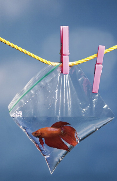
The Master flash can be used as flash and transmitter or as transmitter only if no light from the camera position is desired. Used as transmitter only, the Master will still appear to fire. This is a low-powered Wireless TTL pre-flash signal and will have no adverse effect on the photograph. The most common effect is a secondary central catchlight (reflection of the Master flash) in a subject’s eye or a reflective surface. The Wireless TTL transmitter signal works when fired through diffusion panels, softboxes, and other light modifiers, allowing all sorts of choices in light quality (see the section Modifying Flash: Quality of Light on page 132). Plastic bags can be used for lighting effects and/or weather protection (see the section Accessories on page 147).
Refer to the manufacturer’s flash instruction manual for specific information on operating the flash as a Master.
Nikon: Some cameras have a built-in Wireless TTL transmitter system, providing Wireless TTL for a single or multiple Remote Nikon flashes. Activate the transmitter by setting the camera to Commander Mode. The SB-900 and SB-800 operate as either Master or Remote. The SU-800 Commander device operates as a Master only.
Canon: The 550EX, 580EX, and 580EXMkII are interchangeable as Master and Slave. The optional STE-2 transmitter, used in place of a flash as a Master, can control up to two groups of Slave flashes.
The Nikon SB-900, SB-800, SB-600, Canon 550EX, 580EX, 580EXMkII, and 420EX have built-in Wireless TTL receivers. Any of these flash units can serve as a Remote/Slave with a compatible Master.
Refer to the manufacturer’s flash instruction manual for specific information on operating the flash as a Remote/Slave.
In every photograph the subject is always the same: light. Learning how to see light is the first step to a good photograph. Learning how to control light is the second. With one or more Speedlights, photographers can mold light into various forms — transforming a flat scene into one with depth and dimension. Bounce a Speedlite off a reflector, and you increase the light source; diffuse a Speedlight with a diffuser, and you soften the light. The creative possibilities are endless — when you take control of the light. | ||
| --Rick Sammon | ||

Canon: Activate the receiver by setting any flash to Slave. Any EX flash can be operated as a Slave.
Nikon: Activate the receiver by setting any flash to Remote.
The SB-900, SB-800, and the SB-600 can be operated as Remotes.
A to Z
pigeon, (p![]() j’
j’![]() n), n. 1. grip equipment for photography, film and video. 2. metal plate with a mounting stud used to position a light low to the ground, much lower than a stand can go. 3. small, low light stand.
n), n. 1. grip equipment for photography, film and video. 2. metal plate with a mounting stud used to position a light low to the ground, much lower than a stand can go. 3. small, low light stand.
The advent of cordless, TTL-controlled flash is an amazing development of the digital age that is often overlooked. For my money, the ability to get professional-looking results from multiple flash setups with point and shoot simplicity is one of the major appeals of digital photography. | ||
| --Bob Krist | ||
Different from the accessory triggers for most strobes, the signal for Wireless TTL is not infrared or radio activated. They are coded pre-flashes. For multiple Remote/Slave(s) to work they must “see” the light pulses from the Master. This direct path is called Line of Sight. Obstacles or barriers that block the light signal can prevent Wireless TTL from working or give unreliable results. In small, light-colored interiors, the Wireless TTL signal from the Master may sufficiently bounce off s urfaces to fire all Remote/Slave flashes even if the receivers are not facing the transmitter. But for most situations, and especially outdoors, anywhere the signal does not bounce, line of sight is required between the Master transmitter and the Remote/Slave receiver(s).

When set to Master, the flash will automatically zoom to the 24 mm lens setting to provide the widest spread of the Wireless TTL signal. In general, the Wireless TTL signal from the Master radiates in an 80 degree wide “cone” in front of the Master, and is effective to over 30 feet outdoors and over 40 feet indoors. The Manual Zoom feature is still operable on the Master, but changing the angle of illumination from the Master also changes the spread of the TTL transmitter signal.
The Speedlights’ bounce and swivel head can point the Master at a Remote/ Slave behind or beside the camera. A TTL cord connected between camera and Master enables use of the Master off the hot shoe.
In some lighting scenarios, no direct line of sight between Master and Remote Slave is possible. Examples are a background light or veil light behind a subject or in a bank-light pointed toward the camera. The electronics are sensitive enough that reflector discs, reflector panels, and mirrors can be used to bounce the Wireless TTL transmitter signal around corners and at angles to the Remote/Slave. Because of the interchangeability of Master and Remote/ Slave, you can place flashes to receive the signals in clever arrangements to ensure that they all get the message.
Release yourself of the idea that Master/Slave or Master/Remote connotes any pecking order. The Main light may be quite removed from the camera. The Master should be thought of as 1—a controller, 2—a trigger, etc.
Wireless TTL: Remote/Slave ID Groups
Remote/Slave flashes can be identified as Group A, B, or C. All Groups fire at the same time. Flash power for each Group is adjusted by changing Flash Exposure Compensation settings on the Master. More than one flash can be assigned to the same Group. Multiple flashes assigned to the same Group will provide approximately the same flash output. The camera’s computer views all flashes within the same Group as a unit.
Nikon: Master is identified and controlled separately as an M.
Canon: Master is always part of group A.
Wireless TTL exposure control for multiple Groups is illustrated by the following flow chart:
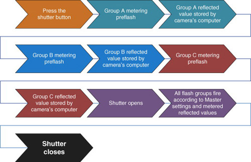
A Master Speedlight can activate three groups and, according to Nikon, there is no limit to the number of Speedlights in each group. But is there eventually some limit to the number of Speedlights that can be used in a shot? Does the pre-flash process take longer if we add lights? Since light actually travels one foot in about a nanosecond, the distance between the Speedlights is insignificant. Each of the groups makes a separate light measurement, in sequence, but this time delay does not depend on how many Speedlights are in the group. The camera’s computer makes the final exposure calculation based on the light measurements from the Master Speedlight and up to three Remote/Slave groups. Theoretically the calculation is only based on a maximum of four light measurements and does not take any longer if more than one flash is in a group. The final data transmission to each of the remote groups and the firing of the flashes is also independent of how many Speedlights are in any one group.
The answer is ultimately one of practicality. How much light do you need? Is AC power available? For a location shot, packing several Speedlights might be a little easier, assuming you own several Speedlights. Finally, there is a cost trade-off that really depends on your ambitions as a photographer.
Four proprietary Wireless TTL operating Channels are available from each manufacturer. The Master will ignite all the Remote/Slave(s) set to the same Channel (and only those set to that channel) at the same time. Multiple operating Channels avoid interference from other photographers using same-brand Wireless TTL in the same location (see the section Wireless TTL: Privacy on page 108).

Only the same manufacturer’s flashes set to Master and set to the same Channel will fire Wireless TTL Remote/Slave(s). The light of “point and shoot” flashes will not trigger Wireless TTL Remote/Slave(s) nor are they fired by the same manufacturer’s flashes not set to Master.
Both Nikon and Canon are proprietary systems with four interflash communication Channels. Four Nikon photographers can utilize Nikon Channels 1 through 4. Four Canon photographers can utilize Canon Channels 1 through 4. All can have a flash set to Master. Eight different Wireless TTL lighting setups can fire in the same room with no interference.

The following lists provide the basic settings for preparing a Wireless TTL multiple flash setup.
Nikon SB-900 or SB-800 as transmitter only with one or more Remote Groups
On-camera flash Mode to “-----”
On-camera flash to Master
Remote(s) set to A, B, or C as needed
Master and Remote(s) set to the same channel: 1, 2, 3, or 4
Nikon SB-900 or SB-800 as flash and transmitter with one or more Remote Groups
On-camera flash Mode to TTL
On-camera flash to Master
Remote(s) set to A, B, or C as needed
Master and Remote(s) set to the same channel: 1, 2, 3, or 4
Canon 550EX, 580EX, or 580EXMkII as transmitter only with one Slave Group:
On-camera flash switch to Master
On-camera flash Master Unit Flash off
Ratio off
Slave(s) set to A
Master and Slave(s) set to the same channel: 1, 2, 3, or 4
Canon 550EX, 580EX, or 580EXMkII as transmitter only with two Slave Groups:
On-camera flash switch to Master
On-camera flash Master Unit Flash off
Ratio on
Ratio A:B
Slaves set to A and B as needed
Master and Slaves set to the same channel: 1, 2, 3, or 4
Canon 550EX, 580EX, or 580EXMkII as transmitter only with three Slave Groups:
On-camera flash switch to Master
On-camera flash Master Unit Flash off
Ratio On
Ratio A:B:C
Slaves set to A, B, and C as needed
Master and Slaves set to the same channel: 1, 2, 3, or 4
Canon 550EX, 580EX, or 580EXMkII as flash and transmitter with one Slave Group:
On-camera flash switch to Master
On-camera flash Master Unit Flash on
Master is always part of group A
For Master and Slave at the same flash exposure value: Ratio off, Slave ID set to A
For Master and Slave at the different flash exposure values: Ratio on, Ratio
A:B, Slave ID set to B
Master and Slaves set to the same channel: 1, 2, 3, or 4
Canon 550EX, 580EX, or 580EXMkII as flash and transmitter with two Slave Groups:
On-camera flash switch to Master
On-camera flash Master Unit Flash on
Ratio on
Ratio A:B or A:B:C as needed
Slaves set to ID A, B, C as needed
Master and Slaves set to the same channel: 1, 2, 3, or 4
Canon 550EX, 580EX, or 580EXMkII as flash and transmitter with three Slave Group:
On-camera flash switch to Master
On-camera flash Master Unit Flash on
Master is always part of group A
Ratio On
Ratio A:B:C.
Slaves set to ID A, B, C as needed
Master and Slaves set to the same channel: 1, 2, 3, or 4
To continually emphasize this paradigm shift in digital/Speedlight technology, we no longer rely on the old habits of controlling flashes with aperture and shutter speed and manually raising and lowering flash power. Now all decisions go through two independent computers, one in the flash and one in the camera, and they insist on giving you “correctly” exposed images every time despite any misguided choices. But everything in TTL flash is relative. Any adjustment you make in an automatic mode tends to make all the lights re-level themselves to get the proper exposure. If you come to understand this interdependency the rest is easy. Exposure strategies for Wireless TTL multiple flash photography and mixing these flashes with existing light remain basically the same as for on-camera TTL flash. Flash exposure for each Remote/Slave group is controlled by Flash Exposure Compensation and/or Ratio settings on the Master.
Group, Flash Exposure Compensation, and/or Ratio settings in Wireless TTL may seem confusing, at first, to those accustomed to manual flash and incident metering, or those unaccustomed to working with controlled lighting. Adjustments in Flash Exposure Compensation and/or Ratio settings should be judged both visually on the LCD monitor and graphically on the histogram. Review the highlight point of the histogram to determine exposure and the shadow point to determine contrast (see the section Contrast on page 61). Believe your eyes. Wireless TTL operates by comprehension, intent, and observation, not by linear formula.

In review, Wireless TTL flash exposure is based upon reflected meter values. The Exposure Compensation for each Remote/Slave Group is set according to the brightness value desired in the image and the reflectance of the area illuminated. Wireless TTL flash Groups are adjusted in relation to each other, rather than a hypothetical baseline. In most cases, all other flashes are adjusted in accordance to the brightest flash. As more existing or continuous light is incorporated in the exposure, the overall effect of the Speedlight will be reduced. It is recommended to have a preconceived idea for each flash Group used: Main, Fill, Accent, etc. In general, satisfactory highlight exposure should be obtained before attempting to judge contrast.
Since multiple wireless TTL Speedlights work in unison, adjusting any one may automatically change others and the overall look of the picture. To illustrate the need for a visual and flexible approach to setting Wireless TTL, consider these examples:
If a Background light is made brighter or darker, the Main light may also need to be adjusted. The total amount of flash entering the camera is changed, therefore the TTL flash settings may need to be changed.
When a TTL flash Group illuminates a small portion of the subject or the frame, it will have a tendency to overexpose. A Rim light, Edge light, or Hair light may need to be set to a low value even if it is the brightest light in the image.
If a subject changes from a dark shirt to a light shirt, the TTL settings may need to be adjusted for the change in subject reflectance.
Once an exposure relationship is established between multiple TTL flashes, the camera computer works to maintain that relationship even if the lighting setup changes. Consider these examples:
Main: The Main light may be moved to create a different direction without adjusting the TTL flash settings.
Main and Fill: Once a satisfactory highlight point (exposure) and shadow point (contrast) are established, the Main light may be moved closer to, or farther from, the subject to change the quality of light without further adjusting the TTL flash settings.
Main and on-camera Fill: Once a satisfactory highlight point (exposure) and shadow point (contrast) are established, an on-camera Fill light may be moved closer to, or farther from, the subject to change the composition without further adjusting the TTL flash settings.
Main and Fill: Once a satisfactory highlight point (exposure) is established, the Fill light exposure compensation/ratio may be changed to adjust the contrast without affecting the highlight point.
In review, if the amount of existing light in the image file changes, by either exposure or actual brightness, the camera computer will adjust the flash values accordingly. The quantity of existing light in the image is changed by adjusting a camera setting: existing light Exposure Compensation, shutter speed, aperture, and/or ISO. To change the brightness value of any or all of the Wireless TTL flash Groups, adjust the Flash Exposure Compensation and/or the Ratio settings for those Groups. The amount of TTL flash in the image is altered with the brightness of the TTL flash(es).
The number of settings, choices, and decisions may be the most intimidating aspect of Wireless TTL photography with multiple flash Groups. But the system really is almost foolproof. If you succeed in getting the Speedlights to fire, the LCD will give you instant feedback as to whether they are doing what you want. Just be sure you keep in mind they are rarely making the mistake. They are simply doing what you tell them... perfectly. It is always helpful to have a previsualized purpose for each flash Group, as this gives a good starting point for Flash Exposure Compensation and/or Ratio settings (see the section Main Light and Fill Light: Definitions on page 48).

Nikon and Canon use distinctively different control protocols for adjusting the relationship between multiple Remote/Slave Groups. The following sections for each manufacturer’s Wireless TTL control system will apply a logical aesthetic and technical process to make multiple Wireless TTL more intuitive, fluid, and creative.
Canon:
The LCD panel on the Master flash features Flash Exposure Compensation and Ratio controls for Slave Groups A, B, and C. The Master is always part of Group A. All flash Groups fire at brightness values relative to each other as dictated by the photographer. The flash brightness values are also affected by the quantity of existing or continuous light. The controls for all of these light sources can soon become intuitive if time is taken to analyze the effect of each one. If the Master and all the Slaves are in the same flash Group, they might fire at different powers but will all provide approximately the same brightness value.
Use the key words to regulate the flash control to the effect desired in the image: Flash Exposure Compensation is used to adjust the flash highlights, i.e., the highlight exposure value, Ratio, is used to change contrast, often referred to as lighting ratio.
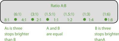
Ratio A:B establishes the brightness value relationship between Groups A and B. The Ratio is shown as units of light. The dots in between the numbers represent intermediate ratios. An A:B Ratio of 1:4 translates into one unit of light emitted from Group A for every four units emitted from Group B, resulting in Group B being two stops brighter than Group A. An A:B Ratio of 4:1 translates into four units of light from Group A for every one unit from Group B. The Ratio feature can be set to any Ratio shown on the flash LCD.
Ratio A:B:C provides the same A:B Ratio control as above, with Group C controlled by a separate Flash Exposure Compensation of “–3” to “+3” relative to the total brightness values provided by Groups A and B.
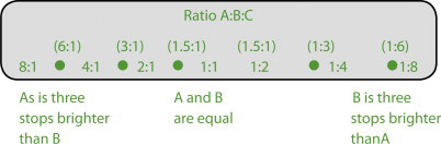
C “–3” to “+3” Flash Exposure Compensation relative to the total brightness of A:B
Flash Exposure Compensation on the Master changes the quantity of flash provided by the Master and all Group A Slaves. Since the other flash Groups respond to changes in any one flash Group, the Flash Exposure Compensation on the Master effectively raises or lowers all flash Groups equally.
Nikon
The LCD panel on the Master flash features Flash Exposure Compensation for Remote Groups M, A, B, and C. On some camera models, these controls are accessed through the camera LCD when the camera is set to Commander Mode. The Master is always Group M. All flash Groups fire at brightness values relative to each other as dictated by the photographer. The flash brightness values are also affected by the quantity of existing or continuous light. The controls for all of these light sources can soon become intuitive if time is taken to carefully analyze the effect of each one. All Remote flashes in the same Group will provide approximately the same brightness value.
The flash Group compensations are adjusted to create a brightness relationship between the Groups, rather than an intrinsic individual base.
As with traditional manual flash and Polaroids, it may take several test images and adjustments to successfully place tonal values where desired. Experimentation and experience with the Wireless TTL system will make efforts easier.
Canon Speedlites and Nikon Speedlights can be operated on Manual. The Manual mode changes the fundamental operation of the flash system, disconnecting the flash from the in-camera reflective meters and computer, returning to “old school” flash photography. In Manual flash mode, the camera’s computer will no longer change the quantity of flash automatically. The photographer regulates flash power, distance, and aperture. Each flash group will now provide a fixed, unchanging quantity of flash. Flash brightness values are changed by flash power rather than Flash Exposure Compensation.
Manual flash is a combination of the basic physics of light and photographic mechanics. Exposure for Manual flash is determined by a combination of ISO, flash power set by the photographer, flash-to-subject distance, zoom head position, and aperture. The following explains the significance of each component of a Manual flash exposure value.
ISO is the relative sensitivity to light. ISO determines the quantity of flash sufficient to properly expose capture medium.
If the range of flash power settings cannot provide the desired aperture and/or span the flash-to-subject distance, change the ISO.
Flash power changes the amount of flash. Flash power does not make the flash tube brighter or dimmer. It controls flash duration or the amount of time the flash tube is lit. Maximum flash power, also called full power, is represented on the flash LCD display as “1/1”. Maximum power is the longest duration, and the greatest amount the Speedlight can produce. Full power may be needed at small apertures, low ISO, or if the subject is far away from the flash. Minimum power produces the shortest duration. Because of the short flash duration, low flash power can freeze very fast action. Low flash power is for large apertures, physically close subjects, or high ISO settings. Flash in Manual mode is adjustable in 1/3 stop increments. The actual amount of flash is expressed as Guide Number (see Guide Number on page 10). See manufacturers’ instructions for specific steps of setting Flash Power in Manual flash mode.
The Nikon SB-900 and SB-800 are adjustable in full stop increments from 1/1 to 1/2 power, then 1/3 stop increments from 1/2 power to a minimum power at 1/128.

The flash-to-subject distance, at any power setting, affects the amount of flash reaching the subject.
Adjust the flash power, aperture, and/or the ISO to provide a correct flash exposure for a subject at any given distance from the flash.
Adjust the flash power and/or the ISO to achieve a desired aperture value.
Different combinations of flash power and aperture can all result in a correct flash exposure value.
The zoom head position controls the angle of illumination, spreading the light to cover a larger area for wide angle lenses or concentrating the light for greater range and efficient use with longer focal lengths. The zoom head position affects the Guide Number and intensity at any given distance.
Flash power and/or aperture may need to be adjusted for each change in focal length when the flash zoom is set to Auto.
Setting the zoom head manually will allow a constant aperture at different focal lengths at the same distance and same power. Set the flash zoom head manually to cover the widest focal length being used. Aperture will not have to be changed when zooming the lens to a longer focal length at the same distance.
ISO, flash power, flash-to-subject distance, zoom head position, and aperture can all be used as starting points for a Manual flash picture. When a single Speedlight set to Manual flash mode is used on the camera hot shoe, or used with a TTL cord, the LCD on the back of the Speedlight provides a guide to obtaining correct Manual exposure settings. Even in Manual flash mode the computer will continue to display information to aid the photographer.
Canon Speedlite LCD Display

The line over the distance indicates a correct flash power and aperture for a correct exposure at the indicated flash-to-subject distance.

The displayed distance indicates a correct flash power and aperture for a correct exposure at the displayed flash-to-subject distance.
The flash LCD displays usable distance when the Speedlight is connected to the hot shoe of the camera and the flash head is pointed straight ahead. It is disabled when the Speedlight flash head is tilted or swiveled, and when the Speedlight is set to Master and/or Remote/Slavefunctions. Use Guide Number, histogram/ blinkies, trial and error, or a handheld flash meter in these configurations.
Manual flash mode can provide the solution to situations where the various TTL flash modes may not seem satisfactory.
TTL flash modes can be problematic in certain fast-moving situations, such as a wedding processional where people are rapidly moving toward the camera and dressed in various light- or dark-colored clothing. In a TTL flash mode, each tonal value change in the subject requires a change in Flash Exposure Compensation to obtain a satisfactory exposure. The photographer working in a TTL flash mode may not have time or the experience to adjust to the correct compensation for each new subject hurrying down the aisle. Manual flash can provide reliable and consistent flash exposure in this situation. With Manual mode, if all people are photographed at the same distance, the same power, and the same correct f/stop, exposure values for all subjects will be correct. This is the principle of scale focusing, a simple solution for pictures of moving subjects with Manual flash.
The Wireless transmitter and receiver built into the Speedlight remain usable when the Speedlights are set to Manual flash mode. Master, Remote/Slave, Group, and Channel settings remain the same (see the sections on Wireless TTL on page 96). Wireless TTL flash modes control flash group brightness values by flash exposure compensation and/or ratio settings. It also controls flash group brightness values by changing power settings for each group. The power for each group can be selected on the Master, or each Remote/Slave flash can be set individually. Setting the Master to Manual Flash Mode will set all Remote/ Slaves to Manual. Then power for each Remote/Slave group can be set through the Master. Manual flash is not metered in-camera (some Canon camera models meter Manual flash). In Wireless Manual flash, changing the power for one group will not change the power and brightness of other groups.
Exposure and flash power settings for multiple groups of Wireless Manual Speedlights may have to be determined by measuring flash-to-subject distances and calculating with Guide Number, or by trial and error adjustment of each group’s flash power and observation using the LCD, the histogram, and blinkies. Handheld flash meters may not be effective with Wireless Manual flash, as the Speedlight’s Wireless transmitter emits a pre-flash that will give a false meter reading, often resulting in extreme overexposure. See manufacturer’s instructions regarding specific Wireless Slave/Remote operations and functions.
In summary, in a manual flash setup:
To make the light from one particular flash brighter or darker, change flash power for that flash unit only.
To make all flash equally brighter or darker without changing f/stop and ISO, equally increase or decrease the flash power on all flashes; for example, if flash power is doubled on each flash, the overall flash brightness value would increase by one stop.
When no existing light is in the picture, to make all flashes equally brighter or darker without changing depth of field, change the ISO.
If no existing light is in the picture, to make all flashes equally brighter or darker and change the depth of field, change the f/stop.
To make only existing, ambient light brighter or darker, change shutter speed.
To make both existing light and flash equally brighter or darker, change f/stop or change ISO. As the amount of existing light increases, flash power may have to be reduced to avoid overexposed highlights.
Manual flash mode allows the use of the Speedlights in conjunction with other, traditional flash units, such as studio strobes or older, non-TTL flashes.
The Nikon SB-900s and SB-800s have a built-in photoelectric eye trigger that will fire these units when it sees a light Impulse (see the section Nikon SU-4 Mode on page 97). The SB-900 and SB-800 also have traditional PC flash cord terminals, allowing triggering by wired connection to the PC[8] outlet on a camera, infrared triggering device, or radio slave receiver.
The hot shoe on the Canon Speedlites can be fitted with a variety of devices for remote triggering when the Speedlites are used with non-TTL flashes. Hot shoe photoelectric eye triggers and PC-to-hot shoe adapters allow the Canon Speedlights to be triggered by the light from another flash, or by wired connection to a PC terminal on a camera, infrared triggering device, or radio slave receiver.
The Wireless TTL signal from the Master remains effective if bounced or passed through a diffusion screen. In-camera flash metering and automatic flash exposure remain operational. Exposure strategies remain unchanged. Master and Remote/Slaves can be used with reflector panels or discs, diffusion panels, and softboxes. Several brands of 5″ × 8″ softboxes attach directly to the flash with Velcro®. Speedlights can be attached to much larger bank lights too. A variety of manufacturers produce brackets and rings to mount a TTL flash to extra small, small, medium, and large softboxes.
Various softboxes mount the flash at the rear, ideal for maintaining line of sight between Wireless TTL transmitter and receiver.
When used with Speedlights, the softbox acts as an enclosed diffuser. Figure 2.2 shows how the Speedlight fires directly toward the front panel of the softbox, which creates a larger light source and somewhat scatters the direct light. By the increase in size and the slight scattering, the softbox turns the Speedlight into a softer light source.

When used with “studio” strobe heads that have removable reflectors, the softbox becomes a mixing chamber as well as a diffuser. When the bare flash tube of the studio strobe is in the softbox, light is directed not only at the front panel, but at the internal reflecting panels of the softbox. This mixing can produce a more homogeneous, softer light from the same softbox, as shown in Figure 2.3.
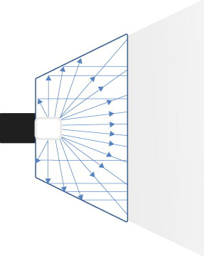
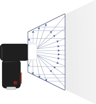
The Speedlight can be made to mimic the bare tube head. The Nikon Speedlight comes bundled with a snap-on dome diffuser. A similar diffuser is available from independent manufacturers for the Canon Speedlite. Used alone, this diffuser does not soften the light. The size of the light source remains the same. Study the edge of the shadow on the subject with and without it. The dome diffuser does bounce light in all directions. When used indoors, overall contrast is reduced and more light is provided in the background of the picture. The dome diffuser used on a Speedlight inside a softbox turns the Speedlight into the equivalent of a bare tube flash, as depicted in Figure 2.4. The quality of light from the dome diffuser Speedlight in a softbox may be softer than a “straight” Speedlight.
Softboxes are available in a variety of sizes and specifications. The larger the softbox, the softer the light. The greater the softbox-to-subject working distance, the larger the softbox needed to maintain a soft light. Silver-lined softboxes will have more contrast and specular highlight than white-lined softboxes. Several brands have interchangeable interior fabrics and secondary, removable internal diffusion baffles. Recessed front softboxes provide a more narrow angle of illumination than flush front. Recessed fronts allow more control over the spread and feathering of the light. Flat, flush fronts may be better if there is extensive use of reflectors as fill. Recessed front softboxes often can be fitted with fabric egg-crate grids, providing a soft, specific spotlight effect. Barn doors, purchased or fashioned, may be available to further control the spread, spill, and placement of the light. Circular masks change the shape of the catchlight in the eyes.
Strip boxes are long narrow softboxes designed for full length portraits and fashion, for use as edge or hair lights, or any time long, slender highlights are desired, such as in photographing bottles or glassware. Small Speedlights can be used with a large softbox. Set the zoom head to the widest to evenly illuminate the front diffusion screen.
The horizontal or vertical orientation of the softbox can change the look of the image. A vertical subject may be best with a vertical light. Group pictures may call for horizontal. Shape the light to better match the subject. Using a large softbox horizontally for a portrait may yield less contrast and more of a “wrap around” look, as the wider softbox is illuminating the subject from more angles. A very large horizontal softbox may successfully take the place of separate Main and Form Fill lights for portraiture.

Softboxes mount Speedlights on the rear of the light modifier. When the Speedlight/softbox combination is used in front of the camera, closer to the subject, it is easy to maintain line of sight between Master transmitter and Slave/Remote TTL receiver. Make sure the softbox mounting bracket flash shoe rotates to allow facing the receiver toward the transmitter while placing the flash head into the softbox.
Certain configurations, such as bounce umbrellas, may block the Wireless TTL signal and may not work well in many situations. White shoot-through diffusion umbrellas may be usable, as the umbrella does not come between Master and Remote/Slave.
Wireless TTL flashes can be modified to duplicate the same quality of light as studio flash units.
Photographers love gadgets. In an effort to capitalize on this insatiable appetite, new products are being introduced all the time. Magazines and conventions are filled with companies hawking their wares. The Internet flourishes with Web sites whose sole purpose is trade. Everyone feels they can “build a better mousetrap.”
It is unfortunate but far too many reduce taking pictures to the quality and quantity of equipment and paraphernalia. Whereas the right tool can solve a myriad of problems, a little common sense is necessary to discover just those accessories that will substantially contribute to making better images. Some are tools you need to succeed and some are merely toys. Personal style dictates what kind of equipment photographers need, that and maybe their pocketbooks.
After gathering together the basic equipment to take pictures, generations of great photographers have proven that little else is needed to make brilliant photographs. Although we could all use the proverbial compass to point toward true North, a magic carpet to raise us high above it and a “perpetual motion machine” to power it all, while we are waiting for that we all know “necessity is the mother of invention.”
The best photographers in the field display an amazing MacGyver[9] instinct whereby they enlist one tool to do the work of another and make complicated devices out of ordinary objects. That gift sometimes can prove counterproductive, because too many of us try to reinvent the wheel when we could better spend time incorporating someone else’s invention to do the job. But getting equipment to do double duty is important.
You don’t need the latest gadget. But this chapter is intended to highlight a few things that may help and a few things that show how others have already “paved the way.”
A mini stand is provided with each flash. The mini stand will hold a Remote/ Slave flash upright on any flat surface. The mini-stand has a standard 1/4″-20 screw thread on the bottom to mount on various light stand adapters and tripod heads. A “swivel adapter” or small ball head on the top of a light stand allows the flash to be aimed in different directions and angles.
A variety of light-to-medium duty light stands sufficient to hold a TTL Remote/Slave flash and a diffusion device are available at reasonable prices. Most come in 6-, 8-, and 12-foot heights.
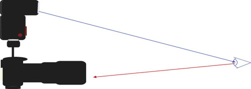
A TTL Cord allows tethered use of TTL flash removed from the camera hot shoe. The TTL Cord maintains the flash-to-camera TTL flash connections and all TTL flash features. The TTL cord allows the flash to be handheld or attached to a light stand or secured on a flash bracket. The extra distance of the flash from the camera permits more options and a more directed light. TTL cords are available from the original camera manufacturers and from several independent brand names.[10]
Canon: Canon OC-E3 off Camera Shoe Cord 3 maintains all on-camera flash functions up to two feet from the camera.
Nikon: Various TTL cords are available from Nikon. SC-17 is a simple TTL cord. SC-29 has an auxiliary Wide Area AF Assist Illuminator and is for use with a professional flash bracket.
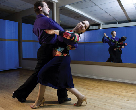
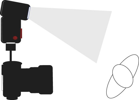
Horizontal pictures, with the flash mounted on the hot shoe, show almost no shadows. The center of the flash is above the center of the lens. When the camera is vertical with the flash on the shoe, the light comes from the side and produces asymmetric shadows. Holding the camera with the flash on the left, or on the right, can change the direction of the shadow but not eliminate it.
Red eye is flash reflecting off blood vessels in the back of the eye. Flash close to the lens axis causes red eye. Telephoto lens pictures are more prone to show red eye due to the narrow angle of reflection as a result of the increased flash-to-subject distance.
A professional flash bracket can alleviate these problems. Flash brackets that position the flash above the lens for both horizontal and vertical compositions maintain shadowless lighting. A professional flash bracket increases the distance between the flash and the lens. This creates light that is directional and reduces red eye.
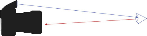
Flash brackets come in two designs: flash-rotating or camera-rotating. The flash-rotating bracket matches the orientation of the rectangular flash with the rectangular format of the camera. The camera-rotating bracket keeps the flash horizontal regardless of camera orientation. A camera-rotating bracket may result in flash pictures that are dark on the top and bottom unless the wide panel is used on the flash.
A proprietary TTL Cord is required to maintain communication between the camera and the flash when using a flash bracket.

Flash separated from the lens, such as on a flash bracket, changes the angle of reflection. Red eye is reduced or eliminated.
Figure 2.6. Red eye reduction with flash bracket.

With the flash on the hot shoe, vertical composition creates side light with strong side shadows. Holding the camera with flash on right or left changes the direction of light provided by the TTL flash.
Figure 2.8. Flash direction with vertical camera shots.
Flash-rotating brackets maintain the orientation of the TTL flash and the camera for even flash coverage. Keeping the flash centered over the lens eliminates side shadows. Increased lens-to-flash distance reduces red eye.
Figure 2.9. Flash-rotating brackets.
A to Z
paparazzi (pä’p![]() -rät’sē), n. plural. 1. term for photographers who take candid pictures of celebrities usually by relentlessly pursuing them in their daily activities. 2. word popularized after the Federico Fellini film La Dolce Vita in 1960. 3. slang term from Italian dialect word for noisy, annoying mosquito.
-rät’sē), n. plural. 1. term for photographers who take candid pictures of celebrities usually by relentlessly pursuing them in their daily activities. 2. word popularized after the Federico Fellini film La Dolce Vita in 1960. 3. slang term from Italian dialect word for noisy, annoying mosquito.
Camera-rotating brackets turn the camera vertical while the flash remains oriented for horizontal coverage. The tops and bottoms of the flash pictures may be dark. Use the Built-In Wide Panel/ Built-In Wide Flash Adapterto widen the angle of illumination from the TTL Flash.
Figure 2.10. Camera-rotating brackets.

Suffice it to say modern Speedlights have been engineered to emit every “ounce” of power. These small flashes are incredible improvements over their predecessors and exceed all expectations. They are ideal for big and little jobs. However, batteries remain the weak link. Compact strobes “eat batteries for breakfast.” For your lights to work and work well you have to keep up with their voracious appetite for energy. Even partially exhausted batteries drastically slow recycling times and may not recharge fast enough to provide a full charge.
Batteries are energy storage devices and the heart of the flash. Proper battery maintenance is essential to satisfactory flash operation. Attention to batteries is important.
Unsuitable or exhausted batteries can overheat and damage a TTL electronic flash. Old or damaged batteries can leak corrosive chemicals, ruining the flash.
Use only fresh batteries of the same brand and purchased at the same time. Do not mix.
If the recycle time exceeds 10–12 seconds immediately change to fresh ones.
Flash recycling times are dependent upon the flash power required for each picture, type of batteries used, and their condition.
Do not leave batteries in the flash for extended storage. If the flash will not be used for several weeks, remove them. Even with the flash turned off, the batteries are making a connection with metal contacts causing battery drain. Over time they can become exhausted and leak if left in a device.
Do not use carbon-zinc batteries in the electronic flash, even if they are labeled “heavy duty.” Carbon-zinc batteries do not satisfy the power requirements of the TTL flash, and will damage it.
Carry spare sets of fresh batteries.
Regularly inspect your batteries for contact condition, case damage, and leakage.
Alkaline batteries are readily available, reasonable in price, provide good performance in TTL flash units and can only be used once. Alkaline batteries may lose power quickly in temperatures below freezing.
Lithium batteries are readily available, more expensive, provide more flashes than alkalines, and can only be used once. Lithium batteries are excellent back-up batteries. They have extended shelf-life and can hold full power for up to three years of storage. Lithium batteries may provide better cold weather performance.
Nickel-Cadmium (NiCd) batteries are rechargeable, readily available, and reasonable in price. NiCds require a compatible charging device, hold charge over extended storage, and can be used for up to 200+ charging cycles. Some NiCd batteries are prone to “memory” problems, where continued partial discharge/full charging cycles can lead to a dramatic reduction in capacity. Fully discharge NiCds before charging to avoid decreased performance. NiCds will provide faster recycling but fewer flashes than alkaline batteries.
Nickel Metal Hydride (NiMH) batteries are rechargeable, readily available, and reasonable in price. NiMH batteries require a compatible charging device, and may provide up to 1,000 charging cycles. Quick-chargers may decrease battery life due to heat damage. These batteries gradually lose power with storage. “Top off” the charge immediately before use. They occasionally should be fully discharged before charging to maintain battery performance. This is called refreshing the battery. They can provide faster recycling and more flashes than alkaline, lithium, or NiCd. The higher the current rating, in milliamp hours (mAh), the greater the number of flashes. Look for NiMH batteries of 2,000 mAh or higher. They also provide good cold weather performance.
External battery packs can provide extremely fast recycling and high numbers of flashes for extended shooting sessions. These may use multiple expendable batteries or feature high-voltage rechargeable battery cells. External battery packs are available from a wide variety of manufacturers. They are a staple for professional shooters.
Canon: The Compact Battery Pack CP-E3 takes eight AA alkaline, lithium, or NiMH batteries. The 580EX and 580EXMkII can be set, through the flash Custom Function menu, to be powered by a combination of internal and external batteries or by the external power supply only.
On location you may have to use almost anything to get the shot, especially when traveling fast and light. The most mundane household items may be pressed into service. Ordinary 8 1/2″ × 11″ white typing paper makes a great reflector, diffuser, or gobo. But if you tape two sheets together along three edges you create a versatile mini diffuser. Slide the Speedlight between the two sheets on the open side and you have a handy backlight. If you put it between the subject and the background and point it straight up, it lights both with soft light and falls off around the edges quickly. (See Figure 2.12.)
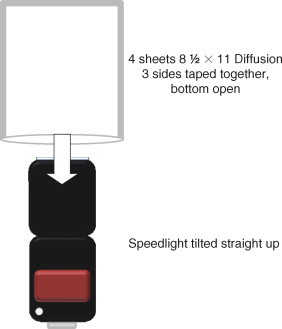
Ask the closest secretary if they have a couple of sheets and some tape. You can also make more durable versions with plastic or other diffusion materials. Works wonders.
To survive in photography you have to be resourceful. No need to run out and buy the latest and most expensive equipment. Often custom or makeshift methods are just as good or better. The mechanisms for attaching Speedlights to stands or softboxes or umbrellas are rarely very universal. Many companies make merchandise but most are single use items. Often they utilize the hot shoe attachment on the bottom of the Speedlight, which is a very weak connection. It is susceptible to cracking or breaking when any weight or leverage is applied to the structure.
With a lot of ridicule I started using large A clamps a long time ago to good effect. A Speedlight fits between the jaws perfectly and the two handles serve as outriggers that can be clamped, taped, or tied to almost anything. I use another clamp to attach the assemblage to softboxes. It is secure and solid. It may look kludgy but it works.
In lieu of the little stands that come with each Speedlight, you can always use an A clamp to stand it up on a table or shelf. The small stands hold the lights well, but as soon you add any type of accessory (i.e., softbox, snoot, etc.) they tip over. The A clamp has enough ballast to support most attachments.
There are all kinds of diffusers. Many projects demand custom-made applications. Years ago I discovered one of the most versatile, ubiquitous, and inexpensive materials — white Glad® trash bags. In a pinch I have used a couple of the “off brands” and they worked fine, but I stick with the same brand because I know their physical properties. I always carry a box of trash bags with any lighting kit. I have jerryrigged quick light boxes, taped the bags to walls and under computers, even stretched them across picture frames to substitute for the real thing. You can cut them along a seam and double the size in single ply or keep them uncut as two-ply. They are color balanced (even cut out excess UV from flash) and can be cut to any shape. I have even used Glad bags as the actual background for backlit subjects. Use them and throw them away.
A cheap trick that professionals have been using for years is to get the free sample books of gels from Lee® or Roscoe® filters. You can send away for the booklets or pick them up as “swag” at tradeshows or conventions. The gel sizes are small but they are perfectly shaped to attach to the front of a Speedlight. The variety of colors can enrich your photography immensely. The companies have caught on to this “misuse” of the “giveaway” packages, so cherish them when you find them.
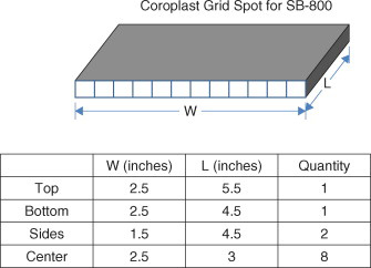
One of the cleverest DIY accessories is a grid spot for Speedlights. I found the original prototype online. The grid spot is made from a corrugated lightweight plastic called Coroplast®. Buy it in black. For the SB-800 Speedlight cut the pieces according to the table below and assemble with gaffers tape. For other Speedlights, make minor adjustments to the widths depending on the size of the Speedlight head. (See Figures 2.13 and 2.14.) You can also try various lengths to vary the effect.

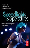
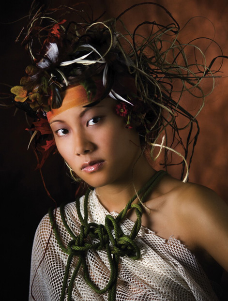
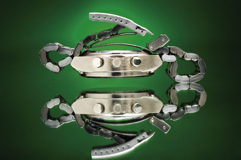
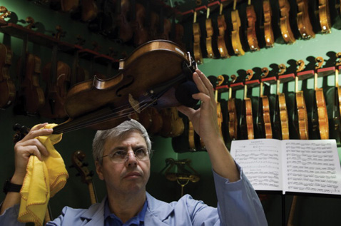
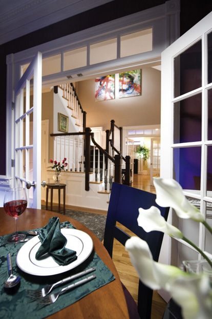
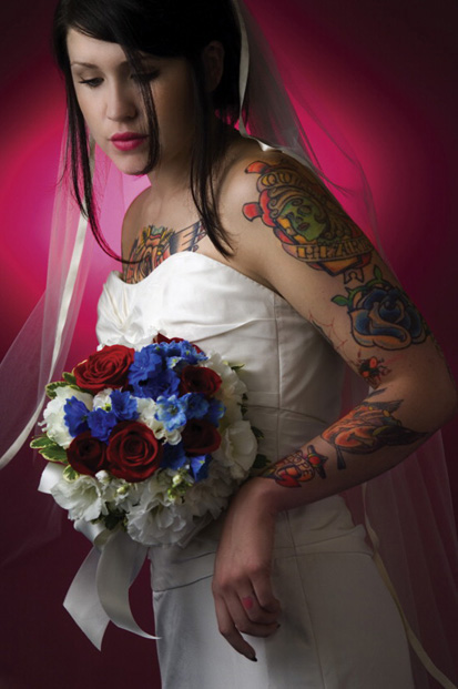
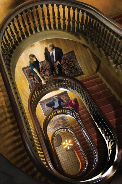
[*] Doctor For many years I have photographed health care assignments: hospitals, pharmaceutical companies, medical schools, insurance companies. Getting good photographs in these places is all about access. And once in operating rooms, research facilities, and nursing homes, speed is a big issue. The situations can change quickly because of vacillating health conditions, privacy issues, or patient’s whims. We used only three Speedlights for this photograph, all outfitted with softboxes: small, medium, and large. We added light gels to two of the flashes, green to the lightbox used to illuminate the CAT scans and chemical beakers in the background. I was trying to duplicate the fluorescent color it normally emitted and light blue on the flash and small softbox directly behind the foreground CT scan. We were directed to emphasize the doctor in an environmental portrait. Strategic placement of Speedlights can be very directional and increase the drama of a potentially mundane scene. (See lighting diagram on page 200.)
[5] One Two Three ... Infinity: Facts & Speculations of Science by George Gamow.
[6] The exception is with combinations of specific Quantum® flashes with Quantum® radio slaves that together provide a version of Wireless TTL.
[7] Normal focal length is approximately 30 mm for a 1.6× sensor, 35 mm for a 1.4× sensor, and 50 mm for a 35 mm full frame sensor camera.
[8] A PC cord is a simple wired connection between the flash and camera or the flash and a triggering device. The PC cord carries only a firing signal. It does not transmit exposure information. A PC connection terminal is found on many cameras and remote triggering devices. It is a round connection terminal with a single pin protruding in the middle. PC cords are available in a variety of styles, lengths, and from many manufacturers. The “PC” refers to Prontor® and Compur®, the two shutter manufacturers that collaborated to standardize this connector.
[9] Angus MacGyver was an American TV character known for his inventive use of common household items to improvise complex devices to extricate himself from life-or-death situations.
[10] Paramount Cords (www.paramountcords.com) custom-manufactures Nikon TTL cords in any length, and can provide Nikon TTL cord for consumer modification. Michael Bass (www.michaelbassdesigns.com).