Chapter 5
The Building Envelope
Michael Beaven1, Mick Brundle1, Paul Dickenson1, Miles Keeping2, Robert Pugh1 and David Shiers3
1Arup Associates, London, W1T 4BQ, UK
2Hillbreak Ltd., Buckinghamshire, HP18 9TH, UK
3School of the Built Environment,, Oxford Brookes University, Oxford, OX3 0BP, UK
The building envelope includes any part of the building which separates the external and internal environments, also the ground floor, outer walls, roof, windows and doors.
Enclosing and fitting-out a building provide shelter from rain, wind, snow and extremes of hot and cold, offering comfort and security for occupiers and users. Whilst many human settlements are still built using available local materials such as timber, mud brick, straw and stone, most modern buildings use industrially produced construction materials and advanced technologies to provide a high level of moisture-and-sound resistance, structural stability, thermal comfort and energy efficiency.
Some historic examples of the use of stone and timber can be seen at the websites below including Neolithic stone buildings at Skara Brae on Orkney, Scotland and a reconstruction of a Neolithic fortified village showing a palisade wall and stilt houses at the Pfahlbau Museum Unteruhldingen, Germany.
- http://jmir3.no.sapo.pt/Ebook2/History.of.Building_Britannica.Parte_1de%202.pdf
- https://en.wikipedia.org/wiki/History_of_construction)
In the United Kingdom, materials such as locally produced thatch for roofs, timber framing and ‘wattle and daub’ walls and traditional Cob walling (earth, water and straw) are still to be found in many older properties, particularly in rural areas (https://en.wikipedia.org/wiki/Wattle_and_daub; https://en.wikipedia.org/wiki/Cob_(material); https://www.youtube.com/watch?v=2E03Z8Jn2vw).
In many countries, an expansion in trade and economic growth drove demand for new residential, commercial, industrial and institutional buildings from the Middle Ages onwards. In response, technological developments, an improved understanding of the science of materials, building standards and construction technologies consequently became more sophisticated. During the 19th century in the United Kingdom, this process was accelerated by the industrial revolution, the migration of people to towns and cities and an expanding population. As a result, construction on a commensurately industrial scale took place using factory-made materials produced by increasingly advanced manufacturing techniques.
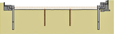
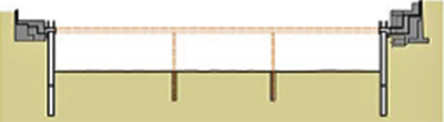
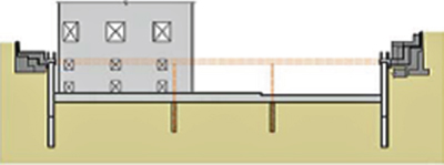
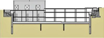
The design drawing for a typical house from 1898 on page 1 of the UWE website below, shows a timber-roof structure of rafters and purlins supporting clay tiles or slates, enclosing a normally uninsulated roof space. The outer walls were solid 225 mm thick brick, internal partitions were a single brick thick and the timber-ground floors were suspended above bare earth in the main rooms, but with a solid concrete floor in the kitchen and scullery areas. The foundations for the main walls and the ‘sleeper walls’ supporting the raised timber-ground floors are brick, standing on concrete supports or ‘footings’.
The diagrams above also explain the evolution of methods used to support the imposed loads (occupiers, furniture and equipment, snow and lateral wind loads) on buildings and of the self-weight of the construction materials used. The function of any foundation system is to safely transmit structural loads to the ground, so that the building remains stable and safe. The diagrams show how main external and internal (load bearing) walls of the house are supported by concrete foundations in the form of strip, raft and pile foundations.
As residential, commercial and institutional buildings become larger, the depth, mass and complexity of the foundation system used often increase and can represent a large proportion of the money and time expendedhttp://www.buildingregs4plans.co.uk/foundation_floor_wall_3d_detail.phphttps://www.youtube.com/watch?v=J9MzxAzP1pYhttp://www.designingbuildings.co.uk/wiki/Pad_foundationhttp://civilconstructiontips.blogspot.co.uk/2011/06/pad-foundations.htmlhttps://en.wikipedia.org/wiki/Deep_foundationhttps://www.youtube.com/watch?v=PqcPHsiBFQchttp://environment.uwe.ac.uk/geocal/foundations/Fountype.htmhttps://www.youtube.com/watch?v=vc4_5M1rhFg.
A typical 1930s house (shown below) would also have had solid brick outer walls (later with cavities for better damp resistance and thermal performance) and would also often be rendered or ‘pebble-dashed’. The internal partitions were of brick, concrete block or timber stud and the roof was made from timber rafters, roof trusses or frames supporting a clay tile or slate roof covering. The dimensions are shown in feet and inches:
However, from the 1920s onwards, cavity walls increasingly became the external wall construction of choice for architects and builders and after 1945, virtually all new houses used this form of outer wall. Most were formed of two brick ‘skins’ or ‘leaves’ (or an outer brick and inner concrete block work skin) each approximately 110 mm/100 mm wide with a 50 mm cavity between them. The two leaves were tied together by metal wall ties to ensure structural stability with the idea of filling the cavity with insulation adopted later as the Building Regulations progressively demanded higher standards of thermal efficiency.
Note that even in pre-Industrial Revolution designs for external walls, a Damp Proof Course (DPC) was commonly inserted in the lower part of the wall to prevent moisture being drawn up from the ground into the wall by capillary action, leading to dampness inside the building. Modern DPCs are normally made from a heavy-duty PVC-based material, but in the past were made from bitumen impregnated felt, slate or other available impervious materials.
To see how the construction techniques developed, look at the diagrams on The Evolution of Building Elements website at:
For more cavity wall insulation information, see:
Pitched Roofs
Until the 1950s, domestic pitched roofs in United Kingdom were mainly constructed from cut rafters which were supported by arrangements of struts, ties and purlins (to prevent mid-span ‘sag’). Traditionally, the joints between the different hand-cut timber pieces were formed by splices or Mortice and Tenon joints, held in place by wooden pegs, but by the end of the 19th century, the timbers were often cut by machine and jointed using metal nails, screws and bolts. Small section timber battens were then fixed to the top of the rafters on to which tiles or slates were nailed or ‘hung’. Prior to the 1920s, the use of roofing felt under the slates or tiles to provide an additional rain barrier would not have been a ‘given’ and the use of insulation within the roof space toowas not the requirement it is today.
Typical forms of traditional timber-roof construction can be seen at:
Modern timber roofs are most commonly of the Trussed Rafter type. These lightweight, computer designed structures are manufactured off site and then delivered by lorry where they can be erected quickly and without the need for skilled labour. They cannot, however, be easily altered to accommodate additional storage space or extra attic rooms (https://www.youtube.com/watch?v=n0CrtpuWL4w).
Flat Roofs
Although rarely, if ever, truly ‘flat’, anything less than 100 of slope or ‘pitch’ is considered flat and most have a slight gradient or ‘fall’ to ensure that rain water runs to a suitable gulley or gutter. These roofs have provided a popular, adaptable and relatively inexpensive roofing solution, particularly since the building boom of the post WW2 period. Modern flat roofs are constructed from a wide range of materials and can achieve good thermal and weather-proofing performance (http://www.arsystems.co.uk/epdm-flat-roofing/roof-types/).
In typical domestic flat roof construction, the roof deck is normally supported by timber-roof joists and a plywood decking, the weather-proof top surface can be made from PVC-based products or from metal, asphalt or bitumen impregnated sheet materials https://www.youtube.com/watch?v=WZ6Ng6YI9OAhttps://www.youtube.com/watch?v=TpqgM-jxVAUhttps://en.wikipedia.org/wiki/Flat_roof.
In larger, non-domestic buildings, the structure of flat roofs is normally steel, concrete or a composite construction using both materials, normally with flagstone, asphalt and stone chippings or proprietary products as a top surface.
In both domestic and commercial flat roof construction, stone chippings protect the water-proof asphalt or bitumen from the harmful effects of the suns’ UV, damage from maintenance workers and the additional surface area provided by the stone chippings can speed up the process of rainwater evaporation.
Steel decking can also be used as a roofing system for pitched roofs and unlike slates or tiles, can achieve very shallow slopes without compromising the weather-proofing characteristics or being prone to lifting in high windshttps://www.nexus.globalquakemodel.org/gem-building-taxonomy/overview/glossary/composite-steel-deck-and-concrete-slab--rme3http://www.corrugatedsteelsheet.com/roofing-sheets/galvanized-corrugated-roofing-sheets.htmlhttp://www.corrugatedsteelsheet.com/roofing-sheets/corrugated_sandwich_panel.htmlhttps://6dprojects.wordpress.com/2011/08/17/roofs-construction-and-roof-covering/http://www.greenspec.co.uk/building-design/concrete-flat-roof-insulation/http://insulation.com.au/tools/commercial-product-selector/http://roofhugger.com/docs/InsulatedAssemblies.pdf.
As stated, most flat roofs have, in the past, required rain water to be drained away to a gulley by means of a slight slope or ‘fall’, normally around a 1:40 gradient. This is to prevent ‘standing water’ which increases the risk of ingress and which can, over time, damage roofing materials.
- http://www.buildingregs4plans.co.uk/guidance_flat_roof_drainage.php
- http://webarchive.nationalarchives.gov.uk/20151113141044/
- http://www.planningportal.gov.uk/uploads/br/br_pdf_adh_2002.pdf
- https://www.planningportal.co.uk/info/200130/common_projects/47/roof/4
However, the recent introduction of ‘green roofs’ has meant the adoption of new design principles. Green roofs use Sedum or other plants, bedded in an appropriate soil substrate to provide a living top surface to the roof which, offering an environment for insects and flowers, also insulates the building and safely holds and collects rain water for irrigation rather than having to dispose of what has become in United Kingdom, a valuable commodity (http://www.superhomes.org.uk/resources/sedum-roof-covering/; http://www.greenroofs.com/archives/energy_editor.htm).
Although looking after such roofs is more akin to landscape gardening than to building maintenance, as long as the waterproof materials beneath the living medium are carefully selected and detailed, these roofs can make a valuable environmental and visual contribution (https://en.wikipedia.org/wiki/Flat_roof; https://www.youtube.com/watch?v=wyNviteSOzY).
Ground Floor Construction
As with roofs, ground floors normally consist of a structure, insulation, a moisture resistant barrier and top surface. Ground floors can be made using flagstones, solid in situ concrete, suspended timber, precast concrete beam and block and finished with a wide range of hard and soft floor finishes. The floor structure is designed to carry the loads from people, furniture, equipment or even vehicles which will be imposed on the floor, whilst the top surface or ‘floor finish’ must have the appropriate resilience, durability, visual, acoustic, fire resistance and cleanability characteristics for the uses which will be carried out on it. The damp proofing of ground floors which are in contact with the ground, is achieved through the use of a heavy-duty PVC Damp Proof Membrane (DPM) which, overlapped with the DPC in the lower part of the outside walls, forms an impenetrable barrier to moisture rising up into the building.
For diagrams of basic types of floor constructionhttp://fet.uwe.ac.uk/conweb/house_ages/elements/section3.htmhttps://www.youtube.com/watch?v=I4haJf6ZiHohttps://www.youtube.com/watch?v=j5NBk2BwG0c).
Videos on upper floor construction (not part of the envelope) (https://www.youtube.com/watch?v=zin8GtugLH4; https://www.youtube.com/watch?v=YEcayBTEOt0).
Framed Construction
In high-rise office buildings, the use of a Steel Frame on which external wall cladding panels of stone, concrete or lightweight steel and glass could be attached, evolved during the last part of the 19th century and first part of the 20th century, achieving widespread use in United States during the 1950s.
See notes below on the history of high-rise building and the example of the Woolworth Building, NYC, under construction in 1908 and as completed, photographed in 1913 – a steel frame supporting terracotta and concrete cladding panels, reaching a height of 240 m or 790 feet (https://en.wikipedia.org/wiki/Louis_Sullivan#Sullivan_and_the_steel_high-rise; https://en.wikipedia.org/wiki/Woolworth_Building).
In the Seagram building of 1958, identical elevations were wrapped around a rectilinear plan, serviced by overhead mechanised air conditioning ducts. However, in 1958, insulation in the walls of buildings of this type was often minimal; energy was cheap and the technology was available to deliver round-the-clock controlled heating and ventilationhttp://www.archdaily.com/59412/seagram-building-mies-van-der-rohehttps://en.wikipedia.org/wiki/Seagram_Buildinghttps://en.wikiarquitectura.com/index.php/Seagram_Building.
In the detail drawing shown on the website below, the curtain walling detail shows the concrete fire proofing around a steel column, the glazed curtain wall sections and the top of the air supply grilles in the floor:
However, the mechanised, technologically dependent approach seen in many air conditioned Modernist commercial buildings until the 1990s, changed as designers sought to use some of the design features seen in buildings of the past to achieve cooling and ventilation and reduce heat from the sun’s rays.
In this modern office building in Brazil shown on the website below, the design strategy uses passive means to cool the building.
The screened façade on the sides blocks the rising and setting sun, while a patch of green roof and overhangs help mitigate midday sun exposure. Patios and overhangs at the front of the building scoop up the sea breezes through operable windows.
Modules set within the side of the façade indent on each floor to allow office occupants to enjoy a small patio and green space complete with trees. The front and back also have outdoor space providing views of the sea and forested hillside respectively. The building is topped off with a solar electric array to help offset power consumption.
(Michler, A. Inhabitat, 2011) http://inhabitat.com/winning-office-tower-design-marries-looks-with-efficiency/
Contemporary timber-framed ‘green’ homes in United States can be seen on the website below showing how the inside of these buildings is kept dry and well ventilated and thermal comfort is maintained.
Also see Passivhaus design principles, standards and construction techniques at:https://en.wikipedia.org/wiki/Passive_househttps://www.youtube.com/watch?v=GCA7YA_X6Lchttps://www.youtube.com/watch?v=NgDRKSQp2RI.
Modern walling materials must also have good visual characteristics, be durable, easy to maintain and be fire-resistant and in doing so, comply with the aesthetic and functional performance standards set down in development control and building code regulations.
The walls of buildings use a vast range of materials to achieve exacting standards including brick, concrete block, stone, insulated timber-framed construction, steel, aluminium and glass:
Metal cladding and roofing systems: http://www.steelconstruction.info/Building_envelopes.
Rainscreen sytems: http://www.kmearchitectural.com/technical/rainscreen/.
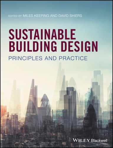
Building Envelope Design Case Example: Ropemaker Place, London 2009.
Ropemaker Place is a 21 storey office building located on the northern boundary of the City of London and the London Borough of Islington.
The original brief was for the replacement of an existing building which, coincidentally, had been engineered by Arup in the 1980s. The designs for a replacement building had already obtained Planning Permission, but following a change of site ownership in 2006, Arup Associates, the integrated architectural and engineering studio within Arup, were commissioned to re-design the existing proposals and to deliver a finished building within 3 years.
The client and building owners, British Land, also wanted a sustainable building which would reduce both operational costs and environmental impact as well as have a wide range of flexible and adaptable floor plates with high specifications to meet the needs of a variety of future tenants.
The scheme was completed in 2009. On day one, the contractual rent was £24.05 million per annum, rising to £27.5 million per annum on minimum uplifts at first reviews. On 30 September 2012, Ropemaker Place was valued at £455 million. When it was sold in 2013, British Land received net proceeds of £461 million in cash from the sale after costs, 1.4% above the September 2012 book value (British Land, 2013).
See article and videos at: http://www.architectsjournal.co.uk/ropemaker-place-london-by-arup-associates/8604601.article, http://www.arupassociates.com/cn/news/ropemaker/.
Ropemaker Place, London.
Source: Image courtesy of Arup Associates.
- The building is a 21-storey, 83,710 m2 development providing 52,000 m2 net of office space, 1297 m2 of tenant space, 1410 m2 of retail facilities at ground level and over 1850 m2 of roof garden terraces.
- The site is approximately 0.5 ha and is close to three London Underground stations and the Barbican Centre with its range of cultural and leisure amenities.
- The building cost £145 mn. Construction began in 2006 and was handed over in May 2009. Cost per sq.m. was approximately £1750.
- First office building in London to be pre-certified for the US Green Council’s LEED ‘Platinum’ Core & Shell rating.
- Energy efficiency 32.7% better than Building Regulations Part L2A: 2006 requirements.
- Building carbon emission rating (BER) of 24.6 kgCO2/m2 annually
- Air leakage rate of 5 m3/h/m2 of façade at a pressure of 50 Pa.
- Rated BREEAM (Building Research Establishment Environmental Assessment Method) ‘Excellent’ with a score of 72.7%.
- Building designed and constructed by only two organisations: Arup Associates as Architect, Structural and Building Services designer (supported with specialist consultancy from Arup and Townshend Landscape Architects) and MACE as Project Manager, Construction Manager and Cost Consultant (with in-house Quantity Surveyors, Sense).
- Designed to be suitable for multi-tenancy with a variety of floor sizes including two large designated trading floors at the first and second floor levels.
- The servicing strategy allows for market leading servicing provision with security of supply and resilience.
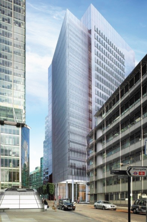
Ropemaker Place – the urban context.
Source: Image courtesy of Arup Associates.
- The developer client, British Land, wanted the building to be finished by early summer 2009, the site having been acquired by them in 2006. They felt sure that the central London commercial property market would, by the second half of 2009, be in recovery and that the building would, therefore, achieve good rental values, if let at that time. British Land also felt that building during an economic recession, whilst not without risk, was a good time to take advantage of lower construction costs
- Although the scheme which Arup inherited had obtained planning permission, early consultation with Islington Council suggested concerns about the massing of the original design and the way in which it might impact upon views along Chiswell Street on the northern edge of the site.
- Because of the client’s wish for a fast completion, both Arup Associates and the client team were mindful of the need to avoid anything controversial in terms of massing. There were potential problems of views from the South Bank of the Thames being affected by a new building, as it could interfere with the background setting of the dome and peristyle of St Paul’s Cathedral. These studies ultimately determined the maximum height of the building.
- British Land wanted Ropemaker Place to be a ‘green’ building which was flexible enough to be sub-divided to provide a good tenant mix for easier letting in what was still likely to be a tricky office market.
- Whilst time was an issue, construction cost was also a critical consideration for British Land. Their fiduciary responsibilities meant that they had to take all reasonable steps to ensure that the capital costs of the project did not jeopardise longer-term profitability for stakeholders.
- The project had to overcome the difficulties of the existing foundations. The existing building on the site had a single storey basement with foundations which included a reinforced concrete raft foundation and mass concrete fill from the earlier 1980s building. This overlaid reinforced concrete pad foundations from an even earlier 1950s building over part of the site together with 6.0 m thick perimeter existing buttress walls. The need for deeper basements to accommodate extensive services and plant thereby releasing the roof terraces for landscaped terraces, meant that excavation for new basements had to start before the main design of the building was settled. A basement design and construction strategy had to be developed whereby a supplementary Planning Permission for the basement was agreed before the main planning permission for the building, allowing work to start.
With time and money being of such critical importance to the success of Ropemaker, the development of a strong sense of trust among client (British Land), architect/engineer (Arup) and contractor (MACE) was vital. Lack of confidence in fellow key stakeholders can lead to nervousness and over-scrutiny of decision-making processes resulting in delays and additional costs.
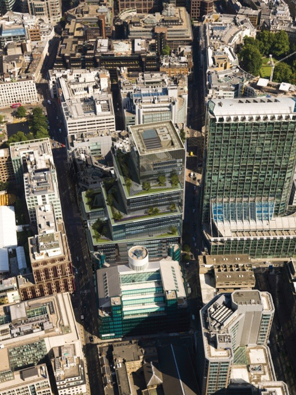
Arup Associates had successfully delivered important projects for British Land in the recent past (such as the nearby Plantation Place) and so a strong relationship already existed.
Plantation Place, City of London. Completed in 2004.
Source: Image courtesy of Arup Associates.
The contractors, MACE, were given ultimate responsibility for the delivery of all construction and building cost matters and so single points of decision-making were established in both Arup and MACE to deal with design, cost and programme issues. Communications were, therefore, simpler and as a result, a fast-track design and build programme was possible.
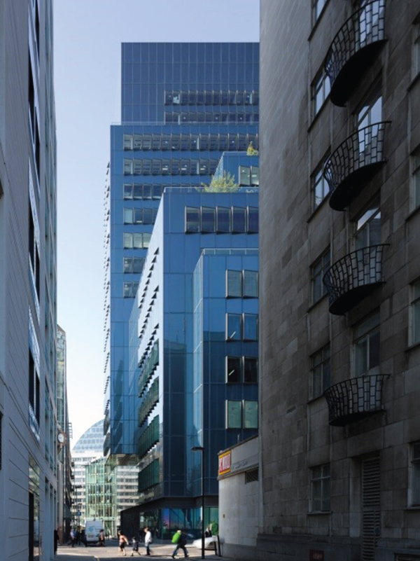
Ropemaker Place is a large building, required to sit among a variety of scales with more modestly sized buildings to the north along Chiswell Street, forming part of an existing, relatively small-scale city street.
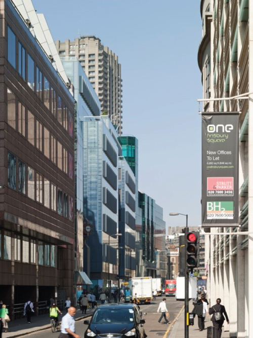
Ropemaker Place as seen looking West along Chiswell Street.
Source: Image courtesy of Arup Associates.
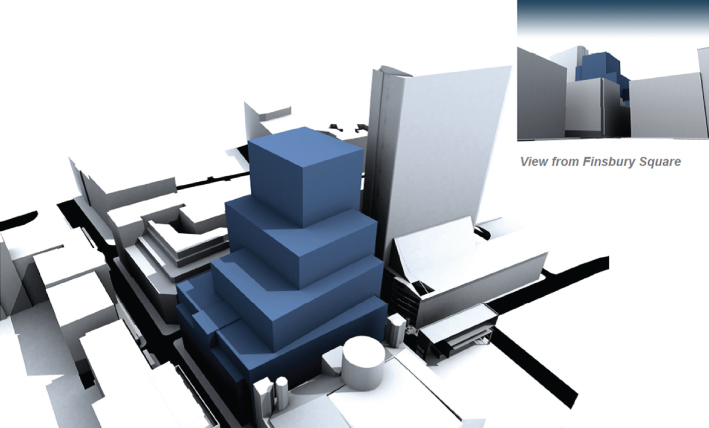
The overall architectural form was derived from several programme requirements, and from responding to the local urban realm, rights-of-light and daylighting requirements. The building was conceived as six large, interlocking cubic volumes, ascending as a series of useable garden terraces, reflecting the larger City scale towards City Point Tower and Moorgate, while respecting the smaller scale of the Islington borders. Designating the terraces as useable green roofs consigned all services plant to the basement levels and a roof plant enclosure above the top floor.
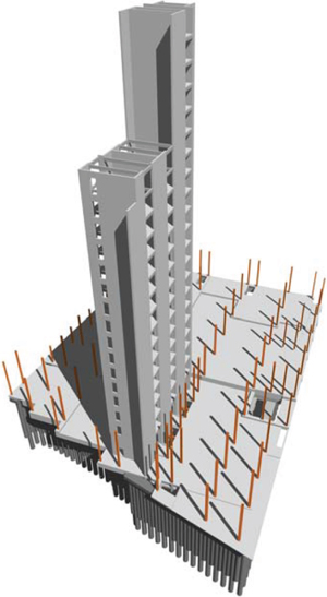
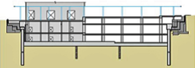
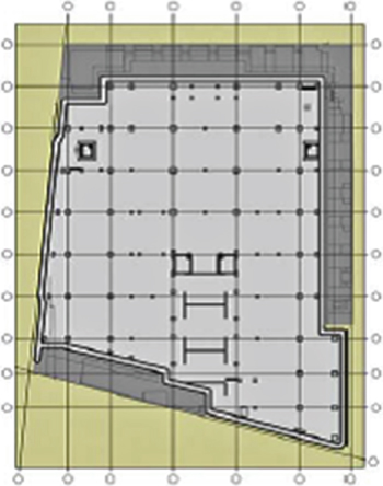
Although the site was not within any designated view corridors relative to St Paul’s Cathedral, the overall building height was determined by verified view studies, particularly from the Thames South Bank. These showed that if it exceeded 110.00 m above Ordnance Datum, the top of the building would be visible between the western towers of St Paul’s – controversial for both planning and heritage groups. This could have added significant, unacceptable risk to the programme, so the height was limited to this level (Figure 5.1).
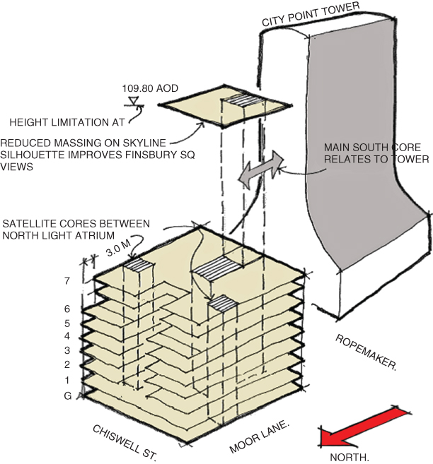
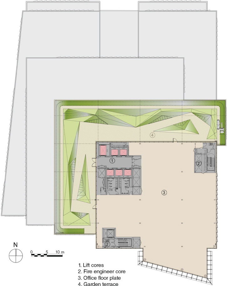
Figure 5.1 Building anatomy.
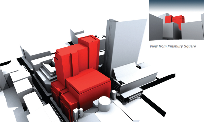
The planning authority also required that the massing along the northern site boundary of Chiswell Street be held at six storeys, with an agreed two-story setback at the upper levels of approximately 3 m from the street frontage, a condition already implemented in the recently completed block nearby at 10 Chiswell Street (not Arup designed). The planning authority’s requirement was to maintain the overall townscape massing on both sides of Chiswell Street, particularly in views along the street. Initial discussions revealed sensitivities regarding the previous consent on the site, where the mass of the tower element at the north-east corner did tend to be visible from these viewpoints (Figures 5.2–5.5).

Consented scheme views.
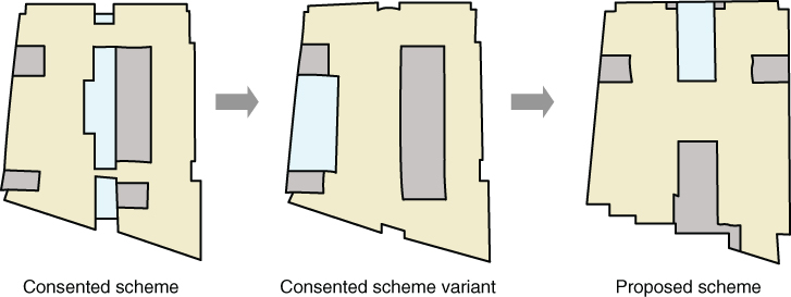
Figure 5.2 Consented scheme massing study and plans.
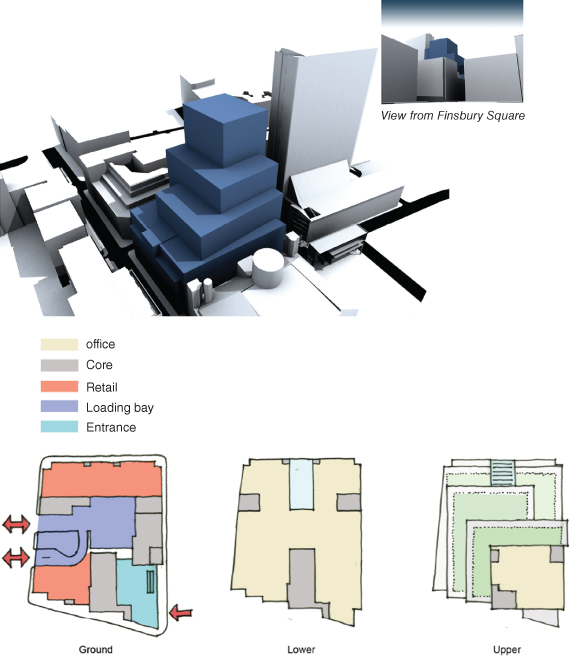
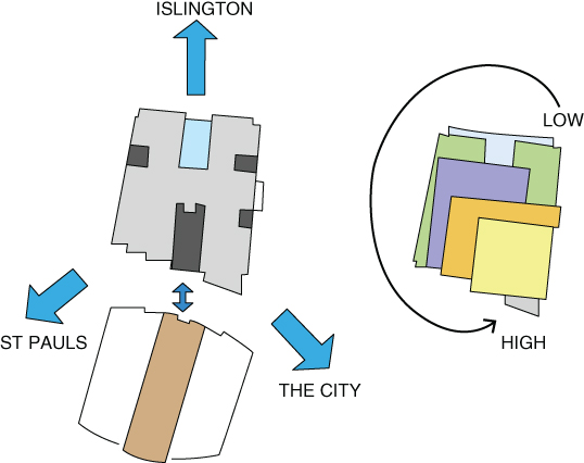
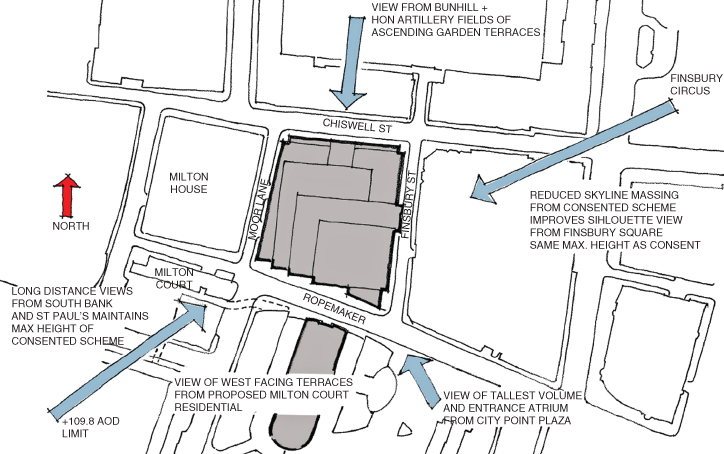
Figure 5.5 Strategic views of Ropemaker place.
Ropemaker Place was to be seen not as an object building but rather as one which would be glimpsed from the surrounding streets and a ‘good neighbour’ to its setting.
Ropemaker Place seen looking South along Finsbury Street.
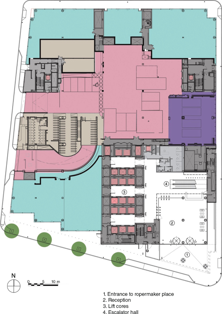
Ground Floor and Upper Level Plans
Proposed scheme massing study.
The use of the ‘green’ roof terraces within the scheme draws upon the Arup Associates tradition of creating high-quality outdoor spaces in the City and of supporting biodiversity whenever possible. The provision of such terraces on this project pre-dated the current requirements in the London Plan. These ‘green lungs’, still rare in City architecture, are an example of Arup’s interest in the greening of buildings and associated social, environmental and biological advantages (Figures 5.6 and 5.7).
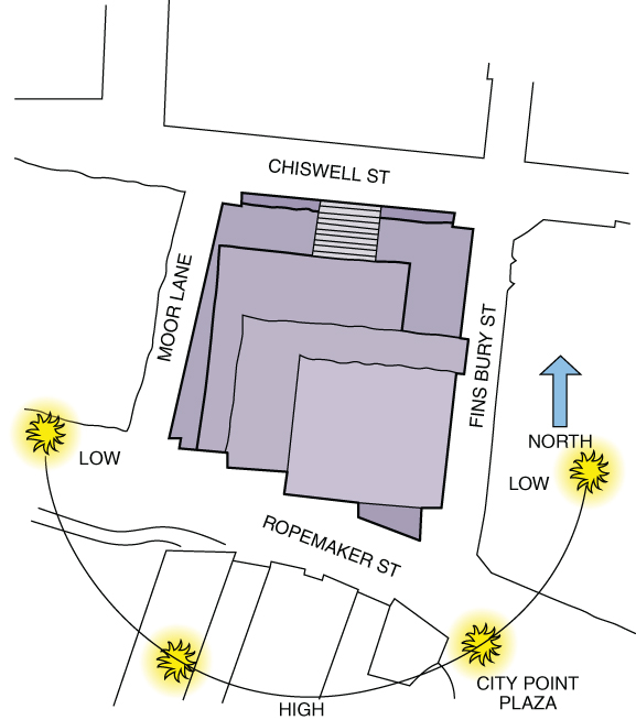
Figure 5.6 Ropemaker site orientation.
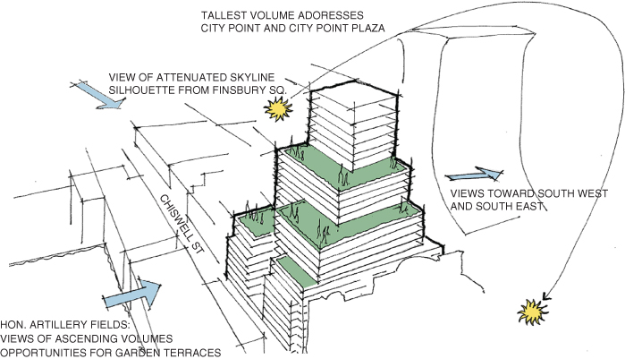
Figure 5.7 Sketch: green roof terraces and gardens.
The roof terraces at Ropemaker Place are more challenging than, for example, a sedum roof, as these need regular maintenance and good management and irrigation during dry spells. Well-designed drainage is essential, and extreme care must be taken in the detailed design and construction to avoid the risk of leaks. If substantial planting and mounding are to be incorporated, there are also structural considerations.
Green roofs serve important purposes, including absorbing rainwater, providing insulation, creating a habitat for wildlife, helping to lower urban air temperatures and combating the heat island effect. Arup Associates designed substantial roof gardens for the Wiggins Teape offices at Basingstoke (Gateway 1) in the 1970s. These were tiered terraces accessed from the office floors and mainly for occupier use, though they were also useful in supporting bird and insect life due to their diversity of planting. Similarly, the earlier Plantation Place building in the City of London was designed to incorporate on its roof terraces a series of gardens for amenity.
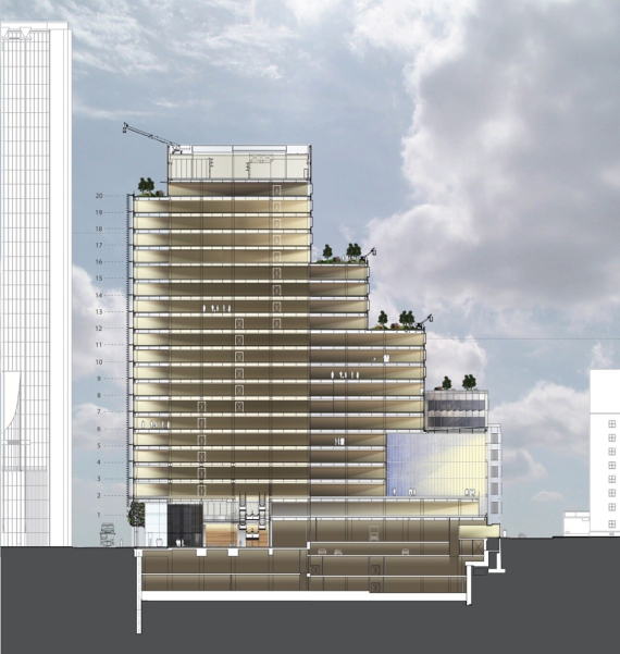
The office floors were planned on a 1.5 m grid which, coordinated with the base structural column geometry of 9.0 m × 13.5 m, gives large spans and deep, clear office plans. Floor-to-floor heights are generally 3.95 m, providing 2.75 m floor-to-ceiling accommodation with a typical raised floor zone of 150 mm.
Levels 1 and 2 were designed as dealer floors with enhanced floor-to-floor heights of 4.2 and 4.5 m, respectively; providing 3.0 m floor-to-ceiling and a 450 mm raised floor. The integrated structural services zone incorporating cellular beams is 1050 mm deep. Levels 1–16 can be sub-divided to a maximum of four separate tenancies (Figure 5.8).
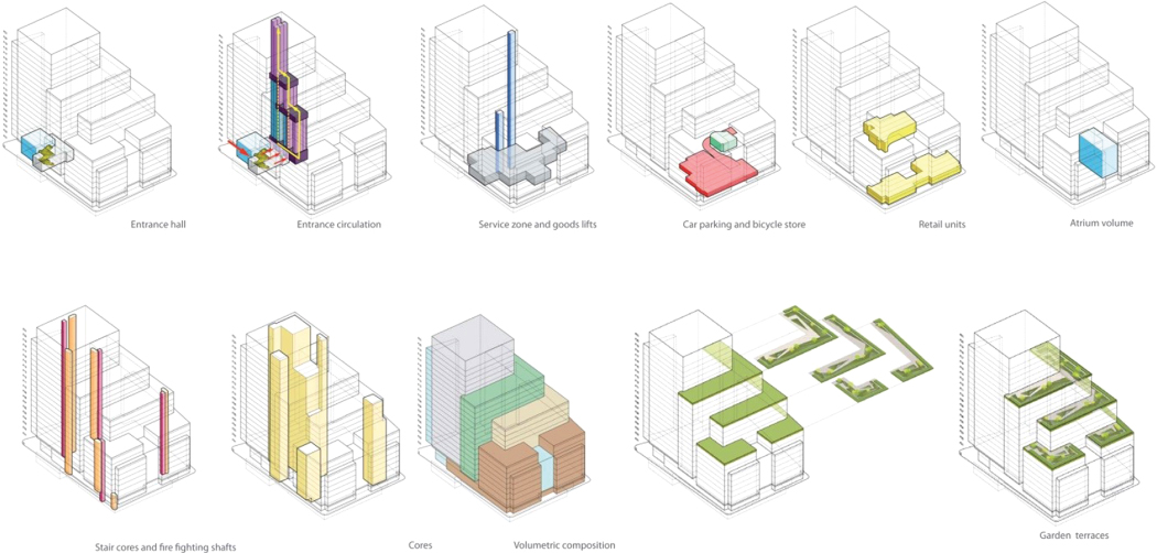
Figure 5.8 Ropemaker’s ascending landscaped garden terraces that cover most of the available roof, provide a balance between public amenity for the building’s occupants and a biodiverse habitat for insects and birds.
Arup’s lead engineer on the new project, Rob Pugh, had worked on the 1980s building and so understood the original structural design and specifications.
The team concluded that if they simply drilled through existing basement floor slab to incorporate new piled foundations; they would lose the basement area and therefore have to put services plant on the roof, meaning a waste of light-filled, valuable space on the upper storeys of the building. Also, not using roof areas for air handling plant meant that roofs could be used as external garden terraces for occupier amenity and enhanced biodiversity.
The 6-m thick existing concrete buttress retaining walls were known to have supported loads up to 12 storeys since the 1980s. As the original design information was available and core samples confirmed their structural stability, advantage was taken of the walls’ re-use as perimeter foundations of the new building as well as their retaining wall capabilities. In total 20% of the footprint of the building is supported on existing foundations, enhancing the sustainable design credentials by working with the constraints, not against them.
North-south section.
Structural Design Strategy
The structural design played a major role in enhancing the project’s success through strategic decisions to bring buildability to the heart of the design, enabling the brief, the architecture and the sustainability objectives to be delivered within the required time scale.
This involved establishing three principal phases of work, providing appropriate, efficient and economic responses to each, and ensuring an overlap between planning, design and construction.
When the client purchased the site in April 2006 with planning consent for the previous developer design, the existing building had been demolished and an extensive combination of previous 1950s and overlaid 1980s concrete foundations were left in place. This influenced the previous developer decision to limit to a single basement, leaving no option but to use the entire roof for plant. The new proposal, with its ascending garden terraces, required most plant areas to be relocated to a much deeper basement, with the remainder out of view above the ultimate storey.
The project needed to overcome the difficulties of the existing foundations, as excavation of the major new basement had to start before the new design was fully known or the new planning consent could be gained. A basement design and overall construction strategy was therefore devised whereby a supplementary permission for the basement could be found within the existing consent, allowing significant enabling works to begin. This, in turn, allowed time for the new planning approval process, and the design and award of sequential substructure and superstructure works packages to maintain the required construction time scale.
The key to unlocking this in practical terms was the way the new building and stepped massing, integrated with structural framing, was overlaid to accommodate the site constraints. The most substantial existing perimeter foundations were re-used, with excavation for the new basement only within the clearer central zone. The new building’s geometry, stepping and loading were balanced between new and existing foundations by adapting the grid to suit a predominant orthogonal central zone, with adjustable tapers at the edges. This unique harmony of architecture, formed from its urban setting as well as its physical constraints and structural response, exemplifies Arup Associates’ integrated approach to design.
The design strategy comprised the following key structural stages:
- 1. Enabling works: Demolition of existing substructure within retained perimeter buttresses, installation of secant pile retaining walls and temporary propping works, and bulk excavation as advanced works for proposed new basement substructure.
Enabling works, to give time for a new building planning application.
- 2.
Concrete substructure: Construction of a reinforced concrete raft foundation and basement framing up to ground floor to complete a substructure ‘box’.
As the superstructure stability is provided by reinforced concrete walls at the primary core, this work was also included as an independent slip-form operation in advance of the steelwork.
Concrete substructure.
- 3.
Steel superstructure: Construction of multi-storey steel framing, metal decking and normal weight concrete slabs to form the superstructure floor plates.
Steel superstructure, for fast construction of critical path façades and following trades.
Enabling works steps

(a) First stage demolition/pile probing through existing reinforced concrete raft, inside the line of existing perimeter buttress retaining walls, to form trench for new secant wall.
(b) Secant pile wall installation, with access at existing basement reinforced concrete raft.
(c) Second stage demolition/clearance to central area of existing reinforced concrete raft.
(d) Secant pile trim, capping beam, and temporary propping installation (supported on temporary piles at centre).
(e) Bulk excavation to new lower basement formation level.
Substructure and core steps
(f) Lower basement reinforced concrete raft and slip-form core commencement.

(g) Middle basement slab, beneath propping level, and removal of props from above.
(h) Completion of upper basement and ground floor slab construction, plus ongoing core construction.
(i) Steel superstructure commencement, accessed by mobile craneage directly off ground floor slab.
Superstructure supported by new lower basement raft, and by existing upper basement buttresses at the perimeter.
Enabling Works
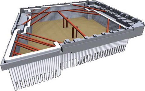
The site was an open, former single-storey basement, with existing foundations that included a reinforced concrete raft foundation and mass concrete fill from the 1980s, overlaying 1950s reinforced concrete pad foundations over part of the site, together with 6 m thick perimeter buttress retaining walls. These buttresses were known to have supported loads of a building up to 12 storeys since the 1980s.
Original design information was available and sample cores were drilled on site to prove the founding on London Clay. Since these buttresses would have presented a significant difficulty to remove, advantage was taken of their re-use as perimeter foundations for the new building, as well as their retaining wall capabilities, to limit the extent of demolition and required new retaining wall construction. In total, 20% of the footprint of the new building is supported on existing foundations, enhancing the sustainable design credentials.
Significant existing raft slab demolition and deeper excavation work were still required.
The mass of the existing foundations was exploited for use as perimeter buttress retaining walls, within which the central area foundations could be demolished and new deep excavation formed within a temporary works-supported secant pile wall.
This was deliberately positioned off grid, so that forming the basement ‘hole’ was effectively ‘off-line’ of the as-yet-unknown final building design.
This work was let as a separate enabling works package, which commenced within 6 months of the client’s site purchase.
Substructure Design
The substructure was committed to a bottom-up construction, as a site start had to be made and the piled foundation design that would have permitted top-down could not yet be defined.
A raft foundation at the central lower level was thus the most pragmatic choice to form a compatible system with the re-used existing perimeter upper level buttresses, as well as with the bottom-up construction sequence.
The design was optimised by calibrating normal software analysis and structural design techniques with more sophisticated soil/structure modelling, to more definitively assess and confirm the adequacy of overall and differential settlement characteristics. This enabled economies in raft thickness and excavation depth. The technique has since been applied to other Arup projects.
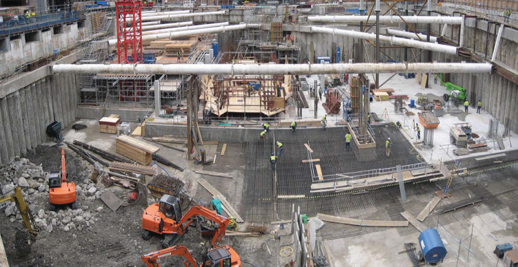
Site view to the south, showing the slip-form platform prepared for launch from the lower basement raft slab, between propped secant pile and existing buttress retaining walls.
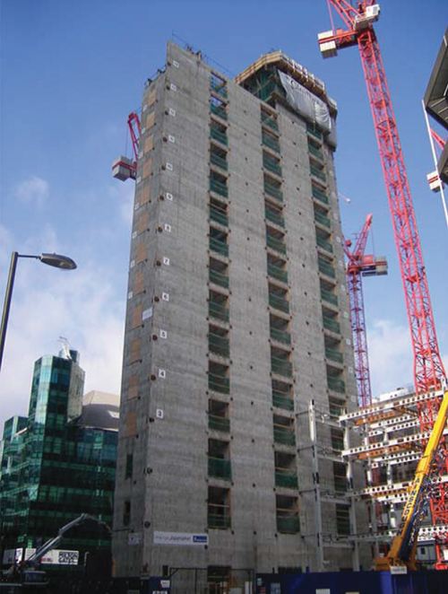
View from the south-east corner of slip-form core construction progressed to level 15 of 21, with the first four-storey bay of steelwork commenced.
The remainder of the basement substructure was in reinforced concrete, due to the short lead-in required and robust means of permanently supporting the retaining walls. As the superstructure needed to be in more lightweight steel-framed construction to satisfy the maximum foundation capacities of both the retained existing perimeter foundations and the new raft, it was practical to separate the substructure as a discrete concrete works package. This offered a longer lead-in for the following steel superstructure package. Concrete works started on the first anniversary of the client’s site purchase.
The sequence of enabling works and substructure construction was thus dovetailed to transfer basement stability from the temporary propping to permanent slab support systems
Stability Core Design
The overlap between sub and superstructure works was further enhanced by including the main slip-formed concrete stability core within the substructure package and launching it directly off the raft foundation slab.
The core essentially comprised the three connected cells of low-, mid- and high-rise lifts, stopping off at levels 8, 15 and 21, respectively. Services risers were kept outside the core walls to maintain cell simplicity and avoid complex penetrations. The risers were instead within their own ‘ring’ of column supports, which, in turn, avoided long-span floor beam reactions on the core walls, and the subsequent need for heavy connection plates cast into the core walls, further simplifying and speeding core construction.
Lobby slabs were cast in situ on permanent metal deck formwork as the core progressed, with spliced coupler joints to subsequently connect stiff ‘arms’ to bypass the services zone and maintain diaphragm integrity with the main floor plate. The concrete substructure and core to level 21 were completed 18 months after site purchase.
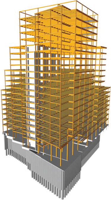
Steel Superstructure Design
Various studies were made to evaluate the preferred planning grid for the office floor plate. Essentially, all were based on steel frame with composite lightweight concrete metal decks, as opposed to concrete frame alternatives, in the interests of lightweight construction to remain within the viable capacity of the combined raft and re-used existing perimeter foundations. Long spans, 15 m and above, were generally ruled out due to the corresponding high column loads. Long spans were also not appropriate to the stepped building massing and floor plate arrangement, as they would have generated significant additional transfer structure.
The orthogonal building geometry and core anatomy were thus developed with a base, repetitive, 9 m × 13.5 m structural grid of cellular steel beams, offering deep clear floor plates, set back at grid lines to mitigate transfer structure, with a variable perimeter grid to adjust the otherwise simple orthogonal plan to suit the trapezoidal site footprint and foundation constraints.
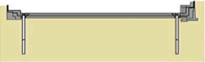
The cellular beams do not occupy the full depth of the structure/services zone, but have a reduced depth to allow fan coil condensate drains to run in a 300 mm clear zone beneath, while ductwork runs through the beams. This option also allows the tenants the alternative of fitting a chilled ceiling.
Secondary beam spacing selected was 3 m. The merits of 4.5 m spacing were studied to further reduce steel piece count and potentially enhance programme, but this was found to increase steel weight, overall building weight, performed less well dynamically, and the nominal programme advantage for steel erection did not, in principle, follow through to speed up the following cladding to improve the end date.
A study of footfall vibration effects showed the advantage of using normal weight concrete over lightweight, and so the former was adopted, to also make use of preferred site placing and finishing characteristics.
The steel frame is fully fire engineered, with fire assessment first mitigating the required fire resistance periods and thickness of any protection required, and then fire analysis defining where protection was not required. Generally, fire protection is provided to all beams that connect directly to columns, but all other secondary beams are left unprotected. Where fire protection was required, it was provided as an off-site applied intumescent coating to minimise site activity. The result saved not only the material cost of coatings, but also time and handling logistics.
Due to the eccentricity on plan of the primary concrete stability core at the south of the site, additional stability bracing was added at the secondary stair cores towards the north of the site to mitigate dynamic lateral torsional effects.
Collaboration with the construction manager and steel contractor enabled all construction logistics, temporary loadings, crane openings, and tolerance allowances to be directly incorporated into the design documentation, which was delivered in a sequence to suit the procurement and construction. Steel frame 3-D model transfer, and general fabrication drawings approval were also directly managed, with the fabricator’s modellers working alongside in the design office.
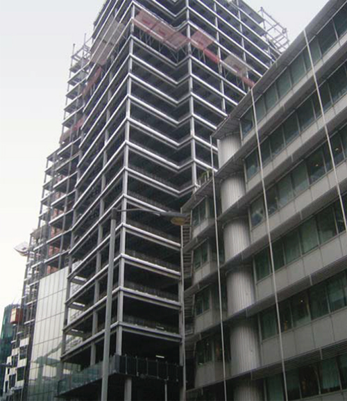
Steel frame nearing completion, and façade commenced.
Structural grid layouts.
(a) Substructure: to adjust the otherwise simple plan to suit the trapezoidal site footprint, avoid obstructions and re-use existing perimeter foundations.
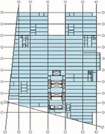
(b) Typical superstructure floors: large open floor plates, though moderated spans to balance loading between new raft and existing buttress foundations.
(c) Roof terraces: structure set back at grid lines to mitigate transfer structure.
The Façade Design
For reasons of economy, operational efficiency and sustainability, a high level of thermal performance was required on the cladding. So it was decided to develop a glazing system which would have both high levels of solar control and insulation. Primarily, this meant that the window glazing was limited to around 50% of the total façade area; this was helped by the main cores being arranged on plan so they engaged with the cladding. Furthermore, the position of the building suggested that if the windows were orientated away from the solar path, there would be advantages in reducing the cooling energy load. It was also important to the architects that the design would exploit the natural crystalline and kinetic visual properties of glass as its colours and reflective hues respond to the ever-changing qualities of natural light.
The glazing system and, in particular, the unique design of the solid glazed sections was refined in association with the artist, Antoni Malinowski, who assisted in the choice of the subtle nuances of colour. Sample glazing panels were manufactured and placed on the roof of Arup Associates studio in Fitzroy Square, London, and observed and photographed over many weeks in a range of light and weather conditions. Once the optical and colour choices of these panels were established, full-size two-storey mock-ups were built by the Trade Contractor, Schneider, adjacent to their assembly factory in Wrocław, Poland, for visual and technical assessment, as part of the procurement process.
The site orientation determined that the façades should face directly towards the north, south, east and west aspects orthogonally. The combination of the interlocking cubic massing and setbacks with the immediate architectural context creates an animated composition of light and shade from the changing sun path, varying with weather and the seasons.
A double-skinned façade, as at Plantation Place, was rejected. Budgets were limited and the necessarily deep galleries required for maintenance outside the office interior – preferred by the London market – reduced the net area substantially compared with a single-skin façade. Natural ventilation, which may have made a double-skin sensible at upper levels, was ruled out on grounds of cost and noise.
The façade design exemplifies the integration of architectural treatment with environmental performance. A bespoke system of unitised, 1.5 m wide modular cladding, designed as a series of storey-height insulated cassettes with projecting and tilting vision panels where required, provided a combination which reduced the average annual energy consumption for cooling by up to 27% compared to a flat façade.
The cladding system was installed from the individual floors using sophisticated mechanical manipulators and without expensive and time-consuming tower cranes.
Projecting Windows
Ropemaker’s façade design was key to its environmental strategy. The windows to the east and west project from the flat façade and tilt in the vertical axis away from the sun towards the north to reduce incident solar radiation, helping to reduce peak cooling loads and energy consumption. Similarly, the south-facing windows are rotated around a horizontal axis, leaning forward. The rotation allows for an element of self-shading, similar to what can be achieved by louvres and projections. A secondary effect is the reduction of solar transmission of the glazing due to the increase in the solar angle of incidence. The effect of the window geometry varies with orientation and conditions, but annual energy consumption for cooling is reduced in all cases (Figure 5.9).
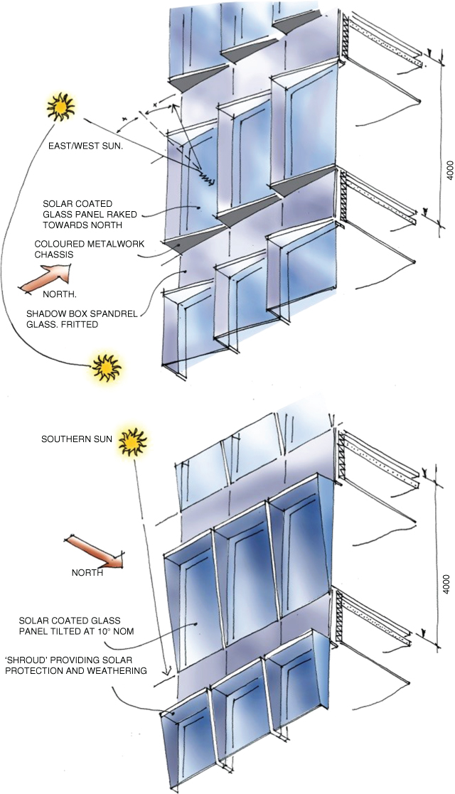
Figure 5.9 Sketch designs for tilting windows.
These projecting windows are arranged in serrated compositional blocks that, with the large areas of optical spandrel glass, create additional surface animation and modelling. The building was designed to minimise space heating demand and infiltration losses through the external fabric so that energy use for space heating was reduced; this was achieved through good insulation and airtightness in the building envelope. The use of a double pressure gasket line reduces the air leakage rate to 5 m3/h/m2 of façade at a pressure of 50 Pa, bettering the UK Building Regulations Part L requirement of 10 m3/h/m2.
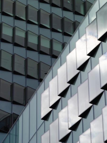
Projecting windows; tilted on the vertical axis.
Internally, the cill height of the projecting windows was fixed at 500 mm from finished floor level. This provides within the window module a usable surface that invites occupiers to use as an occasional seat and increases the area of insulated spandrel. The cill was finished with a lacquered timber panel as standard; this can be enhanced if required.
Above the main entrance loggia on the south-east corner, a projecting volume, triangular in plan, was provided with a series of external horizontal glass sunshade louvres over 20 storeys in height to attenuate solar transmission. This change to the cladding programme was for architectural and environmental reasons; the windows here are exposed fully to the southern sun with no shading from surrounding buildings, and the change of cladding grain gives the projecting volume additional emphasis on the Ropemaker Street/Finsbury Street corner above the entrance.
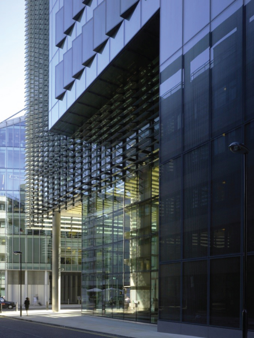
Main entrance south-east corner showing tilting windows.
Spandrel Panels
The insulated glass spandrels that cover over 50% of the building’s envelope were constructed as shadow box cassettes, incorporating a special optical glass with back panels, coloured to correspond to the cubic volumes of the massing. The layering of colour based on five different indigo tones into the interlocking cubes further enhances this changing canvas. For each block, a single colour based on the NCS Natural Colour System® 3 became the base colour to the opaque spandrel panel viewed through the glass prism.
The spandrels were designed to express depth, light penetration and reflectivity in areas of the façade where visual ‘depth’ when viewed from the exterior was desirable, but vision through the glass from the interior was not required. The ‘shadow box’ usually comprises a double-glazed clear glass unit with a coloured opaque insulated panel some distance behind the glass surface, with pressure equalisation to the exterior through a series of slot vents in the carrier frame.
The glass units are frameless and bonded back to the supporting carrier frames by structural silicone, masked by a coloured ‘frit’ band 40 mm wide and selected to align as closely as possible to the background tone when viewed through the layers of glass. This ‘kit of parts’ was completed by identically designed opening panels for smoke venting (invisibly incorporated into the system), co-ordinated air grilles, high-level plant enclosure screens and glass balustrades (Figure 5.10).
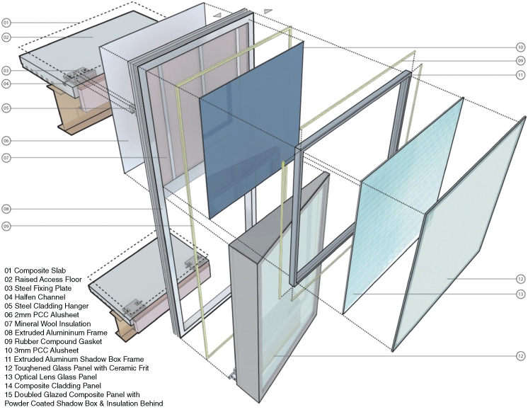
Figure 5.10 Window assembly drawing.
The overall visual effect is created by the combined properties of the lens and cladding glass unit and their relationship to the base colour. The optics of the glass dilute the colour in the encapsulated panel, producing a softer effect analogous to the addition of varnishes to base colour in Old Master paintings. Overlaid on this are sky and context reflections from the immediate surroundings.
On overcast days or in shadow, cloud reflections, the context, and lower light levels create a more muted effect. Direct sun illuminates the spandrel interior and excites the background colour. This to some extent, is obscured by light reflections from the lens glass. Viewing angles acute to the spandrel surface, such as when seeing the building along a street or at high level from the ground, tend to increase reflections and much reduce the percentage of the diffused base tone. Conversely, viewing angles more perpendicular to the spandrel surface decrease reflections and increase the percentage of the diffused base tone. The optical properties and refined detail of the glass facades, together with the interlocking cubic massing, produce an ever-changing appearance, depending on the weather patterns and ambient light of the City sky.
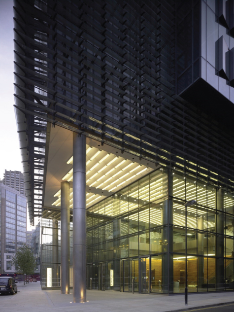
Main entrance.
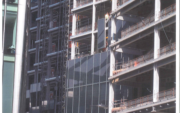
The façade panels being hoisted into place.
Energy conservation and the adoption of viable renewable energy technologies feature heavily in the building, although the team was keen to avoid ‘Greenwash’. The strategy throughout was to keep solutions simple by making the building as passive as possible.
The Construction Managers, MACE, used WRAP’s NetWaste tool, which showed the new building included 24% recycled content and 86% of materials from the site clearance were reused. 30% of new steelwork was manufactured from scrap and the existing buttress foundations on the site perimeter from the previous building were reused, adding up to 20% of the site footprint.
During construction, a Site Waste Management Plan was also in place. Construction waste was segregated into 12 different waste streams, managed and monitored, resulting in more than 75% of construction waste being diverted from landfill. Regular audits were carried out to ensure that every effort was being made to maximise the recycling of waste generated on site. To enable waste recycling during operation, dedicated recycling storage space was provided inside the building.
Wherever possible, Green Guide ‘A’ rating and responsibly sourced materials were supplied during construction. Concrete floors and roof achieved A+ Green Guide rating and frame, foundation, floors, roofs and timber finishes were responsibly sourced. Design measures to reduce waste included the Technik flooring solution that reduced waste by over 50% compared to traditional screed and prefabricated toilet construction reduced waste on site significantly. All timber used on site was sourced from sustainably managed sources.
During construction, water and energy used on site as well as energy associated to transport on site were monitored and there was Construction Environment Plan to ensure that best practice guidance was followed in respect of reducing the risk of pollution to air from dust generation. Advice was disseminated to site operatives via ‘toolbox talks’, advising on eight air pollution control measures including dust sheets, damping down and covering skips.
A petrol interceptor was included in the arrangements for the basement car park to provide onsite treatment for areas at risk from water course pollution. The strategy for water management included provision for storage and dealing with storm water run-off whilst conserving water through the design of plumbing systems.
A 90 m3 rainwater harvesting tank allows attenuation of 80% of the run-off from hard roof areas and 30% of the run-off from green roof areas; the green roof attenuating up to 70% of the rainwater that falls on it. WCs have a 4.5 l flush, urinals have IR proximity controls, and auto-shut off taps are installed. Harvested rain water has been used to flush water closets in addition to waste cooling tower blow-down water. Water to showers is limited to between 9 and 12 l/min and faucets are low flow or aerated.
Ropemaker’s Building Emission Rate (BER) is 24.6 kgCO2/m2 annually, approximately half that of a standard air-conditioned, 2008 Part L-compliant office, and is 32.7% better than Part L2A 2006. A combination of biomass boilers, foundation-stored heat harnessed by a heat pump, 75 m2 of solar hot water heating panels and 75 m2 of solar photovoltaics have been used, which provided onsite renewables (required by the Local Authority Planners) at 12–15% of the building energy demand. All exterior lighting was designed in accordance with the guidance in the Institution of Lighting Engineers (ILE) Guidance note.
The energy reduction strategy focused on an airtight, thermally efficient envelope, heat demand being minimised by recovering heat where it was not required and using it in other areas. Free cooling was maximised and the building has achieved an air leakage rate of 5 m3 of air per hour per m2 of façade at a pressure of 50 Pa.
The site location provides excellent transportation links and convenience to occupiers, as the site is triangulated by three London Underground Stations and is near the Barbican Centre with its extensive cultural opportunities. Liverpool Street Station and Broadgate are to the east of the site, with the City and its institutions beyond.
The development provides a very limited number of car parking spaces (only 23) and 54 motorcycle parking spaces. Ropemaker exceeds BREEAM requirements by providing 270 secure and well-lit cycle storage spaces, plus 15 showers with changing rooms and 235 lockers.
Ropemaker’s usable green roof terraces enhance the ecological value of the site by providing 1850 m2 of new green roof area and over 30 species of plant life including trees, shrubs and seasonal herbaceous planting, both suitable for biodiversity and occupier amenity.
Ropemaker is BREEAM ‘Excellent’ rated (score 72.7%). It satisfies the entire heating and hot water demand through the use of passive design and renewable energy systems and an array of other sustainable technical features. The building also became the first office building in London to achieve LEED Platinum, core and shell pre-certification. The building has an Energy Performance Certificate (EPC) ‘B’ rating (score of 46).
The base building heating/cooling systems are designed to allow independent occupant thermal control in all separate rooms/areas within the building. The metering strategy allows for the monitoring of different energy demands throughout the building and sub-metering is provided for each office floor.
Water meters have a pulsed output with a BMS connection to facilitate the remote monitoring of water consumption. The building incorporates a system capable of detecting major water leaks both within the building and between the building and the site boundary.
Product Design: The Wave-Form Ceiling at Ropemaker
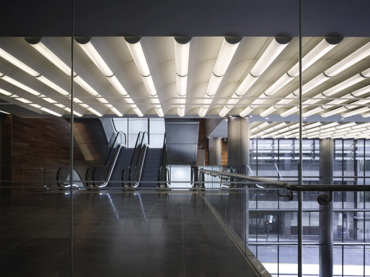
The design of bespoke façades components, furniture, and fittings in Arup Associates’ buildings has always been a natural aspect of the practice’s multidisciplinary approach. Many items are specified in the normal course of a project, but situations can arise where a particular idea cannot be resolved with available materials and components, so there is an imperative to invent from first principles. An obvious example of this is the façade cladding system at Ropemaker, whilst another is the waveform ceiling and lighting system developed for the main entrance and atrium ceilings in collaboration with Zumtobel Lighting, SAS international and Stortford Interiors. It is a refinement of similar ceilings designed with Zumtobel in previous British Land projects in the City.
The purpose was to create an indirect/direct lighting source, with an acoustic performance, giving the 10.5 m tall corner entrance foyer spatial impact and visual focus in the views from City Point Plaza and Ropemaker Street. A series of illuminated vaulted waves seem to flow into the interior, its volume perceptually expanded by the up-lit waveform surfaces.
This curvaceous profile provides a visual tour de force as well as a practical solution to the lighting and acoustic requirements. The ceiling comprises curved, preformed, white polyester powder coat, micro-perforated steel sheeting with a white tissue interlayer and an acoustic blanket, together with a clear acrylic ‘basket’ diffuser to contain the individually addressable linear fluorescent luminaires. The basket diffuser is a bespoke linear extrusion designed using Zumtobel’s patented waveguide technology, which refracts a proportion of the light flux onto the ceiling and the remainder into the interior volume (Figure 5.11).
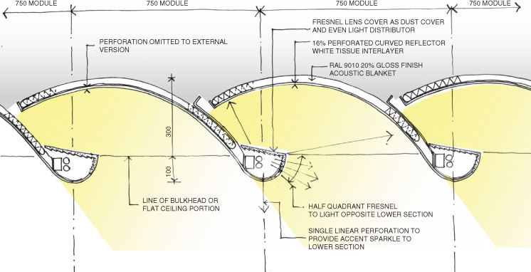
Figure 5.11 Wave-form ceiling design drawing.
The relationship between the diffused refracting light source and the reflective surfaces, together with the profile, was determined through extensive mock-ups that iteratively refined the design. Other crucial features – concealed fixing details, panel accessibility, and material finish – were also determined at this stage.
The ceiling system had to form both the main internal ceiling surface and also the external canopy surface, so as to give visual continuity between the interior and exterior systems. In practice, as both ceilings need to be fully accessible, the internal system uses a hook-on system for support, and the external system a more robust and secure suspension method.
This involves a concealed but accessible cam lock and fixed hinge to support the panels and allow access to services in the void area above.
The individual ceiling cassettes were based on a 1500 mm module (1475 mm actual), designed both to exactly fit a standard linear fluorescent luminaire and for ease of construction and replacement.
The entrance foyer, through its spacious volume, finishes, and lighting design, appears now as the main focus to the local urban context and provides a transformed backdrop to the street promenade and activities centred on City Point Plaza.
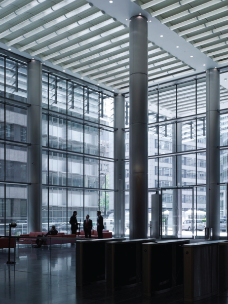
The main entrance Foyer.
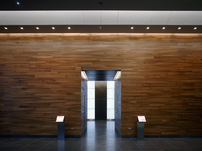
Entrance Foyer wall.
Completion
Completion of the entire building was achieved three years after the initial site purchase and within the original budget. This achievement justifies the client’s preference for an integrated design and construction team approach and reflects well on the collaborative and ‘can-do’ spirit of all those involved.
Ropemaker Place was the only UK office building to have been shortlisted for an Award in the ‘offices’ category at the World Architecture Festival, held in Barcelona in 2010.
Bibliography
- NB Sections of the text above first appeared in the Arup Journal (2010/2)
- Anderson, D. et al. (2006) The Technik floor system. The Arup Journal , (2), 34–35.
- British Land (2013) Press Release, March 2013. Accessed on 21.11.13
- Brundle, M. et al. (2005) Plantation place development, City of London. The Arup Journal , (2), 34–43.
- Building Regulations (2006) Part L: Conservation of fuel and power , Building Regulations.
- Dowson, P. (1977) Offices. The Arup Journal , (4), 2–23.
- http://www.london.gov.uk/thelondonplan/ (accessed 14 June 2017).
- http://www.ncscolour.co.uk/ (accessed 14 June 2017).
- http://www.thegreenguide.co.uk/ (accessed 14 June 2017).