2
Computer Data Representation and Operations

A major stumbling block many beginners encounter when attempting to learn assembly language is the common use of the binary and hexadecimal numbering systems. Although hexadecimal numbers are a little strange, their advantages outweigh their disadvantages by a large margin. Understanding the binary and hexadecimal numbering systems is important because their use simplifies the discussion of other topics, including bit operations, signed numeric representation, character codes, and packed data.
This chapter discusses several important concepts, including the following:
- The binary and hexadecimal numbering systems
- Binary data organization (bits, nibbles, bytes, words, and double words)
- Signed and unsigned numbering systems
- Arithmetic, logical, shift, and rotate operations on binary values
- Bit fields and packed data
- Floating-point and binary-code decimal formats
- Character data
This is basic material, and the remainder of this text depends on your understanding of these concepts. If you are already familiar with these terms from other courses or study, you should at least skim this material before proceeding to the next chapter. If you are unfamiliar with this material, or only vaguely familiar with it, you should study it carefully before proceeding. All of the material in this chapter is important! Do not skip over any material.
2.1 Numbering Systems
Most modern computer systems do not represent numeric values using the decimal (base-10) system. Instead, they typically use a binary, or two’s complement, numbering system.
2.1.1 A Review of the Decimal System
You’ve been using the decimal numbering system for so long that you probably take it for granted. When you see a number like 123, you don’t think about the value 123; rather, you generate a mental image of how many items this value represents. In reality, however, the number 123 represents the following:
- (1 × 10²) + (2 × 101) + (3 × 100)
- or
- 100 + 20 + 3
In a decimal positional numbering system, each digit appearing to the left of the decimal point represents a value between 0 and 9 times an increasing power of 10. Digits appearing to the right of the decimal point represent a value between 0 and 9 times an increasing negative power of 10. For example, the value 123.456 means this:
- (1 × 10²) + (2 × 101) + (3 × 100) + (4 × 10⁻¹) + (5 × 10⁻²) + (6 × 10⁻³)
- or
- 100 + 20 + 3 + 0.4 + 0.05 + 0.006
2.1.2 The Binary Numbering System
Most modern computer systems operate using binary logic. The computer represents values using two voltage levels (usually 0 V and +2.4 to 5 V). These two levels can represent exactly two unique values. These could be any two different values, but they typically represent the values 0 and 1, the two digits in the binary numbering system.
The binary numbering system works just like the decimal numbering system, except binary allows only the digits 0 and 1 (rather than 0 to 9) and uses powers of 2 rather than powers of 10. Therefore, converting a binary number to decimal is easy. For each 1 in a binary string, add 2n, where n is the zero-based position of the binary digit. For example, the binary value 110010102 represents the following:
- (1 × 27) + (1 × 26) + (0 × 25) + (0 × 24) + (1 × 23) + (0 × 22) + (1 × 21) + (0 × 20)
- =
- 12810 + 6410 + 810 + 210
- =
- 20210
Converting decimal to binary is slightly more difficult. You must find those powers of 2 that, when added together, produce the decimal result.
A simple way to convert decimal to binary is the even/odd—divide-by-two algorithm. This algorithm uses the following steps:
- If the number is even, emit a 0. If the number is odd, emit a 1.
- Divide the number by 2 and throw away any fractional component or remainder.
- If the quotient is 0, the algorithm is complete.
- If the quotient is not 0 and is odd, insert a 1 before the current string; if the number is even, prefix your binary string with 0.
- Go back to step 2 and repeat.
Binary numbers, although they have little importance in high-level languages, appear everywhere in assembly language programs. So you should be comfortable with them.
2.1.3 Binary Conventions
In the purest sense, every binary number contains an infinite number of digits (or bits, which is short for binary digits). For example, we can represent the number 5 by any of the following:
- 101 00000101 0000000000101 . . . 000000000000101
Any number of leading-zero digits may precede the binary number without changing its value. Because the x86-64 typically works with groups of 8 bits, we’ll zero-extend all binary numbers to a multiple of 4 or 8 bits. Following this convention, we’d represent the number 5 as 01012 or 000001012.
To make larger numbers easier to read, we will separate each group of 4 binary bits with an underscore. For example, we will write the binary value 1010111110110010 as 1010_1111_1011_0010.
We’ll number each bit as follows:
- The rightmost bit in a binary number is bit position 0.
- Each bit to the left is given the next successive bit number.
An 8-bit binary value uses bits 0 to 7:
- X7 X6 X5 X4 X3 X2 X1 X0
A 16-bit binary value uses bit positions 0 to 15:
- X15 X14 X13 X12 X11 X10 X9 X8 X7 X6 X5 X4 X3 X2 X1 X0
A 32-bit binary value uses bit positions 0 to 31, and so on.
Bit 0 is the low-order (LO) bit; some refer to this as the least significant bit. The leftmost bit is called the high-order (HO) bit, or the most significant bit. We’ll refer to the intermediate bits by their respective bit numbers.
In MASM, you can specify binary values as a string of 0 or 1 digits ending with the character b. Remember, MASM doesn’t allow underscores in binary numbers.
2.2 The Hexadecimal Numbering System
Unfortunately, binary numbers are verbose. To represent the value 20210 requires eight binary digits, but only three decimal digits. When dealing with large values, binary numbers quickly become unwieldy. Unfortunately, the computer “thinks” in binary, so most of the time using the binary numbering system is convenient. Although we can convert between decimal and binary, the conversion is not a trivial task.
The hexadecimal (base-16) numbering system solves many of the problems inherent in the binary system: hexadecimal numbers are compact, and it’s simple to convert them to binary, and vice versa. For this reason, most engineers use the hexadecimal numbering system.
Because the radix (base) of a hexadecimal number is 16, each hexadecimal digit to the left of the hexadecimal point represents a certain value multiplied by a successive power of 16. For example, the number 123416 is equal to this:
- (1 × 163) + (2 × 162) + (3 × 161) + (4 × 160)
- or
- 4096 + 512 + 48 + 4 = 466010
Each hexadecimal digit can represent one of 16 values between 0 and 1510. Because there are only 10 decimal digits, we need 6 additional digits to represent the values in the range 1010 to 1510. Rather than create new symbols for these digits, we use the letters A to F. The following are all examples of valid hexadecimal numbers:
- 123416 DEAD16 BEEF16 0AFB16 F00116 D8B416
Because we’ll often need to enter hexadecimal numbers into the computer system, and on most computer systems you cannot enter a subscript to denote the radix of the associated value, we need a different mechanism for representing hexadecimal numbers. We’ll adopt the following MASM conventions:
- All hexadecimal values begin with a numeric character and have an h suffix; for example, 123A4h and 0DEADh.
- All binary values end with a b character; for example, 10010b.
- Decimal numbers do not have a suffix character.
- If the radix is clear from the context, this book may drop the trailing h or b character.
Here are some examples of valid hexadecimal numbers using MASM notation:
- 1234h 0DEADh 0BEEFh 0AFBh 0F001h 0D8B4h
As you can see, hexadecimal numbers are compact and easy to read. In addition, you can easily convert between hexadecimal and binary. Table 2-1 provides all the information you’ll ever need to convert any hexadecimal number into a binary number, or vice versa.
Table 2-1: Binary/Hexadecimal Conversion
| Binary | Hexadecimal |
| 0000 | 0 |
| 0001 | 1 |
| 0010 | 2 |
| 0011 | 3 |
| 0100 | 4 |
| 0101 | 5 |
| 0110 | 6 |
| 0111 | 7 |
| 1000 | 8 |
| 1001 | 9 |
| 1010 | A |
| 1011 | B |
| 1100 | C |
| 1101 | D |
| 1110 | E |
| 1111 | F |
To convert a hexadecimal number into a binary number, substitute the corresponding 4 bits for each hexadecimal digit in the number. For example, to convert 0ABCDh into a binary value, convert each hexadecimal digit according to Table 2-1, as shown here:
| A | B | C | D | Hexadecimal |
| 1010 | 1011 | 1100 | 1101 | Binary |
To convert a binary number into hexadecimal format is almost as easy:
- Pad the binary number with 0s to make sure that the number contains a multiple of 4 bits. For example, given the binary number 1011001010, add 2 bits to the left of the number so that it contains 12 bits: 001011001010.
- Separate the binary value into groups of 4 bits; for example, 0010_1100_1010.
- Look up these binary values in Table 2-1 and substitute the appropriate hexadecimal digits: 2CAh.
Contrast this with the difficulty of conversion between decimal and binary, or decimal and hexadecimal!
Because converting between hexadecimal and binary is an operation you will need to perform over and over again, you should take a few minutes to memorize the conversion table. Even if you have a calculator that will do the conversion for you, you’ll find manual conversion to be a lot faster and more convenient.
2.3 A Note About Numbers vs. Representation
Many people confuse numbers and their representation. A common question beginning assembly language students ask is, “I have a binary number in the EAX register. How do I convert that to a hexadecimal number in the EAX register?” The answer is, “You don’t.”
Although a strong argument could be made that numbers in memory or in registers are represented in binary, it is best to view values in memory or in a register as abstract numeric quantities. Strings of symbols like 128, 80h, or 10000000b are not different numbers; they are simply different representations for the same abstract quantity that we refer to as one hundred twenty-eight. Inside the computer, a number is a number regardless of representation; the only time representation matters is when you input or output the value in a human-readable form.
Human-readable forms of numeric quantities are always strings of characters. To print the value 128 in human-readable form, you must convert the numeric value 128 to the three-character sequence 1 followed by 2 followed by 8. This would provide the decimal representation of the numeric quantity. If you prefer, you could convert the numeric value 128 to the three-character sequence 80h. It’s the same number, but we’ve converted it to a different sequence of characters because (presumably) we wanted to view the number using hexadecimal representation rather than decimal. Likewise, if we want to see the number in binary, we must convert this numeric value to a string containing a 1 followed by seven 0 characters.
Pure assembly language has no generic print or write functions you can call to display numeric quantities as strings on your console. You could write your own procedures to handle this process (and this book considers some of those procedures later). For the time being, the MASM code in this book relies on the C Standard Library printf() function to display numeric values. Consider the program in Listing 2-1, which converts various values to their hexadecimal equivalents.
; Listing 2-1

; Displays some numeric values on the console.

        option  casemap:none

nl      =       10  ; ASCII code for newline

         .data
i        qword  1
j        qword  123
k        qword  456789

titleStr byte   'Listing 2-1', 0

fmtStrI  byte   "i=%d, converted to hex=%x", nl, 0
fmtStrJ  byte   "j=%d, converted to hex=%x", nl, 0
fmtStrK  byte   "k=%d, converted to hex=%x", nl, 0

        .code
        externdef   printf:proc

; Return program title to C++ program:

         public getTitle
getTitle proc

; Load address of "titleStr" into the RAX register (RAX holds
; the function return result) and return back to the caller:

         lea rax, titleStr
         ret
getTitle endp

; Here is the "asmMain" function.

        public  asmMain
asmMain proc

; "Magic" instruction offered without explanation at this point:

        sub     rsp, 56

; Call printf three times to print the three values i, j, and k:

; printf("i=%d, converted to hex=%x
", i, i);

        lea     rcx, fmtStrI
        mov     rdx, i
        mov     r8, rdx
        call    printf

; printf("j=%d, converted to hex=%x
", j, j);

        lea     rcx, fmtStrJ
        mov     rdx, j
        mov     r8, rdx
        call    printf

; printf("k=%d, converted to hex=%x
", k, k);

        lea     rcx, fmtStrK
        mov     rdx, k
        mov     r8, rdx
        call    printf

; Another "magic" instruction that undoes the effect of the previous
; one before this procedure returns to its caller.

        add     rsp, 56

        ret     ; Returns to caller

asmMain endp
        end
Listing 2-1: Decimal-to-hexadecimal conversion program
Listing 2-1 uses the generic c.cpp program from Chapter 1 (and the generic build.bat batch file as well). You can compile and run this program by using the following commands at the command line:
C:>build  listing2-1

C:>echo off
 Assembling: listing2-1.asm
c.cpp

C:> listing2-1
Calling Listing 2-1:
i=1, converted to hex=1
j=123, converted to hex=7b
k=456789, converted to hex=6f855
Listing 2-1 terminated
2.4 Data Organization
In pure mathematics, a value’s representation may require an arbitrary number of bits. Computers, on the other hand, generally work with a specific number of bits. Common collections are single bits, groups of 4 bits (called nibbles), 8 bits (bytes), 16 bits (words), 32 bits (double words, or dwords), 64 bits (quad words, or qwords), 128 bits (octal words, or owords), and more.
2.4.1 Bits
The smallest unit of data on a binary computer is a single bit. With a single bit, you can represent any two distinct items. Examples include 0 or 1, true or false, and right or wrong. However, you are not limited to representing binary data types; you could use a single bit to represent the numbers 723 and 1245 or, perhaps, the colors red and blue, or even the color red and the number 3256. You can represent any two different values with a single bit, but only two values with a single bit.
Different bits can represent different things. For example, you could use 1 bit to represent the values 0 and 1, while a different bit could represent the values true and false. How can you tell by looking at the bits? The answer is that you can’t. This illustrates the whole idea behind computer data structures: data is what you define it to be. If you use a bit to represent a Boolean (true/false) value, then that bit (by your definition) represents true or false. However, you must be consistent. If you’re using a bit to represent true or false at one point in your program, you shouldn’t use that value to represent red or blue later.
2.4.2 Nibbles
A nibble is a collection of 4 bits. With a nibble, we can represent up to 16 distinct values because a string of 4 bits has 16 unique combinations:
0000
0001
0010
0011
0100
0101
0110
0111
1000
1001
1010
1011
1100
1101
1110
1111
Nibbles are an interesting data structure because it takes 4 bits to represent a single digit in binary-coded decimal (BCD) numbers1 and hexadecimal numbers. In the case of hexadecimal numbers, the values 0, 1, 2, 3, 4, 5, 6, 7, 8, 9, A, B, C, D, E, and F are represented with 4 bits. BCD uses 10 different digits (0, 1, 2, 3, 4, 5, 6, 7, 8 and 9) and also requires 4 bits (because we can represent only eight different values with 3 bits, and the additional six values we can represent with 4 bits are never used in BCD representation). In fact, any 16 distinct values can be represented with a nibble, though hexadecimal and BCD digits are the primary items we can represent with a single nibble.
2.4.3 Bytes
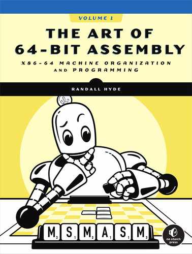
Without question, the most important data structure used by the x86-64 microprocessor is the byte, which consists of 8 bits. Main memory and I/O addresses on the x86-64 are all byte addresses. This means that the smallest item that can be individually accessed by an x86-64 program is an 8-bit value. To access anything smaller requires that we read the byte containing the data and eliminate the unwanted bits. The bits in a byte are normally numbered from 0 to 7, as shown in Figure 2-1.

Figure 2-1: Bit numbering
Bit 0 is the LO bit, or least significant bit, and bit 7 is the HO bit, or most significant bit of the byte. We’ll refer to all other bits by their number.
A byte contains exactly two nibbles (see Figure 2-2).
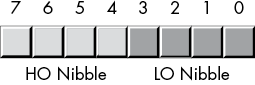
Figure 2-2: The two nibbles in a byte
Bits 0 to 3 compose the low-order nibble, and bits 4 to 7 form the high-order nibble. Because a byte contains exactly two nibbles, byte values require two hexadecimal digits.
Because a byte contains 8 bits, it can represent 28 (256) different values. Generally, we’ll use a byte to represent numeric values in the range 0 through 255, signed numbers in the range –128 through +127 (see “Signed and Unsigned Numbers” on page 62), ASCII IBM character codes, and other special data types requiring no more than 256 different values. Many data types have fewer than 256 items, so 8 bits are usually sufficient.
Because the x86-64 is a byte-addressable machine, it’s more efficient to manipulate a whole byte than an individual bit or nibble. So it’s more efficient to use a whole byte to represent data types that require no more than 256 items, even if fewer than 8 bits would suffice.
Probably the most important use for a byte is holding a character value. Characters typed at the keyboard, displayed on the screen, and printed on the printer all have numeric values. To communicate with the rest of the world, PCs typically use a variant of the ASCII character set or the Unicode character set. The ASCII character set has 128 defined codes.
Bytes are also the smallest variable you can create in a MASM program. To create an arbitrary byte variable, you should use the byte data type, as follows:
         .data
byteVar  byte ?
The byte data type is a partially untyped data type. The only type information associated with a byte object is its size (1 byte).2 You may store any 8-bit value (small signed integers, small unsigned integers, characters, and the like) into a byte variable. It is up to you to keep track of the type of object you’ve put into a byte variable.
2.4.4 Words
A word is a group of 16 bits. We’ll number the bits in a word from 0 to 15, as Figure 2-3 shows. Like the byte, bit 0 is the low-order bit. For words, bit 15 is the high-order bit. When referencing the other bits in a word, we’ll use their bit position number.
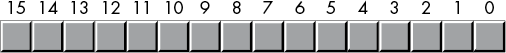
Figure 2-3: Bit numbers in a word
A word contains exactly 2 bytes (and, therefore, four nibbles). Bits 0 to 7 form the low-order byte, and bits 8 to 15 form the high-order byte (see Figures 2-4 and 2-5).
Figure 2-4: The 2 bytes in a word
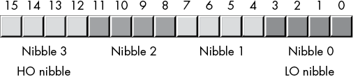
Figure 2-5: Nibbles in a word
With 16 bits, you can represent 216 (65,536) values. These could be the values in the range 0 to 65,535 or, as is usually the case, the signed values –32,768 to +32,767, or any other data type with no more than 65,536 values.
The three major uses for words are short signed integer values, short unsigned integer values, and Unicode characters. Unsigned numeric values are represented by the binary value corresponding to the bits in the word. Signed numeric values use the two’s complement form for numeric values (see “Sign Extension and Zero Extension” on page 67). As Unicode characters, words can represent up to 65,536 characters, allowing the use of non-Roman character sets in a computer program. Unicode is an international standard, like ASCII, that allows computers to process non-Roman characters such as Kanji, Greek, and Russian characters.
As with bytes, you can also create word variables in a MASM program. To create an arbitrary word variable, use the word data type as follows:
         .data
w        word  ?
2.4.5 Double Words
A double word is exactly what its name indicates: a pair of words. Therefore, a double-word quantity is 32 bits long, as shown in Figure 2-6.

Figure 2-6: Bit numbers in a double word
Naturally, this double word can be divided into a high-order word and a low-order word, 4 bytes, or eight different nibbles (see Figure 2-7).
Double words (dwords) can represent all kinds of things. A common item you will represent with a double word is a 32-bit integer value (which allows unsigned numbers in the range 0 to 4,294,967,295 or signed numbers in the range –2,147,483,648 to 2,147,483,647). 32-bit floating-point values also fit into a double word.
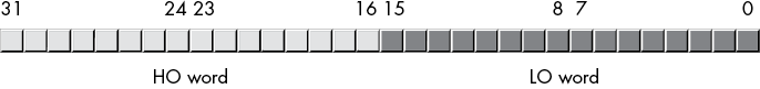

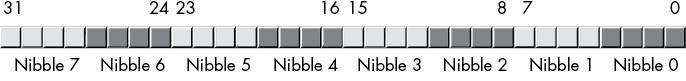
Figure 2-7: Nibbles, bytes, and words in a double word
You can create an arbitrary double-word variable by using the dword data type, as the following example demonstrates:
      .data
d     dword  ?
2.4.6 Quad Words and Octal Words
Quad-word (64-bit) values are also important because 64-bit integers, pointers, and certain floating-point data types require 64 bits. Likewise, the SSE/MMX instruction set of modern x86-64 processors can manipulate 64-bit values. In a similar vein, octal-word (128-bit) values are important because the AVX/SSE instruction set can manipulate 128-bit values. MASM allows the declaration of 64- and 128-bit values by using the qword and oword types, as follows:
      .data
o     oword ?
q     qword ?
You may not directly manipulate 128-bit integer objects using standard instructions like mov, add, and sub because the standard x86-64 integer registers process only 64 bits at a time. In Chapter 8, you will see how to manipulate these extended-precision values; Chapter 11 describes how to directly manipulate oword values by using SIMD instructions.
2.5 Logical Operations on Bits
We’ll do four primary logical operations (Boolean functions) with hexadecimal and binary numbers: AND, OR, XOR (exclusive-or), and NOT.
2.5.1 The AND Operation
The logical AND operation is a dyadic operation (meaning it accepts exactly two operands).3 These operands are individual binary bits. The AND operation is shown here:
0 and 0 = 0
0 and 1 = 0
1 and 0 = 0
1 and 1 = 1
A compact way to represent the logical AND operation is with a truth table. A truth table takes the form shown in Table 2-2.
Table 2-2: AND Truth Table
| AND | 0 | 1 |
| 0 | 0 | 0 |
| 1 | 0 | 1 |
This is just like the multiplication tables you’ve encountered in school. The values in the left column correspond to the left operand of the AND operation. The values in the top row correspond to the right operand of the AND operation. The value located at the intersection of the row and column (for a particular pair of input values) is the result of logically ANDing those two values together.
In English, the logical AND operation is, “If the first operand is 1 and the second operand is 1, the result is 1; otherwise, the result is 0.” We could also state this as, “If either or both operands are 0, the result is 0.”
You can use the logical AND operation to force a 0 result: if one of the operands is 0, the result is always 0 regardless of the other operand. In Table 2-2, for example, the row labeled with a 0 input contains only 0s, and the column labeled with a 0 contains only 0s. Conversely, if one operand contains a 1, the result is exactly the value of the second operand. These results of the AND operation are important, particularly when we want to force bits to 0. We will investigate these uses of the logical AND operation in the next section.
2.5.2 The OR Operation
The logical OR operation is also a dyadic operation. Its definition is as follows:
0 or 0 = 0
0 or 1 = 1
1 or 0 = 1
1 or 1 = 1
Table 2-3 shows the truth table for the OR operation.
Table 2-3: OR Truth Table
| OR | 0 | 1 |
| 0 | 0 | 1 |
| 1 | 1 | 1 |
Colloquially, the logical OR operation is, “If the first operand or the second operand (or both) is 1, the result is 1; otherwise, the result is 0.” This is also known as the inclusive-or operation.
If one of the operands to the logical OR operation is a 1, the result is always 1 regardless of the second operand’s value. If one operand is 0, the result is always the value of the second operand. Like the logical AND operation, this is an important side effect of the logical OR operation that will prove quite useful.
Note that there is a difference between this form of the inclusive logical OR operation and the standard English meaning. Consider the sentence “I am going to the store or I am going to the park.” Such a statement implies that the speaker is going to the store or to the park, but not to both places. Therefore, the English version of logical OR is slightly different from the inclusive-or operation; indeed, this is the definition of the exclusive-or operation.
2.5.3 The XOR Operation
The logical XOR (exclusive-or) operation is also a dyadic operation. Its definition follows:
0 xor 0 = 0
0 xor 1 = 1
1 xor 0 = 1
1 xor 1 = 0
Table 2-4 shows the truth table for the XOR operation.
Table 2-4: XOR Truth Table
| XOR | 0 | 1 |
| 0 | 0 | 1 |
| 1 | 1 | 0 |
In English, the logical XOR operation is, “If the first operand or the second operand, but not both, is 1, the result is 1; otherwise, the result is 0.” The exclusive-or operation is closer to the English meaning of the word or than is the logical OR operation.
If one of the operands to the logical exclusive-or operation is a 1, the result is always the inverse of the other operand; that is, if one operand is 1, the result is 0 if the other operand is 1, and the result is 1 if the other operand is 0. If the first operand contains a 0, the result is exactly the value of the second operand. This feature lets you selectively invert bits in a bit string.
2.5.4 The NOT Operation
The logical NOT operation is a monadic operation (meaning it accepts only one operand):
not 0 = 1
not 1 = 0
The truth table for the NOT operation appears in Table 2-5.
Table 2-5: NOT Truth Table
| NOT | 0 | 1 |
| 1 | 0 |
2.6 Logical Operations on Binary Numbers and Bit Strings
The previous section defines the logical functions for single-bit operands. Because the x86-64 uses groups of 8, 16, 32, 64, or more bits,4 we need to extend the definition of these functions to deal with more than 2 bits.
Logical functions on the x86-64 operate on a bit-by-bit (or bitwise) basis. Given two values, these functions operate on bit 0 of each value, producing bit 0 of the result; then they operate on bit 1 of the input values, producing bit 1 of the result, and so on. For example, if you want to compute the logical AND of the following two 8-bit numbers, you would perform the logical AND operation on each column independently of the others:
1011_0101b
1110_1110b
----------
1010_0100b
You may apply this bit-by-bit calculation to the other logical functions as well.
To perform a logical operation on two hexadecimal numbers, you should convert them to binary first.
The ability to force bits to 0 or 1 by using the logical AND/OR operations and the ability to invert bits using the logical XOR operation are very important when working with strings of bits (for example, binary numbers). These operations let you selectively manipulate certain bits within a bit string while leaving other bits unaffected.
For example, if you have an 8-bit binary value X and you want to guarantee that bits 4 to 7 contain 0s, you could logically AND the value X with the binary value 0000_1111b. This bitwise logical AND operation would force the HO 4 bits to 0 and pass the LO 4 bits of X unchanged. Likewise, you could force the LO bit of X to 1 and invert bit 2 of X by logically ORing X with 0000_0001b and logically XORing X with 0000_0100b, respectively.
Using the logical AND, OR, and XOR operations to manipulate bit strings in this fashion is known as masking bit strings. We use the term masking because we can use certain values (1 for AND, 0 for OR/XOR) to mask out or mask in certain bits from the operation when forcing bits to 0, 1, or their inverse.
The x86-64 CPUs support four instructions that apply these bitwise logical operations to their operands. The instructions are and, or, xor, and not. The and, or, and xor instructions use the same syntax as the add and sub instructions:
and  dest, source
or   dest, source
xor  dest, source
These operands have the same limitations as the add operands. Specifically, the source operand has to be a constant, memory, or register operand, and the dest operand must be a memory or register operand. Also, the operands must be the same size and cannot both be memory operands. If the destination operand is 64 bits and the source operand is a constant, that constant is limited to 32 bits (or fewer), and the CPU will sign-extend the value to 64 bits (see “Sign Extension and Zero Extension” on page 67).
These instructions compute the obvious bitwise logical operation via the following equation:
dest = dest operator sourceThe x86-64 logical not instruction, because it has only a single operand, uses a slightly different syntax. This instruction takes the following form:
not dest This instruction computes the following result:
dest = not(dest)The dest operand must be a register or memory operand. This instruction inverts all the bits in the specified destination operand.
The program in Listing 2-2 inputs two hexadecimal values from the user and calculates their logical and, or, xor, and not.
; Listing 2-2

; Demonstrate AND, OR, XOR, and NOT logical instructions.

            option  casemap:none

nl          =       10  ; ASCII code for newline

             .data
leftOp       dword   0f0f0f0fh
rightOp1     dword   0f0f0f0f0h
rightOp2     dword   12345678h

titleStr     byte   'Listing 2-2', 0

fmtStr1      byte   "%lx AND %lx = %lx", nl, 0
fmtStr2      byte   "%lx OR  %lx = %lx", nl, 0
fmtStr3      byte   "%lx XOR %lx = %lx", nl, 0
fmtStr4      byte   "NOT %lx = %lx", nl, 0

            .code
            externdef   printf:proc

; Return program title to C++ program:

            public getTitle
getTitle    proc

;  Load address of "titleStr" into the RAX register (RAX holds the
;  function return result) and return back to the caller:

            lea rax, titleStr
            ret
getTitle    endp

; Here is the "asmMain" function.

            public  asmMain
asmMain     proc

; "Magic" instruction offered without explanation at this point:

            sub     rsp, 56

; Demonstrate the AND instruction:

            lea     rcx, fmtStr1
            mov     edx, leftOp
            mov     r8d, rightOp1
            mov     r9d, edx  ; Compute leftOp
            and     r9d, r8d  ; AND rightOp1
            call    printf

            lea     rcx, fmtStr1
            mov     edx, leftOp
            mov     r8d, rightOp2
            mov     r9d, r8d
            and     r9d, edx
            call    printf

; Demonstrate the OR instruction:

            lea     rcx, fmtStr2
            mov     edx, leftOp
            mov     r8d, rightOp1
            mov     r9d, edx  ; Compute leftOp
            or      r9d, r8d  ; OR rightOp1
            call    printf

            lea     rcx, fmtStr2
            mov     edx, leftOp
            mov     r8d, rightOp2
            mov     r9d, r8d
            or      r9d, edx
            call    printf

; Demonstrate the XOR instruction:

            lea     rcx, fmtStr3
            mov     edx, leftOp
            mov     r8d, rightOp1
            mov     r9d, edx  ; Compute leftOp
            xor     r9d, r8d  ; XOR rightOp1
            call    printf

            lea     rcx, fmtStr3
            mov     edx, leftOp
            mov     r8d, rightOp2
            mov     r9d, r8d
            xor     r9d, edx
            call    printf

; Demonstrate the NOT instruction:

            lea     rcx, fmtStr4
            mov     edx, leftOp
            mov     r8d, edx  ; Compute not leftOp
            not     r8d
            call    printf

            lea     rcx, fmtStr4
            mov     edx, rightOp1
            mov     r8d, edx  ; Compute not rightOp1
            not     r8d
            call    printf

            lea     rcx, fmtStr4
            mov     edx, rightOp2
            mov     r8d, edx  ; Compute not rightOp2
            not     r8d
            call    printf

; Another "magic" instruction that undoes the effect of the previous
; one before this procedure returns to its caller.

            add     rsp, 56

            ret     ; Returns to caller

asmMain     endp
            end
Listing 2-2: and, or, xor, and not example
Here’s the result of building and running this code:
C:MASM64>build  listing2-2

C:MASM64>ml64 /nologo /c /Zi /Cp  listing2-2.asm
 Assembling: listing2-2.asm

C:MASM64>cl /nologo /O2 /Zi /utf-8 /Fe listing2-2.exe c.cpp  listing2-2.obj
c.cpp

C:MASM64> listing2-2
Calling Listing 2-2:
f0f0f0f AND f0f0f0f0 = 0
f0f0f0f AND 12345678 = 2040608
f0f0f0f OR  f0f0f0f0 = ffffffff
f0f0f0f OR  12345678 = 1f3f5f7f
f0f0f0f XOR f0f0f0f0 = ffffffff
f0f0f0f XOR 12345678 = 1d3b5977
NOT f0f0f0f = f0f0f0f0
NOT f0f0f0f0 = f0f0f0f
NOT 12345678 = edcba987
Listing 2-2 terminated
By the way, you will often see the following “magic” instruction:
xor reg, regXORing a register with itself sets that register to 0. Except for 8-bit registers, the xor instruction is usually more efficient than moving the immediate constant into the register. Consider the following:
xor eax, eax  ; Just 2 bytes long in machine code
mov eax, 0    ; Depending on register, often 6 bytes long
The savings are even greater when dealing with 64-bit registers (as the immediate constant 0 is 8 bytes long by itself).
2.7 Signed and Unsigned Numbers
Thus far, we’ve treated binary numbers as unsigned values. The binary number . . . 00000 represents 0, . . . 00001 represents 1, . . . 00010 represents 2, and so on toward infinity. With n bits, we can represent 2n unsigned numbers. What about negative numbers? If we assign half of the possible combinations to the negative values, and half to the positive values and 0, with n bits we can represent the signed values in the range –2n-1 to +2n-1 –1. So we can represent the negative values –128 to –1 and the non-negative values 0 to 127 with a single 8-bit byte. With a 16-bit word, we can represent values in the range –32,768 to +32,767. With a 32-bit double word, we can represent values in the range –2,147,483,648 to +2,147,483,647.
In mathematics (and computer science), the complement method encodes negative and non-negative (positive plus zero) numbers into two equal sets in such a way that they can use the same algorithm (or hardware) to perform addition and produce the correct result regardless of the sign.
The x86-64 microprocessor uses the two’s complement notation to represent signed numbers. In this system, the HO bit of a number is a sign bit (dividing the integers into two equal sets). If the sign bit is 0, the number is positive (or zero); if the sign bit is 1, the number is negative (taking a complement form, which I’ll describe in a moment). Following are some examples.
For 16-bit numbers:
- 8000h is negative because the HO bit is 1.
- 100h is positive because the HO bit is 0.
- 7FFFh is positive.
- 0FFFFh is negative.
- 0FFFh is positive.
If the HO bit is 0, the number is positive (or 0) and uses the standard binary format. If the HO bit is 1, the number is negative and uses the two’s complement form (which is the magic form that supports addition of negative and non-negative numbers with no special hardware).
To convert a positive number to its negative, two’s complement form, you use the following algorithm:
- Invert all the bits in the number; that is, apply the logical NOT function.
- Add 1 to the inverted result and ignore any carry out of the HO bit.
This produces a bit pattern that satisfies the mathematical definition of the complement form. In particular, adding negative and non-negative numbers using this form produces the expected result.
For example, to compute the 8-bit equivalent of –5:
- 0000_0101b 5 (in binary).
- 1111_1010b Invert all the bits.
- 1111_1011b Add 1 to obtain result.
If we take –5 and perform the two’s complement operation on it, we get our original value, 0000_0101b, back again:
- 1111_1011b Two’s complement for –5.
- 0000_0100b Invert all the bits.
- 0000_0101b Add 1 to obtain result (+5).
Note that if we add +5 and –5 together (ignoring any carry out of the HO bit), we get the expected result of 0:
      1111_1011b         Two's complement for -5
    + 0000_0101b         Invert all the bits and add 1
      ----------
  (1) 0000_0000b         Sum is zero, if we ignore carry
The following examples provide some positive and negative 16-bit signed values:
- 7FFFh: +32767, the largest 16-bit positive number
- 8000h: –32768, the smallest 16-bit negative number
- 4000h: +16384
To convert the preceding numbers to their negative counterpart (that is, to negate them), do the following:
7FFFh:      0111_1111_1111_1111b   +32,767
            1000_0000_0000_0000b   Invert all the bits (8000h)
            1000_0000_0000_0001b   Add 1 (8001h or -32,767)

4000h:      0100_0000_0000_0000b   16,384
            1011_1111_1111_1111b   Invert all the bits (0BFFFh)
            1100_0000_0000_0000b   Add 1 (0C000h or -16,384)

8000h:      1000_0000_0000_0000b   -32,768
            0111_1111_1111_1111b   Invert all the bits (7FFFh)
            1000_0000_0000_0000b   Add one (8000h or -32,768)
8000h inverted becomes 7FFFh. After adding 1, we obtain 8000h! Wait, what’s going on here? – (–32,768) is –32,768? Of course not. But the value +32,768 cannot be represented with a 16-bit signed number, so we cannot negate the smallest negative value.
Usually, you will not need to perform the two’s complement operation by hand. The x86-64 microprocessor provides an instruction, neg (negate), that performs this operation for you:
neg dest This instruction computes dest = -dest; and the operand must be a memory location or a register. neg operates on byte-, word-, dword-, and qword-sized objects. Because this is a signed integer operation, it only makes sense to operate on signed integer values. The program in Listing 2-3 demonstrates the two’s complement operation and the neg instruction on signed 8-bit integer values.
; Listing 2-3

; Demonstrate two's complement operation and input of numeric values.

        option  casemap:none

nl       =      10  ; ASCII code for newline
maxLen   =      256

         .data
titleStr byte   'Listing 2-3', 0

prompt1  byte   "Enter an integer between 0 and 127:", 0
fmtStr1  byte   "Value in hexadecimal: %x", nl, 0
fmtStr2  byte   "Invert all the bits (hexadecimal): %x", nl, 0
fmtStr3  byte   "Add 1 (hexadecimal): %x", nl, 0
fmtStr4  byte   "Output as signed integer: %d", nl, 0
fmtStr5  byte   "Using neg instruction: %d", nl, 0

intValue sqword ?
input    byte   maxLen dup (?)

            .code
            externdef printf:proc
            externdef atoi:proc
            externdef readLine:proc

; Return program title to C++ program:

            public getTitle
getTitle    proc
            lea rax, titleStr
            ret
getTitle    endp

; Here is the "asmMain" function.

            public  asmMain
asmMain     proc

; "Magic" instruction offered without explanation at this point:

            sub     rsp, 56

; Read an unsigned integer from the user: This code will blindly
; assume that the user's input was correct. The atoi function returns
; zero if there was some sort of error on the user input. Later
; chapters in Ao64A will describe how to check for errors from the
; user.

            lea     rcx, prompt1
            call    printf

            lea     rcx, input
            mov     rdx, maxLen
            call    readLine

; Call C stdlib atoi function.

; i = atoi(str)

            lea     rcx, input
            call    atoi
            and     rax, 0ffh      ; Only keep LO 8 bits
            mov     intValue, rax

; Print the input value (in decimal) as a hexadecimal number:

            lea     rcx, fmtStr1
            mov     rdx, rax
            call    printf

; Perform the two's complement operation on the input number.
; Begin by inverting all the bits (just work with a byte here).

            mov     rdx, intValue
            not     dl             ; Only work with 8-bit values!
            lea     rcx, fmtStr2
            call    printf

; Invert all the bits and add 1 (still working with just a byte).

            mov     rdx, intValue
            not     rdx
            add     rdx, 1
            and     rdx, 0ffh      ; Only keep LO eight bits
            lea     rcx, fmtStr3
            call    printf

; Negate the value and print as a signed integer (work with a full
; integer here, because C++ %d format specifier expects a 32-bit
; integer). HO 32 bits of RDX get ignored by C++.

            mov     rdx, intValue
            not     rdx
            add     rdx, 1
            lea     rcx, fmtStr4
            call    printf

; Negate the value using the neg instruction.

            mov     rdx, intValue
            neg     rdx
            lea     rcx, fmtStr5
            call    printf

; Another "magic" instruction that undoes the effect of the previous
; one before this procedure returns to its caller.

            add     rsp, 56
            ret     ; Returns to caller
asmMain     endp
            end
Listing 2-3: Two’s complement example
The following commands build and run the program in Listing 2-3:
C:>build  listing2-3

C:>echo off
 Assembling: listing2-3.asm
c.cpp

C:> listing2-3
Calling Listing 2-3:
Enter an integer between 0 and 127:123
Value in hexadecimal: 7b
Invert all the bits (hexadecimal): 84
Add 1 (hexadecimal): 85
Output as signed integer: -123
Using neg instruction: -123
Listing 2-3 terminated
Beyond the two’s complement operation (both by inversion/add 1 and using the neg instruction), this program demonstrates one new feature: user numeric input. Numeric input is accomplished by reading an input string from the user (using the readLine() function that is part of the c.cpp source file) and then calling the C Standard Library atoi() function. This function requires a single parameter (passed in RCX) that points to a string containing an integer value. It translates that string to the corresponding integer and returns the integer value in RAX.5
2.8 Sign Extension and Zero Extension
Converting an 8-bit two’s complement value to 16 bits, and conversely converting a 16-bit value to 8 bits, can be accomplished via sign extension and contraction operations.
To extend a signed value from a certain number of bits to a greater number of bits, copy the sign bit into all the additional bits in the new format. For example, to sign-extend an 8-bit number to a 16-bit number, copy bit 7 of the 8-bit number into bits 8 to 15 of the 16-bit number. To sign-extend a 16-bit number to a double word, copy bit 15 into bits 16 to 31 of the double word.
You must use sign extension when manipulating signed values of varying lengths. For example, to add a byte quantity to a word quantity, you must sign-extend the byte quantity to a word before adding the two values. Other operations (multiplication and division, in particular) may require a sign extension to 32 bits; see Table 2-6.
Table 2-6: Sign Extension
| 8 Bits | 16 Bits | 32 Bits |
| 80h | 0FF80h | 0FFFFFF80h |
| 28h | 0028h | 00000028h |
| 9Ah | 0FF9Ah | 0FFFFFF9Ah |
| 7Fh | 007Fh | 0000007Fh |
| 1020h | 00001020h | |
| 8086h | 0FFFF8086h |
To extend an unsigned value to a larger one, you must zero-extend the value, as shown in Table 2-7. Zero extension is easy—just store a 0 into the HO byte(s) of the larger operand. For example, to zero-extend the 8-bit value 82h to 16 bits, you prepend a 0 to the HO byte, yielding 0082h.
Table 2-7: Zero Extension
| 8 Bits | 16 Bits | 32 Bits |
| 80h | 0080h | 00000080h |
| 28h | 0028h | 00000028h |
| 9Ah | 009Ah | 0000009Ah |
| 7Fh | 007Fh | 0000007Fh |
| 1020h | 00001020h | |
| 8086h | 00008086h |
2.9 Sign Contraction and Saturation
Sign contraction, converting a value with a certain number of bits to the identical value with a fewer number of bits, is a little more troublesome. Given an n-bit number, you cannot always convert it to an m-bit number if m < n. For example, consider the value –448. As a 16-bit signed number, its hexadecimal representation is 0FE40h. The magnitude of this number is too large for an 8-bit value, so you cannot sign-contract it to 8 bits (doing so would create an overflow condition).
To properly sign-contract a value, the HO bytes to discard must all contain either 0 or 0FFh, and the HO bit of your resulting value must match every bit you’ve removed from the number. Here are some examples (16 bits to 8 bits):
- 0FF80h can be sign-contracted to 80h.
- 0040h can be sign-contracted to 40h.
- 0FE40h cannot be sign-contracted to 8 bits.
- 0100h cannot be sign-contracted to 8 bits.
If you must convert a larger object to a smaller object, and you’re willing to live with loss of precision, you can use saturation. To convert a value via saturation, you copy the larger value to the smaller value if it is not outside the range of the smaller object. If the larger value is outside the range of the smaller value, you clip the value by setting it to the largest (or smallest) value within the range of the smaller object.
For example, when converting a 16-bit signed integer to an 8-bit signed integer, if the 16-bit value is in the range –128 to +127, you copy the LO byte of the 16-bit object to the 8-bit object. If the 16-bit signed value is greater than +127, then you clip the value to +127 and store +127 into the 8-bit object. Likewise, if the value is less than –128, you clip the final 8-bit object to –128.
Although clipping the value to the limits of the smaller object results in loss of precision, sometimes this is acceptable because the alternative is to raise an exception or otherwise reject the calculation. For many applications, such as audio or video processing, the clipped result is still recognizable, so this is a reasonable conversion.
2.10 Brief Detour: An Introduction to Control Transfer Instructions
The assembly language examples thus far have limped along without making use of conditional execution (that is, the ability to make decisions while executing code). Indeed, except for the call and ret instructions, you haven’t seen any way to affect the straight-line execution of assembly code.
However, this book is rapidly approaching the point where meaningful examples require the ability to conditionally execute different sections of code. This section provides a brief introduction to the subject of conditional execution and transferring control to other sections of your program.
2.10.1 The jmp Instruction
Perhaps the best place to start is with a discussion of the x86-64 unconditional transfer-of-control instruction—the jmp instruction. The jmp instruction takes several forms, but the most common form is
jmp statement_labelwhere statement_label is an identifier attached to a machine instruction in your .code section. The jmp instruction immediately transfers control to the statement prefaced by the label. This is semantically equivalent to a goto statement in an HLL.
Here is an example of a statement label in front of a mov instruction:
stmtLbl: mov eax, 55Like all MASM symbols, statement labels have two major attributes associated with them: an address (which is the memory address of the machine instruction following the label) and a type. The type is label, which is the same type as a proc directive’s identifier.
Statement labels don’t have to be on the same physical source line as a machine instruction. Consider the following example:
anotherLabel:
   mov eax, 55
This example is semantically equivalent to the previous one. The value (address) bound to anotherLabel is the address of the machine instruction following the label. In this case, it’s still the mov instruction even though that mov instruction appears on the next line (it still follows the label without any other MASM statements that would generate code occurring between the label and the mov statement).
Technically, you could also jump to a proc label instead of a statement label. However, the jmp instruction does not set up a return address, so if the procedure executes a ret instruction, the return location may be undefined. (Chapter 5 explores return addresses in greater detail.)
2.10.2 The Conditional Jump Instructions
Although the common form of the jmp instruction is indispensable in assembly language programs, it doesn’t provide any ability to conditionally execute different sections of code—hence the name unconditional jump.6 Fortunately, the x86-64 CPUs provide a wide array of conditional jump instructions that, as their name suggests, allow conditional execution of code.
These instructions test the condition code bits (see “An Introduction to the Intel x86-64 CPU Family” in Chapter 1) in the FLAGS register to determine whether a branch should be taken. There are four condition code bits in the FLAGs register that these conditional jump instructions test: the carry, sign, overflow, and zero flags.7
The x86-64 CPUs provide eight instructions that test each of these four flags (see Table 2-8). The basic operation of the conditional jump instructions is that they test a flag to see if it is set (1) or clear (0) and branch to a target label if the test succeeds. If the test fails, the program continues execution with the next instruction following the conditional jump instruction.
Table 2-8: Conditional Jump Instructions That Test the Condition Code Flags
| Instruction | Explanation |
jc label |
Jump if carry set. Jump to label if the carry flag is set (1); fall through if carry is clear (0). |
jnc label |
Jump if no carry. Jump to label if the carry flag is clear (0); fall through if carry is set (1). |
jo label |
Jump if overflow. Jump to label if the overflow flag is set (1); fall through if overflow is clear (0). |
jno label |
Jump if no overflow. Jump to label if the overflow flag is clear (0); fall through if overflow is set (1). |
js label |
Jump if sign (negative). Jump to label if the sign flag is set (1); fall through if sign is clear (0). |
jns label |
Jump if not sign. Jump to label if the sign flag is clear (0); fall through if sign is set (1). |
jz label |
Jump if zero. Jump to label if the zero flag is set (1); fall through if zero is clear (0). |
jnz label |
Jump if not zero. Jump to label if the zero flag is clear (0); fall through if zero is set (1). |
To use a conditional jump instruction, you must first execute an instruction that affects one (or more) of the condition code flags. For example, an unsigned arithmetic overflow will set the carry flag (and likewise, if overflow does not occur, the carry flag will be clear). Therefore, you could use the jc and jnc instructions after an add instruction to see if an (unsigned) overflow occurred during the calculation. For example:
    mov eax, int32Var
    add eax, anotherVar
    jc  overflowOccurred

; Continue down here if the addition did not
; produce an overflow.

    .
    .
    .

overflowOccurred:

; Execute this code if the sum of int32Var and anotherVar
; does not fit into 32 bits.
Not all instructions affect the flags. Of all the instructions we’ve looked at thus far (mov, add, sub, and, or, not, xor, and lea), only the add, sub, and, or, xor, and not instructions affect the flags. The add and sub instructions affect the flags as shown in Table 2-9.
Table 2-9: Flag Settings After Executing add or sub
| Flag | Explanation |
| Carry | Set if an unsigned overflow occurs (for example, adding the byte values 0FFh and 01h). Clear if no overflow occurs. Note that subtracting 1 from 0 will also clear the carry flag (that is, 0 – 1 is equivalent to 0 + (–1), and –1 is 0FFh in two’s complement form). |
| Overflow | Set if a signed overflow occurs (for example, adding the byte values 07Fh and 01h). Signed overflow occurs when the next-to-HO-bit overflows into the HO bit (for example, 7Fh becomes 80h, or 0FFh becomes 0, when dealing with byte-sized calculations). |
| Sign | The sign flag is set if the HO bit of the result is set. The sign flag is clear otherwise (that is, the sign flag reflects the state of the HO bit of the result). |
| Zero | The zero flag is set if the result of a computation produces 0; it is clear otherwise. |
The logical instructions (and, or, xor, and not) always clear the carry and overflow flags. They copy the HO bit of their result into the sign flag and set/clear the zero flag if they produce a zero/nonzero result.
In addition to the conditional jump instructions, the x86-64 CPUs also provide a set of conditional move instructions. Chapter 7 covers those instructions.
2.10.3 The cmp Instruction and Corresponding Conditional Jumps
The cmp (compare) instruction is probably the most useful instruction to execute prior to a conditional jump. The compare instruction has the same syntax as the sub instruction and, in fact, it also subtracts the second operand from the first operand and sets the condition code flags based on the result of the subtraction.8 But the cmp instruction doesn’t store the difference back into the first (destination) operand. The whole purpose of the cmp instruction is to set the condition code flags based on the result of the subtraction.
Though you could use the jc/jnc, jo/jno, js/jns, and jz/jnz instructions immediately after a cmp instruction (to test how cmp has set the individual flags), the flag names don’t really mean much in the context of the cmp instruction. Logically, when you see the following instruction (note that the cmp instruction’s operand syntax is identical to the add, sub, and mov instructions),
cmp left_operand, right_operandyou read this instruction as “compare the left_operand to the right_operand.” Questions you would normally ask after such a comparison are as follows:
- Is the left_operand equal to the right_operand?
- Is the left_operand not equal to the right_operand?
- Is the left_operand less than the right_operand?
- Is the left_operand less than or equal to the right_operand?
- Is the left_operand greater than the right_operand?
- Is the left_operand greater than or equal to the right_operand?
The conditional jump instructions presented thus far don’t (intuitively) answer any of these questions.
The x86-64 CPUs provide an additional set of conditional jump instructions, shown in Table 2-10, that allow you to test for comparison conditions.
Table 2-10: Conditional Jump Instructions for Use After a cmp Instruction
| Instruction | Flags tested | Explanation |
je label |
ZF == 1 |
Jump if equal. Transfers control to target label if the left_operand is equal to the right_operand. This is a synonym for jz, as the zero flag will be set if the two operands are equal (their subtraction produces a 0 result in that case). |
jne label |
ZF == 0 |
Jump if not equal. Transfers control to target label if the left_operand is not equal to the right_operand. This is a synonym for jnz, as the zero flag will be clear if the two operands are not equal (their subtraction produces a nonzero result in that case). |
ja label |
CF == 0 and ZF == 0 |
Jump if above. Transfers control to target label if the unsigned left_operand is greater than the unsigned right_operand. |
jae label |
CF == 0 |
Jump if above or equal. Transfers control to target label if the unsigned left_operand is greater than or equal to the unsigned right_operand. This is a synonym for jnc, as it turns out that an unsigned overflow (well, underflow, actually) will not occur if the left_operand is greater than or equal to the right_operand. |
jb label |
CF == 1 |
Jump if below. Transfers control to target label if the unsigned left_operand is less than the unsigned right_operand. This is a synonym for jc, as it turns out that an unsigned overflow (well, underflow, actually) occurs if the left_operand is less than the right_operand. |
jbe label |
CF == 1 or ZF == 1 |
Jump if below or equal. Transfers control to target label if the unsigned left_operand is less than or equal to the unsigned right_operand. |
jg label |
SF == OF and ZF == 0 |
Jump if greater. Transfers control to target label if the signed left_operand is greater than the signed right_operand. |
jge label |
SF == OF |
Jump if greater or equal. Transfers control to target label if the signed left_operand is greater than or equal to the signed right_operand. |
jl label |
SF ≠ OF |
Jump if less. Transfers control to target label if the signed left_operand is less than the signed right_operand. |
jle label |
ZF == 1 or SF ≠ OF |
Jump if less or equal. Transfers control to target label if the signed left_operand is less than or equal to the signed right_operand. |
Perhaps the most important thing to note in Table 2-10 is that separate conditional jump instructions test for signed and unsigned comparisons. Consider the two byte values 0FFh and 01h. From an unsigned perspective, 0FFh is greater than 01h. However, when we treat these as signed numbers (using the two’s complement numbering system), 0FFh is actually –1, which is clearly less than 1. They have the same bit representations but two completely different comparison results when treating these values as signed or unsigned numbers.
2.10.4 Conditional Jump Synonyms
Some of the instructions are synonyms for other instructions. For example, jb and jc are the same instruction (that is, they have the same numeric machine code encoding). This is done for convenience and readability’s sake. After a cmp instruction, jb is much more meaningful than jc, for example. MASM defines several synonyms for various conditional branch instructions that make coding a little easier. Table 2-11 lists many of these synonyms.
Table 2-11: Conditional Jump Synonyms
| Instruction | Equivalents | Description |
ja |
jnbe |
Jump if above, jump if not below or equal. |
jae |
jnb, jnc |
Jump if above or equal, jump if not below, jump if no carry. |
jb |
jc, jnae |
Jump if below, jump if carry, jump if not above or equal. |
jbe |
jna |
Jump if below or equal, jump if not above. |
jc |
jb, jnae |
Jump if carry, jump if below, jump if not above or equal. |
je |
jz |
Jump if equal, jump if zero. |
jg |
jnle |
Jump if greater, jump if not less or equal. |
jge |
jnl |
Jump if greater or equal, jump if not less. |
jl |
jnge |
Jump if less, jump if not greater or equal. |
jle |
jng |
Jump if less or equal, jump if not greater. |
jna |
jbe |
Jump if not above, jump if below or equal. |
jnae |
jb, jc |
Jump if not above or equal, jump if below, jump if carry. |
jnb |
jae, jnc |
Jump if not below, jump if above or equal, jump if no carry. |
jnbe |
ja |
Jump if not below or equal, jump if above. |
jnc |
jnb, jae |
Jump if no carry, jump if no below, jump if above or equal. |
jne |
jnz |
Jump if not equal, jump if not zero. |
jng |
jle |
Jump if not greater, jump if less or equal. |
jnge |
jl |
Jump if not greater or equal, jump if less. |
jnl |
jge |
Jump if not less, jump if greater or equal. |
jnle |
jg |
Jump if not less or equal, jump if greater. |
jnz |
jne |
Jump if not zero, jump if not equal. |
jz |
je |
Jump if zero, jump if equal. |
There is a very important thing to note about the cmp instruction: it sets the flags only for integer comparisons (which will also cover characters and other types you can encode with an integer number). Specifically, it does not compare floating-point values and set the flags as appropriate for a floating-point comparison. To learn more about floating-point arithmetic (and comparisons), see “Floating-Point Arithmetic” in Chapter 6.
2.11 Shifts and Rotates
Another set of logical operations that apply to bit strings is the shift and rotate operations. These two categories can be further broken down into left shifts, left rotates, right shifts, and right rotates.
The shift-left operation moves each bit in a bit string one position to the left, as shown in Figure 2-8.
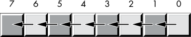
Figure 2-8: Shift-left operation
Bit 0 moves into bit position 1, the previous value in bit position 1 moves into bit position 2, and so on. We’ll shift a 0 into bit 0, and the previous value of the high-order bit will become the carry out of this operation.
The x86-64 provides a shift-left instruction, shl, that performs this useful operation. The syntax for the shl instruction is shown here:
shl dest, countThe count operand is either the CL register or a constant in the range 0 to n, where n is one less than the number of bits in the destination operand (for example, n = 7 for 8-bit operands, n = 15 for 16-bit operands, n = 31 for 32-bit operands, and n = 63 for 64-bit operands). The dest operand is a typical destination operand. It can be either a memory location or a register.
When the count operand is the constant 1, the shl instruction does the operation shown in Figure 2-9.
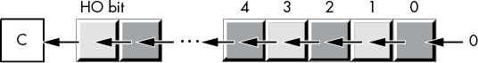
Figure 2-9: shl by 1 operation
In Figure 2-9, the C represents the carry flag—that is, the HO bit shifted out of the operand moves into the carry flag. Therefore, you can test for overflow after a shl dest, 1 instruction by testing the carry flag immediately after executing the instruction (for example, by using jc and jnc).
The shl instruction sets the zero flag based on the result (z=1 if the result is zero, z=0 otherwise). The shl instruction sets the sign flag if the HO bit of the result is 1. If the shift count is 1, then shl sets the overflow flag if the HO bit changes (that is, you shift a 0 into the HO bit when it was previously 1, or shift a 1 in when it was previously 0); the overflow flag is undefined for all other shift counts.
Shifting a value to the left one digit is the same thing as multiplying it by its radix (base). For example, shifting a decimal number one position to the left (adding a 0 to the right of the number) effectively multiplies it by 10 (the radix):
1234 shl 1 = 12340(shl 1 means shift one digit position to the left.)
Because the radix of a binary number is 2, shifting it left multiplies it by 2. If you shift a value to the left n times, you multiply that value by 2n.
A shift-right operation works the same way, except we’re moving the data in the opposite direction. For a byte value, bit 7 moves into bit 6, bit 6 moves into bit 5, bit 5 moves into bit 4, and so on. During a right shift, we’ll move a 0 into bit 7, and bit 0 will be the carry out of the operation (see Figure 2-10).

Figure 2-10: Shift-right operation
As you would probably expect, the x86-64 provides a shr instruction that will shift the bits to the right in a destination operand. The syntax is similar to that of the shl instruction:
shr dest, countThis instruction shifts a 0 into the HO bit of the destination operand; it shifts the other bits one place to the right (from a higher bit number to a lower bit number). Finally, bit 0 is shifted into the carry flag. If you specify a count of 1, the shr instruction does the operation shown in Figure 2-11.

Figure 2-11: shr by 1 operation
The shr instruction sets the zero flag based on the result (ZF=1 if the result is zero, ZF=0 otherwise). The shr instruction clears the sign flag (because the HO bit of the result is always 0). If the shift count is 1, shl sets the overflow flag if the HO bit changes (that is, you shift a 0 into the HO bit when it was previously 1, or shift a 1 in when it was previously 0); the overflow flag is undefined for all other shift counts.
Because a left shift is equivalent to a multiplication by 2, it should come as no surprise that a right shift is roughly comparable to a division by 2 (or, in general, a division by the radix of the number). If you perform n right shifts, you will divide that number by 2n.
However, a shift right is equivalent to only an unsigned division by 2. For example, if you shift the unsigned representation of 254 (0FEh) one place to the right, you get 127 (7Fh), exactly what you would expect. However, if you shift the two’s complement representation of –2 (0FEh) to the right one position, you get 127 (7Fh), which is not correct. This problem occurs because we’re shifting a 0 into bit 7. If bit 7 previously contained a 1, we’re changing it from a negative to a positive number. Not a good thing to do when dividing by 2.
To use the shift right as a division operator, we must define a third shift operation: arithmetic shift right.9 This works just like the normal shift-right operation (a logical shift right) except, instead of shifting a 0 into the high-order bit, an arithmetic shift-right operation copies the HO bit back into itself; that is, during the shift operation, it does not modify the HO bit, as Figure 2-12 shows.

Figure 2-12: Arithmetic shift-right operation
An arithmetic shift right generally produces the result you expect. For example, if you perform the arithmetic shift-right operation on –2 (0FEh), you get –1 (0FFh). However, this operation always rounds the numbers to the closest integer that is less than or equal to the actual result. For example, if you apply the arithmetic shift-right operation on –1 (0FFh), the result is –1, not 0. Because –1 is less than 0, the arithmetic shift-right operation rounds toward –1. This is not a bug in the arithmetic shift-right operation; it just uses a different (though valid) definition of integer division.
The x86-64 provides an arithmetic shift-right instruction, sar (shift arithmetic right). This instruction’s syntax is nearly identical to that of shl and shr:
sar dest, countThe usual limitations on the count and destination operands apply. This instruction operates as shown in Figure 2-13 if the count is 1.

Figure 2-13: sar dest, 1 operation
The sar instruction sets the zero flag based on the result (z=1 if the result is zero, and z=0 otherwise). The sar instruction sets the sign flag to the HO bit of the result. The overflow flag should always be clear after a sar instruction, as signed overflow is impossible with this operation.
The rotate-left and rotate-right operations behave like the shift-left and shift-right operations, except the bit shifted out from one end is shifted back in at the other end. Figure 2-14 diagrams these operations.


Figure 2-14: Rotate-left and rotate-right operations
The x86-64 provides rol (rotate left) and ror (rotate right) instructions that do these basic operations on their operands. The syntax for these two instructions is similar to the shift instructions:
rol dest, count
ror dest, count
If the shift count is 1, these two instructions copy the bit shifted out of the destination operand into the carry flag, as Figures 2-15 and 2-16 show.

Figure 2-15: rol dest, 1 operation

Figure 2-16: ror dest, 1 operation
Unlike the shift instructions, the rotate instructions do not affect the settings of the sign or zero flags. The OF flag is defined only for the 1-bit rotates; it is undefined in all other cases (except RCL and RCR instructions only: a zero-bit rotate does nothing—that is, it affects no flags). For left rotates, the OF flag is set to the exclusive-or of the original HO 2 bits. For right rotates, the OF flag is set to the exclusive-or of the HO 2 bits after the rotate.
It is often more convenient for the rotate operation to shift the output bit through the carry and to shift the previous carry value back into the input bit of the shift operation. The x86-64 rcl (rotate through carry left) and rcr (rotate through carry right) instructions achieve this for you. These instructions use the following syntax:
rcl dest, count
rcr dest, count
The count operand is either a constant or the CL register, and the dest operand is a memory location or register. The count operand must be a value that is less than the number of bits in the dest operand. For a count value of 1, these two instructions do the rotation shown in Figure 2-17.
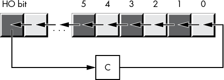

Figure 2-17: rcl dest, 1 and rcr dest, 1 operations
Unlike the shift instructions, the rotate-through-carry instructions do not affect the settings of the sign or zero flags. The OF flag is defined only for the 1-bit rotates. For left rotates, the OF flag is set if the original HO 2 bits change. For right rotates, the OF flag is set to the exclusive OR of the resultant HO 2 bits.
2.12 Bit Fields and Packed Data
Although the x86-64 operates most efficiently on byte, word, dword, and qword data types, occasionally you’ll need to work with a data type that uses a number of bits other than 8, 16, 32, or 64. You can also zero-extend a nonstandard data size to the next larger power of 2 (such as extending a 22-bit value to a 32-bit value). This turns out to be fast, but if you have a large array of such values, slightly more than 31 percent of the memory is going to waste (10 bits in every 32-bit value). However, suppose you were to repurpose those 10 bits for something else? By packing the separate 22-bit and 10-bit values into a single 32-bit value, you don’t waste any space.
For example, consider a date of the form 04/02/01. Representing this date requires three numeric values: month, day, and year values. Months, of course, take on the values 1 to 12. At least 4 bits (a maximum of 16 different values) are needed to represent the month. Days range from 1 to 31. So it will take 5 bits (a maximum of 32 different values) to represent the day entry. The year value, assuming that we’re working with values in the range 0 to 99, requires 7 bits (which can be used to represent up to 128 different values). So, 4 + 5 + 7 = 16 bits, or 2 bytes.
In other words, we can pack our date data into 2 bytes rather than the 3 that would be required if we used a separate byte for each of the month, day, and year values. This saves 1 byte of memory for each date stored, which could be a substantial savings if you need to store many dates. The bits could be arranged as shown in Figure 2-18.
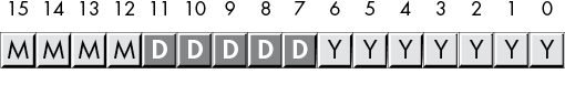
Figure 2-18: Short packed date format (2 bytes)
MMMM represents the 4 bits making up the month value, DDDDD represents the 5 bits making up the day, and YYYYYYY is the 7 bits composing the year. Each collection of bits representing a data item is a bit field. For example, April 2, 2001, would be represented as 4101h:
0100      00010   0000001      = 0100_0001_0000_0001b or 4101h
 4          2       01
Although packed values are space-efficient (that is, they make efficient use of memory), they are computationally inefficient (slow!). The reason? It takes extra instructions to unpack the data packed into the various bit fields. These extra instructions take additional time to execute (and additional bytes to hold the instructions); hence, you must carefully consider whether packed data fields will save you anything. The sample program in Listing 2-4 demonstrates the effort that must go into packing and unpacking this 16-bit date format.
; Listing 2-4

; Demonstrate packed data types.

        option  casemap:none

NULL    =       0
nl      =       10  ; ASCII code for newline
maxLen  =       256

; New data declaration section.
; .const holds data values for read-only constants.

            .const
ttlStr      byte    'Listing 2-4', 0
moPrompt    byte    'Enter current month: ', 0
dayPrompt   byte    'Enter current day: ', 0
yearPrompt  byte    'Enter current year '
            byte    '(last 2 digits only): ', 0

packed      byte    'Packed date is %04x', nl, 0
theDate     byte    'The date is %02d/%02d/%02d'
            byte    nl, 0

badDayStr   byte    'Bad day value was entered '
            byte    '(expected 1-31)', nl, 0

badMonthStr byte    'Bad month value was entered '
            byte    '(expected 1-12)', nl, 0
badYearStr  byte    'Bad year value was entered '
            byte    '(expected 00-99)', nl, 0

            .data
month       byte    ?
day         byte    ?
year        byte    ?
date        word    ?

input       byte    maxLen dup (?)

            .code
            externdef printf:proc
            externdef readLine:proc
            externdef atoi:proc

; Return program title to C++ program:

            public getTitle
getTitle    proc
            lea rax, ttlStr
            ret
getTitle    endp

; Here's a user-written function that reads a numeric value from the
; user:

; int readNum(char *prompt);

; A pointer to a string containing a prompt message is passed in the
; RCX register.

; This procedure prints the prompt, reads an input string from the
; user, then converts the input string to an integer and returns the
; integer value in RAX.

readNum     proc

; Must set up stack properly (using this "magic" instruction) before
; we can call any C/C++ functions:

            sub     rsp, 56

; Print the prompt message. Note that the prompt message was passed to
; this procedure in RCX, we're just passing it on to printf:

            call    printf

; Set up arguments for readLine and read a line of text from the user.
; Note that readLine returns NULL (0) in RAX if there was an error.

            lea     rcx, input
            mov     rdx, maxLen
            call    readLine

; Test for a bad input string:

            cmp     rax, NULL
            je      badInput

; Okay, good input at this point, try converting the string to an
; integer by calling atoi. The atoi function returns zero if there was
; an error, but zero is a perfectly fine return result, so we ignore
; errors.

            lea     rcx, input      ; Ptr to string
            call    atoi            ; Convert to integer

badInput:
            add     rsp, 56         ; Undo stack setup
            ret
readNum     endp

; Here is the "asmMain" function.

            public  asmMain
asmMain     proc
            sub     rsp, 56

; Read the date from the user. Begin by reading the month:

            lea     rcx, moPrompt
            call    readNum

; Verify the month is in the range 1..12:

            cmp     rax, 1
            jl      badMonth
            cmp     rax, 12
            jg      badMonth

; Good month, save it for now:

            mov     month, al       ; 1..12 fits in a byte

; Read the day:

            lea     rcx, dayPrompt
            call    readNum

; We'll be lazy here and verify only that the day is in the range
; 1..31.

            cmp     rax, 1
            jl      badDay
            cmp     rax, 31
            jg      badDay

; Good day, save it for now:

            mov     day, al         ; 1..31 fits in a byte

; Read the year:

            lea     rcx, yearPrompt
            call    readNum

; Verify that the year is in the range 0..99.

            cmp     rax, 0
            jl      badYear
            cmp     rax, 99
            jg      badYear

; Good year, save it for now:

            mov     year, al        ; 0..99 fits in a byte

; Pack the data into the following bits:

;  15 14 13 12 11 10  9  8  7  6  5  4  3  2  1  0
;   m  m  m  m  d  d  d  d  d  y  y  y  y  y  y  y

            movzx   ax, month
            shl     ax, 5
            or      al, day
            shl     ax, 7
            or      al, year
            mov     date, ax

; Print the packed date:

            lea     rcx, packed
            movzx   rdx, date
            call    printf

; Unpack the date and print it:

            movzx   rdx, date
            mov     r9, rdx
            and     r9, 7fh         ; Keep LO 7 bits (year)
            shr     rdx, 7          ; Get day in position
            mov     r8, rdx
            and     r8, 1fh         ; Keep LO 5 bits
            shr     rdx, 5          ; Get month in position
            lea     rcx, theDate
            call    printf

            jmp     allDone

; Come down here if a bad day was entered:

badDay:
            lea     rcx, badDayStr
            call    printf
            jmp     allDone

; Come down here if a bad month was entered:

badMonth:
            lea     rcx, badMonthStr
            call    printf
            jmp     allDone

; Come down here if a bad year was entered:

badYear:
            lea     rcx, badYearStr
            call    printf

allDone:
            add     rsp, 56
            ret     ; Returns to caller
asmMain     endp
            end
Listing 2-4: Packing and unpacking date data
Here’s the result of building and running this program:
C:>build  listing2-4

C:>echo off
 Assembling: listing2-4.asm
c.cpp

C:> listing2-4
Calling Listing 2-4:
Enter current month: 2
Enter current day: 4
Enter current year (last 2 digits only): 68
Packed date is 2244
The date is 02/04/68
Listing 2-4 terminated
Of course, having gone through the problems with Y2K (Year 2000),10 you know that using a date format that limits you to 100 years (or even 127 years) would be quite foolish. To future-proof the packed date format, we can extend it to 4 bytes packed into a double-word variable, as shown in Figure 2-19. (As you will see in Chapter 4, you should always try to create data objects whose length is an even power of 2—1 byte, 2 bytes, 4 bytes, 8 bytes, and so on—or you will pay a performance penalty.)

Figure 2-19: Long packed date format (4 bytes)
The Month and Day fields now consist of 8 bits each, so they can be extracted as a byte object from the double word. This leaves 16 bits for the year, with a range of 65,536 years. By rearranging the bits so the Year field is in the HO bit positions, the Month field is in the middle bit positions, and the Day field is in the LO bit positions, the long date format allows you to easily compare two dates to see if one date is less than, equal to, or greater than another date. Consider the following code:
    mov eax, Date1  ; Assume Date1 and Date2 are dword variables
    cmp eax, Date2  ; using the Long Packed Date format
    jna d1LEd2

            Do something if Date1 > Date2

d1LEd2:
Had you kept the different date fields in separate variables, or organized the fields differently, you would not have been able to compare Date1 and Date2 as easily as for the short packed data format. Therefore, this example demonstrates another reason for packing data even if you don’t realize any space savings—it can make certain computations more convenient or even more efficient (contrary to what normally happens when you pack data).
Examples of practical packed data types abound. You could pack eight Boolean values into a single byte, you could pack two BCD digits into a byte, and so on.
A classic example of packed data is the RFLAGS register. This register packs nine important Boolean objects (along with seven important system flags) into a single 16-bit register. You will commonly need to access many of these flags. You can test many of the condition code flags by using the conditional jump instructions and manipulate the individual bits in the FLAGS register with the instructions in Table 2-12 that directly affect certain flags.
Table 2-12: Instructions That Affect Certain Flags
| Instruction | Explanation |
cld |
Clears (sets to 0) the direction flag. |
std |
Sets (to 1) the direction flag. |
cli |
Clears the interrupt disable flag. |
sti |
Sets the interrupt disable flag. |
clc |
Clears the carry flag. |
stc |
Sets the carry flag. |
cmc |
Complements (inverts) the carry flag. |
sahf |
Stores the AH register into the LO 8 bits of the FLAGS register. (Warning: certain early x86-64 CPUs do not support this instruction.) |
lahf |
Loads AH from the LO 8 bits of the FLAGS register. (Warning: certain early x86-64 CPUs do not support this instruction.) |
The lahf and sahf instructions provide a convenient way to access the LO 8 bits of the FLAGS register as an 8-bit byte (rather than as eight separate 1-bit values). See Figure 2-20 for a layout of the FLAGS register.
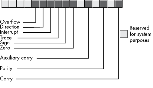
Figure 2-20: FLAGS register as packed Boolean data
The lahf (load AH with the LO eight bits of the FLAGS register) and the sahf (store AH into the LO byte of the RFLAGS register) use the following syntax:
        lahf
        sahf
2.13 IEEE Floating-Point Formats
When Intel planned to introduce a floating-point unit (the 8087 FPU) for its new 8086 microprocessor, it hired the best numerical analyst it could find to design a floating-point format. That person then hired two other experts in the field, and the three of them (William Kahan, Jerome Coonen, and Harold Stone) designed Intel’s floating-point format. They did such a good job designing the KCS Floating-Point Standard that the Institute of Electrical and Electronics Engineers (IEEE) adopted this format for its floating-point format.11
To handle a wide range of performance and accuracy requirements, Intel actually introduced three floating-point formats: single-precision, double-precision, and extended-precision. The single- and double-precision formats corresponded to C’s float and double types or FORTRAN’s real and double-precision types. The extended-precision format contains 16 extra bits that long chains of computations could use as guard bits before rounding down to a double-precision value when storing the result.
2.13.1 Single-Precision Format
The single-precision format uses a one’s complement 24-bit mantissa, an 8-bit excess-127 exponent, and a single sign bit. The mantissa usually represents a value from 1.0 to just under 2.0. The HO bit of the mantissa is always assumed to be 1 and represents a value just to the left of the binary point.12 The remaining 23 mantissa bits appear to the right of the binary point. Therefore, the mantissa represents the value:
1.mmmmmmm mmmmmmmmThe mmmm characters represent the 23 bits of the mantissa. Note that because the HO bit of the mantissa is always 1, the single-precision format doesn’t actually store this bit within the 32 bits of the floating-point number. This is known as an implied bit.
Because we are working with binary numbers, each position to the right of the binary point represents a value (0 or 1) times a successive negative power of 2. The implied 1 bit is always multiplied by 20, which is 1. This is why the mantissa is always greater than or equal to 1. Even if the other mantissa bits are all 0, the implied 1 bit always gives us the value 1.13 Of course, even if we had an almost infinite number of 1 bits after the binary point, they still would not add up to 2. This is why the mantissa can represent values in the range 1 to just under 2.
Although there is an infinite number of values between 1 and 2, we can represent only 8 million of them because we use a 23-bit mantissa (with the implied 24th bit always 1). This is the reason for inaccuracy in floating-point arithmetic—we are limited to a fixed number of bits in computations involving single-precision floating-point values.
The mantissa uses a one’s complement format rather than two’s complement to represent signed values. The 24-bit value of the mantissa is simply an unsigned binary number, and the sign bit determines whether that value is positive or negative. One’s complement numbers have the unusual property that there are two representations for 0 (with the sign bit set or clear). Generally, this is important only to the person designing the floating-point software or hardware system. We will assume that the value 0 always has the sign bit clear.
To represent values outside the range 1.0 to just under 2.0, the exponent portion of the floating-point format comes into play. The floating-point format raises 2 to the power specified by the exponent and then multiplies the mantissa by this value. The exponent is 8 bits and is stored in an excess-127 format. In excess-127 format, the exponent 0 is represented by the value 127 (7Fh), negative exponents are values in the range 0 to 126, and positive exponents are values in the range 128 to 255. To convert an exponent to excess-127 format, add 127 to the exponent value. The use of excess-127 format makes it easier to compare floating-point values. The single-precision floating-point format takes the form shown in Figure 2-21.
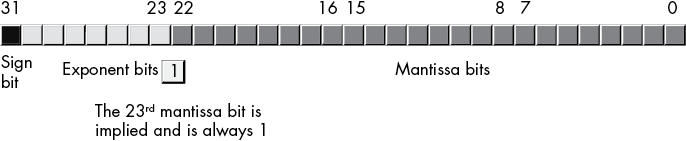
Figure 2-21: Single-precision (32-bit) floating-point format
With a 24-bit mantissa, you will get approximately six and a half (decimal) digits of precision (half a digit of precision means that the first six digits can all be in the range 0 to 9, but the seventh digit can be only in the range 0 to x, where x < 9 and is generally close to 5). With an 8-bit excess-127 exponent, the dynamic range14 of single-precision floating-point numbers is approximately 2±127, or about 10±38.
Although single-precision floating-point numbers are perfectly suitable for many applications, the precision and dynamic range are somewhat limited and unsuitable for many financial, scientific, and other applications. Furthermore, during long chains of computations, the limited accuracy of the single-precision format may introduce serious error.
2.13.2 Double-Precision Format
The double-precision format helps overcome the problems of single-precision floating-point. Using twice the space, the double-precision format has an 11-bit excess-1023 exponent and a 53-bit mantissa (with an implied HO bit of 1) plus a sign bit. This provides a dynamic range of about 10±308 and 14.5 digits of precision, sufficient for most applications. Double-precision floating-point values take the form shown in Figure 2-22.
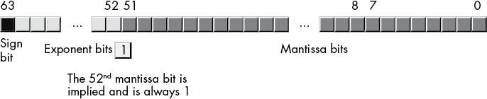
Figure 2-22: 64-bit double-precision floating-point format
2.13.3 Extended-Precision Format
To ensure accuracy during long chains of computations involving double-precision floating-point numbers, Intel designed the extended-precision format. It uses 80 bits. Twelve of the additional 16 bits are appended to the mantissa, and 4 of the additional bits are appended to the end of the exponent. Unlike the single- and double-precision values, the extended-precision format’s mantissa does not have an implied HO bit. Therefore, the extended-precision format provides a 64-bit mantissa, a 15-bit excess-16383 exponent, and a 1-bit sign. Figure 2-23 shows the format for the extended-precision floating-point value.
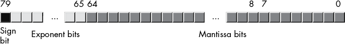
Figure 2-23: 80-bit extended-precision floating-point format
On the x86-64 FPU, all computations are done using the extended-precision format. Whenever you load a single- or double-precision value, the FPU automatically converts it to an extended-precision value. Likewise, when you store a single- or double-precision value to memory, the FPU automatically rounds the value down to the appropriate size before storing it. By always working with the extended-precision format, Intel guarantees that a large number of guard bits are present to ensure the accuracy of your computations.
2.13.4 Normalized Floating-Point Values
To maintain maximum precision during computation, most computations use normalized values. A normalized floating-point value is one whose HO mantissa bit contains 1. Almost any non-normalized value can be normalized: shift the mantissa bits to the left and decrement the exponent until a 1 appears in the HO bit of the mantissa.
Remember, the exponent is a binary exponent. Each time you increment the exponent, you multiply the floating-point value by 2. Likewise, whenever you decrement the exponent, you divide the floating-point value by 2. By the same token, shifting the mantissa to the left one bit position multiplies the floating-point value by 2; likewise, shifting the mantissa to the right divides the floating-point value by 2. Therefore, shifting the mantissa to the left one position and decrementing the exponent does not change the value of the floating-point number at all.
Keeping floating-point numbers normalized is beneficial because it maintains the maximum number of bits of precision for a computation. If the HO n bits of the mantissa are all 0, the mantissa has that many fewer bits of precision available for computation. Therefore, a floating-point computation will be more accurate if it involves only normalized values.
In two important cases, a floating-point number cannot be normalized. Zero is one of these special cases. Obviously, it cannot be normalized because the floating-point representation for 0 has no 1 bits in the mantissa. This, however, is not a problem because we can exactly represent the value 0 with only a single bit.
In the second case, we have some HO bits in the mantissa that are 0, but the biased exponent is also 0 (and we cannot decrement it to normalize the mantissa). Rather than disallow certain small values, whose HO mantissa bits and biased exponent are 0 (the most negative exponent possible), the IEEE standard allows special denormalized values to represent these smaller values.15 Although the use of denormalized values allows IEEE floating-point computations to produce better results than if underflow occurred, keep in mind that denormalized values offer fewer bits of precision.
2.13.5 Non-Numeric Values
The IEEE floating-point standard recognizes three special non-numeric values: –infinity, +infinity, and a special not-a-number (NaN). For each of these special numbers, the exponent field is filled with all 1 bits.
If the exponent is all 1 bits and the mantissa is all 0 bits, then the value is infinity. The sign bit will be 0 for +infinity, and 1 for –infinity.
If the exponent is all 1 bits and the mantissa is not all 0 bits, then the value is an invalid number (known as a not-a-number in IEEE 754 terminology). NaNs represent illegal operations, such as trying to take the square root of a negative number.
Unordered comparisons occur whenever either operand (or both) is a NaN. As NaNs have an indeterminate value, they cannot be compared (that is, they are incomparable). Any attempt to perform an unordered comparison typically results in an exception or some sort of error. Ordered comparisons, on the other hand, involve two operands, neither of which are NaNs.
2.13.6 MASM Support for Floating-Point Values
MASM provides several data types to support the use of floating-point data in your assembly language programs. MASM floating-point constants allow the following syntax:
- An optional
+or-symbol, denoting the sign of the mantissa (if this is not present, MASM assumes that the mantissa is positive) - Followed by one or more decimal digits
- Followed by a decimal point and zero or more decimal digits
- Optionally followed by an
eorE, optionally followed by a sign (+or-) and one or more decimal digits
The decimal point or the e/E must be present in order to differentiate this value from an integer or unsigned literal constant. Here are some examples of legal literal floating-point constants:
1.234 3.75e2 -1.0 1.1e-1 1.e+4 0.1 -123.456e+789 +25.0e0 1.e3A floating-point literal constant must begin with a decimal digit, so you must use, for example, 0.1 to represent .1 in your programs.
To declare a floating-point variable, you use the real4, real8, or real10 data types. The number at the end of these data type declarations specifies the number of bytes used for each type’s binary representation. Therefore, you use real4 to declare single-precision real values, real8 to declare double-precision floating-point values, and real10 to declare extended-precision floating-point values. Aside from using these types to declare floating-point variables rather than integers, their use is nearly identical to that of byte, word, dword, and so on. The following examples demonstrate these declarations and their syntax:
         .data

fltVar1  real4  ?
fltVar1a real4  2.7
pi       real4  3.14159
DblVar   real8  ?
DblVar2  real8  1.23456789e+10
XPVar    real10 ?
XPVar2   real10 -1.0e-104
As usual, this book uses the C/C++ printf() function to print floating-point values to the console output. Certainly, an assembly language routine could be written to do this same thing, but the C Standard Library provides a convenient way to avoid writing that (complex) code, at least for the time being.
2.14 Binary-Coded Decimal Representation
Although the integer and floating-point formats cover most of the numeric needs of an average program, in some special cases other numeric representations are convenient. In this section, we’ll discuss the binary-coded decimal (BCD) format because the x86-64 CPU provides a small amount of hardware support for this data representation.
BCD values are a sequence of nibbles, with each nibble representing a value in the range 0 to 9. With a single byte, we can represent values containing two decimal digits, or values in the range 0 to 99 (see Figure 2-24).
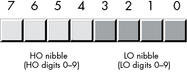
Figure 2-24: BCD data representation in memory
As you can see, BCD storage isn’t particularly memory efficient. For example, an 8-bit BCD variable can represent values in the range 0 to 99, while that same 8 bits, when holding a binary value, can represent values in the range 0 to 255. Likewise, a 16-bit binary value can represent values in the range 0 to 65,535, while a 16-bit BCD value can represent only about one-sixth of those values (0 to 9999).
However, it’s easy to convert BCD values between the internal numeric representation and their string representation, and to encode multi-digit decimal values in hardware (for example, using a thumb wheel or dial) using BCD. For these two reasons, you’re likely to see people using BCD in embedded systems (such as toaster ovens, alarm clocks, and nuclear reactors) but rarely in general-purpose computer software.
The Intel x86-64 floating-point unit supports a pair of instructions for loading and storing BCD values. Internally, however, the FPU converts these BCD values to binary and performs all calculations in binary. It uses BCD only as an external data format (external to the FPU, that is). This generally produces more-accurate results and requires far less silicon than having a separate coprocessor that supports decimal arithmetic.
2.15 Characters
Perhaps the most important data type on a personal computer is the character data type. The term character refers to a human or machine-readable symbol that is typically a non-numeric entity, specifically any symbol that you can normally type on a keyboard (including some symbols that may require multiple keypresses to produce) or display on a video display. Letters (alphabetic characters), punctuation symbols, numeric digits, spaces, tabs, carriage returns (enter), other control characters, and other special symbols are all characters.
Most computer systems use a 1- or 2-byte sequence to encode the various characters in binary form. Windows, macOS, FreeBSD, and Linux use either the ASCII or Unicode encodings for characters. This section discusses the ASCII and Unicode character sets and the character declaration facilities that MASM provides.
2.15.1 The ASCII Character Encoding
The American Standard Code for Information Interchange (ASCII) character set maps 128 textual characters to the unsigned integer values 0 to 127 (0 to 7Fh). Although the exact mapping of characters to numeric values is arbitrary and unimportant, using a standardized code for this mapping is important because when you communicate with other programs and peripheral devices, you all need to speak the same “language.” ASCII is a standardized code that nearly everyone has agreed on: if you use the ASCII code 65 to represent the character A, then you know that a peripheral device (such as a printer) will correctly interpret this value as the character A whenever you transmit data to that device.
Despite some major shortcomings, ASCII data has become the standard for data interchange across computer systems and programs.16 Most programs can accept ASCII data; likewise, most programs can produce ASCII data. Because you will be dealing with ASCII characters in assembly language, it would be wise to study the layout of the character set and memorize a few key ASCII codes (for example, for 0, A, a, and so on). See Appendix A for a list of all the ASCII character codes.
The ASCII character set is divided into four groups of 32 characters. The first 32 characters, ASCII codes 0 to 1Fh (31), form a special set of nonprinting characters, the control characters. We call them control characters because they perform various printer/display control operations rather than display symbols. Examples include carriage return, which positions the cursor to the left side of the current line of characters;17 line feed, which moves the cursor down one line on the output device; and backspace, which moves the cursor back one position to the left.
Unfortunately, different control characters perform different operations on different output devices. Little standardization exists among output devices. To find out exactly how a control character affects a particular device, you will need to consult its manual.
The second group of 32 ASCII character codes contains various punctuation symbols, special characters, and the numeric digits. The most notable characters in this group include the space character (ASCII code 20h) and the numeric digits (ASCII codes 30h to 39h).
The third group of 32 ASCII characters contains the uppercase alphabetic characters. The ASCII codes for the characters A to Z lie in the range 41h to 5Ah (65 to 90). Because there are only 26 alphabetic characters, the remaining 6 codes hold various special symbols.
The fourth, and final, group of 32 ASCII character codes represents the lowercase alphabetic symbols, 5 additional special symbols, and another control character (delete). The lowercase character symbols use the ASCII codes 61h to 7Ah. If you convert the codes for the upper- and lowercase characters to binary, you will notice that the uppercase symbols differ from their lowercase equivalents in exactly one bit position. For example, consider the character codes for E and e appearing in Figure 2-25.
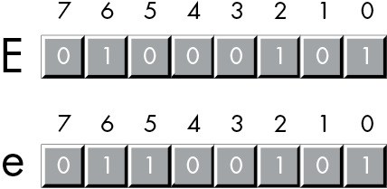
Figure 2-25: ASCII codes for E and e
The only place these two codes differ is in bit 5. Uppercase characters always contain a 0 in bit 5; lowercase alphabetic characters always contain a 1 in bit 5. You can use this fact to quickly convert between upper- and lowercase. If you have an uppercase character, you can force it to lowercase by setting bit 5 to 1. If you have a lowercase character, you can force it to uppercase by setting bit 5 to 0. You can toggle an alphabetic character between upper- and lowercase by simply inverting bit 5.
Indeed, bits 5 and 6 determine which of the four groups in the ASCII character set you’re in, as Table 2-13 shows.
Table 2-13: ASCII Groups
| Bit 6 | Bit 5 | Group |
| 0 | 0 | Control characters |
| 0 | 1 | Digits and punctuation |
| 1 | 0 | Uppercase and special |
| 1 | 1 | Lowercase and special |
So you could, for instance, convert any upper- or lowercase (or corresponding special) character to its equivalent control character by setting bits 5 and 6 to 0.
Consider, for a moment, the ASCII codes of the numeric digit characters appearing in Table 2-14.
Table 2-14: ASCII Codes for Numeric Digits
| Character | Decimal | Hexadecimal |
| 0 | 48 | 30h |
| 1 | 49 | 31h |
| 2 | 50 | 32h |
| 3 | 51 | 33h |
| 4 | 52 | 34h |
| 5 | 53 | 35h |
| 6 | 54 | 36h |
| 7 | 55 | 37h |
| 8 | 56 | 38h |
| 9 | 57 | 39h |
The LO nibble of the ASCII code is the binary equivalent of the represented number. By stripping away (that is, setting to 0) the HO nibble of a numeric character, you can convert that character code to the corresponding binary representation. Conversely, you can convert a binary value in the range 0 to 9 to its ASCII character representation by simply setting the HO nibble to 3. You can use the logical AND operation to force the HO bits to 0; likewise, you can use the logical OR operation to force the HO bits to 0011b (3).
Unfortunately, you cannot convert a string of numeric characters to their equivalent binary representation by simply stripping the HO nibble from each digit in the string. Converting 123 (31h 32h 33h) in this fashion yields 3 bytes, 010203h, but the correct value for 123 is 7Bh. The conversion described in the preceding paragraph works only for single digits.
2.15.2 MASM Support for ASCII Characters
MASM provides support for character variables and literals in your assembly language programs. Character literal constants in MASM take one of two forms: a single character surrounded by apostrophes or a single character surrounded by quotes, as follows:
'A' "A" Both forms represent the same character (A).
If you wish to represent an apostrophe or a quote within a string, use the other character as the string delimiter. For example:
'A "quotation" appears within this string'
"Can't have quotes in this string"
Unlike the C/C++ language, MASM doesn’t use different delimiters for single-character objects versus string objects, or differentiate between a character constant and a string constant with a single character. A character literal constant has a single character between the quotes (or apostrophes); a string literal has multiple characters between the delimiters.
To declare a character variable in a MASM program, you use the byte data type. For example, the following declaration demonstrates how to declare a variable named UserInput:
               .data
UserInput      byte ?
This declaration reserves 1 byte of storage that you could use to store any character value (including 8-bit extended ASCII/ANSI characters). You can also initialize character variables as follows:
              .data
TheCharA      byte 'A'
ExtendedChar  byte 128 ; Character code greater than 7Fh
Because character variables are 8-bit objects, you can manipulate them using 8-bit registers. You can move character variables into 8-bit registers, and you can store the value of an 8-bit register into a character variable.
2.16 The Unicode Character Set
The problem with ASCII is that it supports only 128 character codes. Even if you extend the definition to 8 bits (as IBM did on the original PC), you’re limited to 256 characters. This is way too small for modern multinational/multilingual applications. Back in the 1990s, several companies developed an extension to ASCII, known as Unicode, using a 2-byte character size. Therefore, (the original) Unicode supported up to 65,536 character codes.
Alas, as well-thought-out as the original Unicode standard could be, systems engineers discovered that even 65,536 symbols were insufficient. Today, Unicode defines 1,112,064 possible characters, encoded using a variable-length character format.
2.16.1 Unicode Code Points
A Unicode code point is an integer value that Unicode associates with a particular character symbol. The convention for Unicode code points is to specify the value in hexadecimal with a preceding U+ prefix; for example, U+0041 is the Unicode code point for the A character (41h is also the ASCII code for A; Unicode code points in the range U+0000 to U+007F correspond to the ASCII character set).
2.16.2 Unicode Code Planes
The Unicode standard defines code points in the range U+000000 to U+10FFFF (10FFFFh is 1,114,111, which is where most of the 1,112,064 characters in the Unicode character set come from; the remaining 2047 code points are reserved for use as surrogates, which are Unicode extensions).18 The Unicode standard breaks this range up into 17 multilingual planes, each supporting up to 65,536 code points. The HO two hexadecimal digits of the six-digit code point value specify the multilingual plane, and the remaining four digits specify the character within the plane.
The first multilingual plane, U+000000 to U+00FFFF, roughly corresponds to the original 16-bit Unicode definition; the Unicode standard calls this the Basic Multilingual Plane (BMP). Planes 1 (U+010000 to U+01FFFF), 2 (U+020000 to U+02FFFF), and 14 (U+0E0000 to U+0EFFFF) are supplementary (extension) planes. Unicode reserves planes 3 to 13 for future expansion, and planes 15 and 16 for user-defined character sets.
Obviously, representing Unicode code points outside the BMP requires more than 2 bytes. To reduce memory usage, Unicode (specifically the UTF-16 encoding; see the next section) uses 2 bytes for the Unicode code points in the BMP, and uses 4 bytes to represent code points outside the BMP. Within the BMP, Unicode reserves the surrogate code points (U+D800–U+DFFF) to specify the 16 planes after the BMP. Figure 2-26 shows the encoding.
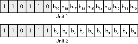
Figure 2-26: Surrogate code point encoding for Unicode planes 1 to 16
Note that the two words (unit 1 and unit 2) always appear together. The unit 1 value (with HO bits 110110b) specifies the upper 10 bits (b10 to b19) of the Unicode scalar, and the unit 2 value (with HO bits 110111b) specifies the lower 10 bits (b0 to b9) of the Unicode scalar. Therefore, bits b16 to b19 (plus one) specify Unicode plane 1 to 16. Bits b0 to b15 specify the Unicode scalar value within the plane.
2.16.3 Unicode Encodings
As of Unicode v2.0, the standard supports a 21-bit character space capable of handling over a million characters (though most of the code points remain reserved for future use). Rather than use a 3-byte (or worse, 4-byte) encoding to allow the larger character set, Unicode, Inc., allowed different encodings, each with its own advantages and disadvantages.
UTF-32 uses 32-bit integers to hold Unicode scalars.19 The advantage to this scheme is that a 32-bit integer can represent every Unicode scalar value (which requires only 21 bits). Programs that require random access to characters in strings (without having to search for surrogate pairs) and other constant-time operations are (mostly) possible when using UTF-32. The obvious drawback to UTF-32 is that each Unicode scalar value requires 4 bytes of storage (twice that of the original Unicode definition and four times that of ASCII characters).
The second encoding format the Unicode supports is UTF-16. As the name suggests, UTF-16 uses 16-bit (unsigned) integers to represent Unicode values. To handle scalar values greater than 0FFFFh, UTF-16 uses the surrogate pair scheme to represent values in the range 010000h to 10FFFFh (see the discussion of code planes and surrogate code points in the previous section). Because the vast majority of useful characters fit into 16 bits, most UTF-16 characters require only 2 bytes. For those rare cases where surrogates are necessary, UTF-16 requires two words (32 bits) to represent the character.
The last encoding, and unquestionably the most popular, is UTF-8. The UTF-8 encoding is upward compatible from the ASCII character set. In particular, all ASCII characters have a single-byte representation (their original ASCII code, where the HO bit of the byte containing the character contains a 0 bit). If the UTF-8 HO bit is 1, UTF-8 requires additional bytes (1 to 3 additional bytes) to represent the Unicode code point. Table 2-15 provides the UTF-8 encoding schema.
Table 2-15: UTF-8 Encoding
| Bytes | Bits for code point | First code point | Last code point | Byte 1 | Byte 2 | Byte 3 | Byte 4 |
| 1 | 7 | U+00 | U+7F | 0xxxxxxx | |||
| 2 | 11 | U+80 | U+7FF | 110xxxxx | 10xxxxxx | ||
| 3 | 16 | U+800 | U+FFFF | 1110xxxx | 10xxxxxx | 10xxxxxx | |
| 4 | 21 | U+10000 | U+10FFFF | 11110xxx | 10xxxxxx | 10xxxxxx | 10xxxxxx |
The xxx... bits are the Unicode code point bits. For multi-byte sequences, byte 1 contains the HO bits, byte 2 contains the next HO bits, and so on. For example, the 2-byte sequence 11011111b, 10000001b corresponds to the Unicode scalar 0000_0111_1100_0001b (U+07C1).
2.17 MASM Support for Unicode
Unfortunately, MASM provides almost zero support for Unicode text in a source file. Fortunately, MASM’s macro facilities provide a way for you to create your own Unicode support for strings in MASM. See Chapter 13 for more details on MASM macros. I will also return to this subject in The Art of 64-Bit Assembly, Volume 2, where I will spend considerable time describing how to force MASM to accept and process Unicode strings in source and resource files.
2.18 For More Information
For general information about data representation and Boolean functions, consider reading my book Write Great Code, Volume 1, Second Edition (No Starch Press, 2020), or a textbook on data structures and algorithms (available at any bookstore).
ASCII, EBCDIC, and Unicode are all international standards. You can find out more about the Extended Binary Coded Decimal Interchange Code (EBCDIC) character set families on IBM’s website (http://www.ibm.com/). ASCII and Unicode are both International Organization for Standardization (ISO) standards, and ISO provides reports for both character sets. Generally, those reports cost money, but you can also find out lots of information about the ASCII and Unicode character sets by searching for them by name on the internet. You can also read about Unicode at http://www.unicode.org/. Write Great Code also contains additional information on the history, use, and encoding of the Unicode character set.
2.19 Test Yourself
- What does the decimal value 9384.576 represent (in terms of powers of 10)?
- Convert the following binary values to decimal:
- 1010
- 1100
- 0111
- 1001
- 0011
- 1111
- Convert the following binary values to hexadecimal:
- 1010
- 1110
- 1011
- 1101
- 0010
- 1100
- 1100_1111
- 1001_1000_1101_0001
- Convert the following hexadecimal values to binary:
- 12AF
- 9BE7
- 4A
- 137F
- F00D
- BEAD
- 4938
- Convert the following hexadecimal values to decimal:
- A
- B
- F
- D
- E
- C
- How many bits are there in a
- Word
- Qword
- Oword
- Dword
- BCD digit
- Byte
- Nibble
- How many bytes are there in a
- Word
- Dword
- Qword
- Oword
- How different values can you represent with a
- Nibble
- Byte
- Word
- Bit
- How many bits does it take to represent a hexadecimal digit?
- How are the bits in a byte numbered?
- Which bit number is the LO bit of a word?
- Which bit number is the HO bit of a dword?
- Compute the logical AND of the following binary values:
- 0 and 0
- 0 and 1
- 1 and 0
- 1 and 1
- Compute the logical OR of the following binary values:
- 0 and 0
- 0 and 1
- 1 and 0
- 1 and 1
- Compute the logical XOR of the following binary values:
- 0 and 0
- 0 and 1
- 1 and 0
- 1 and 1
- The logical NOT operation is the same as XORing with what value?
- Which logical operation would you use to force bits to 0 in a bit string?
- Which logical operation would you use to force bits to 1 in a bit string?
- Which logical operation would you use to invert all the bits in a bit string?
- Which logical operation would you use to invert selected bits in a bit string?
- Which machine instruction will invert all the bits in a register?
- What is the two’s complement of the 8-bit value 5 (00000101b)?
- What is the two’s complement of the signed 8-bit value –2 (11111110)?
- Which of the following signed 8-bit values are negative?
- 1111_1111b
- 0111_0001b
- 1000_0000b
- 0000_0000b
- 1000_0001b
- 0000_0001b
- Which machine instruction takes the two’s complement of a value in a register or memory location?
- Which of the following 16-bit values can be correctly sign-contracted to 8 bits?
- 1111_1111_1111_1111
- 1000_0000_0000_0000
- 000_0000_0000_0001
- 1111_1111_1111_0000
- 1111_1111_0000_0000
- 0000_1111_0000_1111
- 0000_0000_1111_1111
- 0000_0001_0000_0000
- What machine instruction provides the equivalent of an HLL
gotostatement? - What is the syntax for a MASM statement label?
- What flags are the condition codes?
- JE is a synonym for what instruction that tests a condition code?
- JB is a synonym for what instruction that tests a condition code?
- Which conditional jump instructions transfer control based on an unsigned comparison?
- Which conditional jump instructions transfer control based on a signed comparison?
- How does the SHL instruction affect the zero flag?
- How does the SHL instruction affect the carry flag?
- How does the SHL instruction affect the overflow flag?
- How does the SHL instruction affect the sign flag?
- How does the SHR instruction affect the zero flag?
- How does the SHR instruction affect the carry flag?
- How does the SHR instruction affect the overflow flag?
- How does the SHR instruction affect the sign flag?
- How does the SAR instruction affect the zero flag?
- How does the SAR instruction affect the carry flag?
- How does the SAR instruction affect the overflow flag?
- How does the SAR instruction affect the sign flag?
- How does the RCL instruction affect the carry flag?
- How does the RCL instruction affect the zero flag?
- How does the RCR instruction affect the carry flag?
- How does the RCR instruction affect the sign flag?
- A shift left is equivalent to what arithmetic operation?
- A shift right is equivalent to what arithmetic operation?
- When performing a chain of floating-point addition, subtraction, multiplication, and division operations, which operations should you try to do first?
- How should you compare floating-point values for equality?
- What is a normalized floating-point value?
- How many bits does a (standard) ASCII character require?
- What is the hexadecimal representation of the ASCII characters 0 through 9?
- What delimiter character(s) does MASM use to define character constants?
- What are the three common encodings for Unicode characters?
- What is a Unicode code point?
- What is a Unicode code plane?