Chapter 5
Module (Unit) Testing
Up to this point we have largely ignored the mechanics of testing and the size of the program being tested. However, because large programs (say, of 500 statements or 50-plus classes) require special testing treatment, in this chapter we consider an initial step in structuring the testing of a large program: module testing. Chapters 6 and 7 enumerate the remaining steps.
Module testing (or unit testing) is a process of testing the individual subprograms, subroutines, classes, or procedures in a program. More specifically, rather than initially testing the program as a whole, testing is first focused on the smaller building blocks of the program. The motivations for doing this are threefold. First, module testing is a way of managing the combined elements of testing, since attention is focused initially on smaller units of the program. Second, module testing eases the task of debugging (the process of pinpointing and correcting a discovered error), since, when an error is found, it is known to exist in a particular module. Finally, module testing introduces parallelism into the program testing process by presenting us with the opportunity to test multiple modules simultaneously.
The purpose of module testing is to compare the function of a module to some functional or interface specification defining the module. To reemphasize the goal of all testing processes, the objective here is not to show that the module meets its specification, but that the module contradicts the specification. In this chapter, we address module testing from three points of view:
1. The manner in which test cases are designed.
2. The order in which modules should be tested and integrated.
3. Advice about performing the tests.
You need two types of information when designing test cases for a module test: a specification for the module and the module's source code. The specification typically defines the module's input and output parameters and its function.
Module testing is largely white-box oriented. One reason is that as you test larger entities, such as entire programs (which will be the case for subsequent testing processes), white-box testing becomes less feasible. A second reason is that the subsequent testing processes are oriented toward finding different types of errors (e.g., errors not necessarily associated with the program's logic, such as the program failing to meet its users' requirements). Hence, the test-case design procedure for a module test is the following:
Analyze the module's logic using one or more of the white-box methods, and then supplement these test cases by applying black-box methods to the module's specification.
The test-case design methods we will use were defined in Chapter 4; we will illustrate their use in a module test here through an example.
Assume that we wish to test a module named BONUS, and its function is to add $2,000 to the salary of all employees in the department or departments having the largest sales revenue. However, if an eligible employee's current salary is $150,000 or more, or if the employee is a manager, the salary is to be increased by only $1,000.
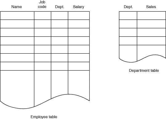
The inputs to the module are shown in the tables in Figure 5.1. If the module performs its function correctly, it returns an error code of 0. If either the employee or the department table contains no entries, it returns an error code of 1. If it finds no employees in an eligible department, it returns an error code of 2.
Figure 5.1 Input Tables to Module BONUS.
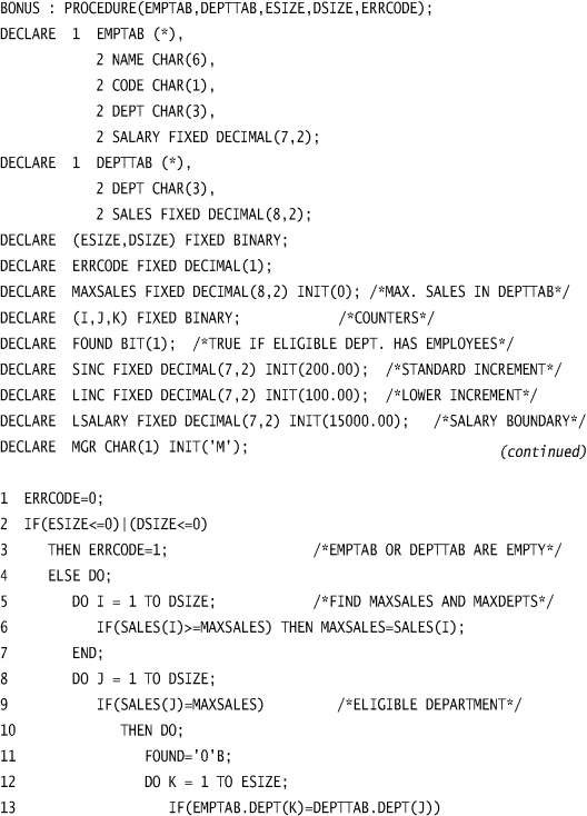
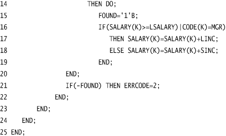
The module's source code is shown in Figure 5.2. Input parameters ESIZE and DSIZE contain the number of entries in the employee and department tables. Note that though the module is written in PL/1, the following discussion is largely language independent; the techniques are applicable to programs coded in other languages. Also, because the PL/1 logic in the module is fairly simple, virtually any reader, even those not familiar with PL/1, should be able to understand it.
Sidebar 5.1: PL/1 Background
Readers new to software development may be unfamiliar with PL/1 and think of it is a “dead” language. True, there probably is very little new development using PL/1, but maintenance of existing systems continues, and the PL/1 constructs still are a pretty good way to learn about programming procedures.
PL/1, which stands for Programming Language One, was developed in the 1960s by IBM to provide an English-like development environment for its mainframe class machines, beginning with the IBM System/360. At this time in computer history, many programmers were migrating toward specialty languages such as COBOL, designed for business application development, and Fortran, designed for scientific applications. (See Sidebar 3.1 in Chapter 3 for a little background on these languages.)
One of the main goals for PL/1 designers was a development language that could compete successfully with COBOL and Fortran while providing a development environment that would be easier to learn with a more natural language. All of the early goals for PL/1 likely never were achieved, but those early designers obviously did their homework, because PL/1 has been refined and upgraded over the years and still is in use in some environments today.
By the mid-1990s PL/1 had been extended to other computer platforms, including OS/2, Linux, UNIX, and Windows. New operating system support brought language extensions to provide more flexibility and functionality.
Regardless of which of the logic coverage techniques you use, the first step is to list the conditional decisions in the program. Candidates in this program are all IF and DO statements. By inspecting the program, we can see that all of the DO statements are simple iterations, and each iteration limit will be equal to or greater than the initial value (meaning that each loop body always will execute at least once); and the only way of exiting each loop is via the DO statement. Thus, the DO statements in this program need no special attention, since any test case that causes a DO statement to execute will eventually cause it to branch in both directions (i.e., enter the loop body and skip the loop body). Therefore, the statements that must be analyzed are:
2 IF (ESIZE<=O) | (DSIZE<=0)
6 IF (SALES(I)>= MAXSALES)
9 IF (SALES(J)= MAXSALES)
13 IF (EMPTAB.DEPT(K)= DEPTTAB.DEPT(J))
16 IF (SALARY(K)>= LSALARY) | (CODE(K)=MGR)
21 IF(-FOUND) THEN ERRCODE= 2
Given the small number of decisions, we probably should opt for multicondition coverage, but we will examine all the logic coverage criteria (except statement coverage, which always is too limited to be of use) to see their effects.
To satisfy the decision coverage criterion, we need sufficient test cases to invoke both outcomes of each of the six decisions. The required input situations to invoke all decision outcomes are listed in Table 5.1. Since two of the outcomes will always occur, there are 10 situations that need to be forced by test cases. Note that to construct Table 5.1, decision-outcome circumstances had to be traced back through the logic of the program to determine the proper corresponding input circumstances. For instance, decision 16 is not invoked by any employee meeting the conditions; the employee must be in an eligible department.
Table 5.1 Situations Corresponding to the Decision Outcomes
| Decision | True Outcome | False Outcome |
| 2 | ESIZE or DSIZE≤0 | ESIZE and DSIZE>0 |
| 6 | Will always occur at least once. | Order DEPTTAB so that a department with lower sales occurs after a department with higher sales. |
| 9 | Will always occur at least once. | All departments do not have the same sales. |
| 13 | There is an employee in an eligible department. | There is an employee who is not in an eligible department. |
| 16 | An eligible employee is either a manager or earns LSALARY or more. | An eligible employee is not a manager and earns less than LSALARY. |
| 21 | All eligible departments contain no employees. | An eligible department contains at least one employee. |
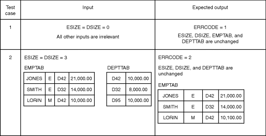
The 10 situations of interest in Table 5.1 could be invoked by the two test cases shown in Figure 5.3. Note that each test case includes a definition of the expected output, in adherence to the principles discussed in Chapter 2.
Figure 5.3 Test Cases to Satisfy the Decision-Coverage Criterion.
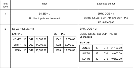
Although these two test cases meet the decision coverage criterion, it should be obvious that there could be many types of errors in the module that are not detected by these two test cases. For instance, the test cases do not explore the circumstances where the error code is 0, an employee is a manager, or the department table is empty (DSIZE<=0).
A more satisfactory test can be obtained by using the condition coverage criterion. Here we need sufficient test cases to invoke both outcomes of each condition in the decisions. The conditions and required input situations to invoke all outcomes are listed in Table 5.2. Since two of the outcomes will always occur, there are 14 situations that must be forced by test cases. Again, these situations can be invoked by only two test cases, as shown in Figure 5.4.
Table 5.2 Situations Corresponding to the Condition Outcomes
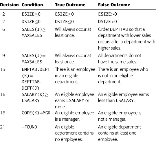
The test cases in Figure 5.4 were designed to illustrate a problem. Since they do invoke all the outcomes in Table 5.2, they satisfy the condition coverage criterion, but they are probably a poorer set of test cases than those in Figure 5.3 in terms of satisfying the decision coverage criterion. The reason is that they do not execute every statement. For example, statement 18 is never executed. Moreover, they do not accomplish much more than the test cases in Figure 5.3. They do not cause the output situation ERRORCODE=0. If statement 2 had erroneously set ESIZE=0 and DSIZE=0, this error would go undetected. Of course, an alternative set of test cases might solve these problems, but the fact remains that the two test cases in Figure 5.4 do satisfy the condition coverage criterion.
Figure 5.4 Test Cases to Satisfy the Condition Coverage Criterion.
Using the decision/condition coverage criterion would eliminate the major weakness in the test cases in Figure 5.4. Here we would provide sufficient test cases such that all outcomes of all conditions and decisions would be invoked at least once. Making Jones a manager and making Lorin a nonmanager could accomplish this. This would have the result of generating both outcomes of decision 16, thus causing us to execute statement 18.
One problem with this, however, is that it is essentially no better than the test cases in Figure 5.3. If the compiler being used stops evaluating an or expression as soon as it determines that one operand is true, this modification would result in the expression CODE(K)=MGR in statement 16 never having a true outcome. Hence, if this expression were coded incorrectly, the test cases would not detect the error.
The last criterion to explore is multicondition coverage. This criterion requires sufficient test cases such that all possible combinations of conditions in each decision are invoked at least once. This can be accomplished by working from Table 5.2. Decisions 6, 9, 13, and 21 have two combinations each; decisions 2 and 16 have four combinations each. The methodology to design the test cases is to select one that covers as many of the combinations as possible, select another that covers as many of the remaining combinations as possible, and so on. A set of test cases satisfying the multicondition coverage criterion is shown in Figure 5.5. The set is more comprehensive than the previous sets of test cases, implying that we should have selected this criterion at the beginning.
Figure 5.5 Test Cases to Catisfy the Multicondition Coverage Criterion.
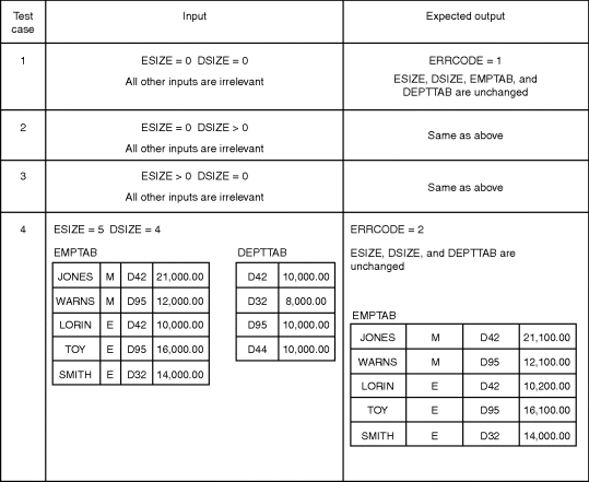
It is important to realize that module BONUS could have such a large number of errors that even the tests satisfying the multicondition coverage criterion would not detect them all. For instance, no test cases generate the situation where ERRORCODE is returned with a value of 0; thus, if statement 1 were missing, the error would go undetected. If LSALARY were erroneously initialized to $150,000.01, the mistake would go unnoticed. If statement 16 stated SALARY(K)>LSALARY instead of SALARY(K) >=LSALARY, this error would not be found. Also, whether a variety of off-by-one errors (such as not handling the last entry in DEPTTAB or EMPTAB correctly) would be detected would depend largely on chance.
Two points should be apparent now: One, the multicondition criterion is superior to the other criteria, and, two, any logic coverage criterion is not good enough to serve as the only means of deriving module tests. Hence, the next step is to supplement the tests in Figure 5.5 with a set of black-box tests. To do so, the interface specifications of BONUS are shown in the following: BONUS, a PL/1 module, receives five parameters, symbolically referred to here as EMPTAB, DEPTTAB, ESIZE, DSIZE, and ERRORCODE. The attributes of these parameters are:
DECLARE 1 EMPTAB(*), /*INPUT AND OUTPUT*/
2 NAME CHARACTER(6),
2 CODE CHARACTER(1),
2 DEPT CHARACTER(3),
2 SALARY FIXED DECIMAL(7,2);
DECLARE 1 DEPTTAB(*), /*INPUT*/
2 DEPT CHARACTER(3),
2 SALES FIXED DECIMAL(8,2);
DECLARE (ESIZE, DSIZE) FIXED BINARY; /*INPUT*/
DECLARE ERRCODE FIXED DECIMAL(1); /*OUTPUT*/
The module assumes that the transmitted arguments have these attributes. ESIZE and DSIZE indicate the number of entries in EMPTAB and DEPTTAB, respectively. No assumptions should be made about the order of entries in EMPTAB and DEPTTAB. The function of the module is to increment the salary (EMPTAB.SALARY) of those employees in the department or departments having the largest sales amount (DEPTTAB.SALES). If an eligible employee's current salary is $150,000 or more, or if the employee is a manager (EMPTAB.CODE=‘M’), the increment is $1,000; if not, the increment for the eligible employee is $2,000. The module assumes that the incremented salary will fit into field EMPTAB.SALARY. If ESIZE and DSIZE are not greater than 0, ERRCODE is set to 1 and no further action is taken. In all other cases, the function is completely performed. However, if a maximum-sales department is found to have no employee, processing continues but ERRCODE will have the value 2; otherwise, it is set to 0.
This specification is not suited to cause-effect graphing (there is not a discernible set of input conditions whose combinations should be explored); thus, boundary value analysis will be used. The input boundaries identified are as follows:
1. EMPTAB has 1 entry.
2. EMPTAB has the maximum number of entries (65,535).
3. EMPTAB has 0 entries.
4. DEPTTAB has 1 entry.
5. DEPTTAB has 65,535 entries.
6. DEPTTAB has 0 entries.
7. A maximum-sales department has 1 employee.
8. A maximum-sales department has 65,535 employees.
9. A maximum-sales department has no employees.
10. All departments in DEPTTAB have the same sales.
11. The maximum-sales department is the first entry in DEPTTAB.
12. The maximum-sales department is the last entry in DEPTTAB.
13. An eligible employee is the first entry in EMPTAB.
14. An eligible employee is the last entry in EMPTAB.
15. An eligible employee is a manager.
16. An eligible employee is not a manager.
17. An eligible employee who is not a manager has a salary of $149,999.99.
18. An eligible employee who is not a manager has a salary of $150,000.
19. An eligible employee who is not a manager has a salary of $150,000.01.
The output boundaries are as follows:
20. ERRCODE=0
21. ERRCODE=1
22. ERRCODE=2
23. The incremented salary of an eligible employee is $299,999.99.
A further test condition based on the error-guessing technique is as follows:
24. A maximum-sales department with no employees is followed in DEPTTAB with another maximum-sales department having employees.
This is used to determine whether the module erroneously terminates processing of the input when it encounters an ERRCODE=2 situation.
Reviewing these 24 conditions, numbers 2, 5, and 8 seem like impractical test cases. Since they also represent conditions that will never occur (usually a dangerous assumption to make when testing, but seemingly safe here), we exclude them. The next step is to compare the remaining 21 conditions to the current set of test cases (Figure 5.5) to determine which boundary conditions are not already covered. Doing so, we see that conditions 1, 4, 7, 10, 14, 17, 18, 19, 20, 23, and 24 require test cases beyond those in Figure 5.5.
The next step is to design additional test cases to cover the 11 boundary conditions. One approach is to merge these conditions into the existing test cases (i.e., by modifying test case 4 in Figure 5.5), but this is not recommended because doing so could inadvertently upset the complete multicondition coverage of the existing test cases. Hence, the safest approach is to add test cases to those of Figure 5.5. In doing this, the goal is to design the smallest number of test cases necessary to cover the boundary conditions. The three test cases in Figure 5.6 accomplish this. Test case 5 covers conditions 7, 10, 14, 17, 18, 19, and 20; test case 6 covers conditions 1, 4, and 23; and test case 7 covers condition 24.
Figure 5.6 Supplemental Boundary Value Analysis Test Cases for BONUS.
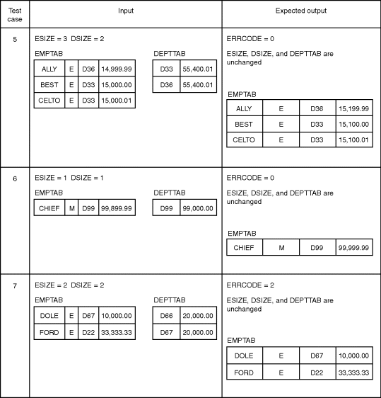
The premise here is that the logic coverage, or white-box, test cases in Figure 5.6 form a reasonable module test for procedure BONUS.
In performing the process of module testing, there are two key considerations: the design of an effective set of test cases, which was discussed in the previous section, and the manner in which the modules are combined to form a working program. The second consideration is important because it has these implications:
- The form in which module test cases are written
- The types of test tools that might be used
- The order in which modules are coded and tested
- The cost of generating test cases
- The cost of debugging (locating and repairing detected errors)
In short, then, it is a consideration of substantial importance. In this section, we discuss two approaches, incremental and nonincremental testing; in the next, we explore two incremental approaches, top-down and bottom-up development or testing.
The question pondered here is the following: Should you test a program by testing each module independently and then combining the modules to form the program, or should you combine the next module to be tested with the set of previously tested modules before it is tested? The first approach is called nonincremental, or “big-bang,” testing or integration; the second approach is known as incremental testing or integration.
The program in Figure 5.7 is used as an example. The rectangles represent the six modules (subroutines or procedures) in the program. The lines connecting the modules represent the control hierarchy of the program; that is, module A calls modules B, C, and D; module B calls module E; and so on. Nonincremental testing, the traditional approach, is performed in the following manner. First, a module test is performed on each of the six modules, testing each module as a stand-alone entity. The modules might be tested at the same time or in succession, depending on the environment (e.g., interactive versus batch-processing computing facilities) and the number of people involved. Finally, the modules are combined or integrated (e.g., “link edited”) to form the program.
Figure 5.7 Sample Six-Module Program.
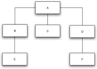
The testing of each module requires a special driver module and one or more stub modules. For instance, to test module B, test cases are first designed and then fed to module B by passing it input arguments from a driver module, a small module that must be coded to “drive,” or transmit, test cases through the module under test. (Alternatively, a test tool could be used.) The driver module must also display, to the tester, the results produced by B. In addition, since module B calls module E, something must be present to receive control when B calls E. A stub module, a special module given the name “E” that must be coded to simulate the function of module E, accomplishes this.
When the module testing of all six modules has been completed, the modules are combined to form the program.
The alternative approach is incremental testing. Rather than testing each module in isolation, the next module to be tested is first combined with the set of modules that have been tested already.
It is premature to give a procedure for incrementally testing the program in Figure 5.7, because there is a large number of possible incremental approaches. A key issue is whether we should begin at the top or bottom of the program. However, since we discuss this issue in the next section, let us assume for the moment that we are beginning from the bottom.
The first step is to test modules E, C, and F, either in parallel (by three people) or serially. Notice that we must prepare a driver for each module, but not a stub. The next step is to test B and D; but rather than testing them in isolation, they are combined with modules E and F, respectively. In other words, to test module B, a driver is written, incorporating the test cases, and the pair B-E is tested. The incremental process, adding the next module to the set or subset of previously tested modules, is continued until the last module (module A in this case) is tested. Note that this procedure could have alternatively progressed from the top to the bottom.
Several observations should be apparent at this point:
1. Nonincremental testing requires more work. For the program in Figure 5.7, five drivers and five stubs must be prepared (assuming we do not need a driver module for the top module). The bottom-up incremental test would require five drivers but no stubs. A top-down incremental test would require five stubs but no drivers. Less work is required because previously tested modules are used instead of the driver modules (if you start from the top) or stub modules (if you start from the bottom) needed in the nonincremental approach.
2. Programming errors related to mismatching interfaces or incorrect assumptions among modules will be detected earlier when incremental testing is used. The reason is that combinations of modules are tested together at an early point in time. However, when nonincremental testing is used, modules do not “see one another” until the end of the process.
3. As a result, debugging should be easier if incremental testing is used. If we assume that errors related to intermodule interfaces and assumptions do exist (a good assumption, from experience), then, if nonincremental testing has been used, the errors will not surface until the entire program has been combined. At this time, we may have difficulty pinpointing the error, since it could be anywhere within the program. Conversely, if incremental testing is used, an error of this type should be easier to pinpoint, because it is likely that the error is associated with the most recently added module.
4. Incremental testing might result in more thorough testing. If you are testing module B, either module E or A (depending on whether you started from the bottom or the top) is executed as a result. Although E or A should have been thoroughly tested previously, perhaps executing it as a result of B's module test will invoke a new condition, perhaps one that represents a deficiency in the original test of E or A. On the other hand, if nonincremental testing is used, the testing of B will affect only module B. In other words, incremental testing substitutes previously tested modules for the stubs or drivers needed in the nonincremental test. As a result, the actual modules receive more exposure by the completion of the last module test.
5. The nonincremental approach appears to use less machine time. If module A of Figure 5.7 is being tested using the bottom-up approach, modules B, C, D, E, and F probably execute during the execution of A. In a nonincremental test of A, only stubs for B, C, and E are executed. The same is true for a top-down incremental test. If module F is being tested, modules A, B, C, D, and E may be executed during the test of F ; in the nonincremental test of F, only the driver for F, plus F itself, executes. Hence, the number of machine instructions executed during a test run using the incremental approach is apparently greater than that for the nonincremental approach. Offsetting this is the fact that the nonincremental test requires more drivers and stubs than the incremental test; machine time is needed to develop the drivers and stubs.
6. At the beginning of the module testing phase, there is more opportunity for parallel activities when nonincremental testing is used (that is, all the modules can be tested simultaneously). This might be of significance in a large project (many modules and people), since the head count of a project is usually at its peak at the start of the module test phase.
In summary, observations 1 through 4 are advantages of incremental testing, while observations 5 and 6 are disadvantages. Given current trends in the computing industry (hardware costs have been decreasing, and seem destined to continue to do so, while hardware capability increases, and labor costs and the consequences of software errors are increasing), and given the fact that the earlier an error is found, the lower the cost of repairing it, you can see that observations 1 through 4 are growing in importance, whereas observation 5 is becoming less important. Observation 6 seems to be a weak disadvantage, if one at all. This leads to the conclusion that incremental testing is superior.
Top-Down versus Bottom-Up Testing
Given the conclusion of the previous section—that incremental testing is superior to nonincremental testing—we next explore two incremental strategies: top-down and bottom-up testing. Before getting into them, however, we should clarify several misconceptions. First, the terms top-down testing, top-down development, and top-down design often are used as synonyms. Top-down testing and top-down development are synonyms (they represent a strategy of ordering the coding and testing of modules), but top-down design is something quite different and independent. A program that was designed in top-down fashion can be incrementally tested in either a top-down or a bottom-up fashion.
Second, bottom-up testing (or bottom-up development) is often mistakenly equated with nonincremental testing. The reason is that bottom-up testing begins in a manner that is identical to a nonincremental test (i.e., when the bottom, or terminal, modules are tested), but as we saw in the previous section, bottom-up testing is an incremental strategy. Finally, since both strategies are incremental, we won't repeat here the advantages of incremental testing; we will discuss only the differences between top-down and bottom-up testing.
Top-Down Testing
The top-down strategy starts with the top, or initial, module in the program. After this, there is no single “right” procedure for selecting the next module to be incrementally tested; the only rule is that to be eligible to be the next module, at least one of the module's subordinate (calling) modules must have been tested previously.
Figure 5.8 is used to illustrate this strategy. A through L are the 12 modules in the program. Assume that module J contains the program's I/O read operations and module I contains the write operations.
Figure 5.8 Sample 12-Module Program.
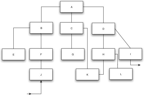
The first step is to test module A. To accomplish this, stub modules representing B, C, and D must be written. Unfortunately, the production of stub modules is often misunderstood; as evidence, you may often see such statements as “a stub module need only write a message stating ‘we got this far’ ”; and, “in many cases, the dummy module (stub) simply exits—without doing any work at all.” In most situations, these statements are false. Since module A calls module B, A is expecting B to perform some work; this work most likely is some result (output arguments) returned to A. If the stub simply returns control or writes an error message without returning a meaningful result, module A will fail, not because of an error in A, but because of a failure of the stub to simulate the corresponding module. Moreover, returning a “wired-in” output from a stub module is often insufficient. For instance, consider the task of writing a stub representing a square-root routine, a database table-search routine, an “obtain corresponding master-file record” routine, or the like. If the stub returns a fixed wired-in output, but doesn't have the particular value expected by the calling module during this invocation, the calling module may fail or produce a confusing result. Hence, the production of stubs is not a trivial task.
Another consideration is the form in which test cases are presented to the program, an important consideration that is not even mentioned in most discussions of top-down testing. In our example, the question is: How do you feed test cases to module A? The top module in typical programs neither receives input arguments nor performs input/output operations, so the answer is not immediately obvious. The answer is that the test data are fed to the module (module A in this situation) from one or more of its stubs. To illustrate, assume that the functions of B, C, and D are as follows:
B —Obtain summary of transaction file.
C —Determine whether weekly status meets quota.
D —Produce weekly summary report.
A test case for A, then, is a transaction summary returned from stub B. Stub D might contain statements to write its input data to a printer, allowing the results of each test to be examined.
In this program, another problem exists. Presumably, module A calls module B only once; therefore the problem is how to feed more than one test case to A. One solution is to develop multiple versions of stub B, each with a different wired-in set of test data to be returned to A. To execute the test cases, the program is executed multiple times, each time with a different version of stub B. Another alternative is to place test data on external files and have stub B read the test data and return them to A. In either case, keeping in mind the previous discussion, you should see that the development of stub modules is more difficult than it is often made out to be. Furthermore, it often is necessary, because of the characteristics of the program, to represent a test case across multiple stubs beneath the module under test (i.e., where the module receives data to be acted upon by calling multiple modules).
After A has been tested, an actual module replaces one of the stubs, and the stubs required by that module are added. For instance, Figure 5.9 might represent the next version of the program.
Figure 5.9 Second Step in the Top-Down Test.
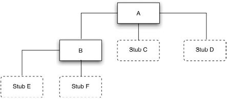
After testing the top module, numerous sequences are possible. For instance, if we are performing all the testing sequences, four examples of the many possible sequences of modules are:
1. A B C D E F G H I J K L
2. A B E F J C G K D H L I
3. A D H I K L C G B F J E
4. A B F J D I E C G K H L
If parallel testing occurs, other alternatives are possible. For instance, after module A has been tested, one programmer could take module A and test the combination A-B; another programmer could test A-C; and a third could test A-D. In general, there is no best sequence, but here are two guidelines to consider:
1. If there are critical sections of the program (perhaps module G), design the sequence such that these sections are added as early as possible. A “critical section” might be a complex module, a module with a new algorithm, or a module suspected to be error prone.
2. Design the sequence such that the I/O modules are added as early as possible.
The motivation for the first should be obvious, but the motivation for the second deserves further discussion. Recall that a problem with stubs is that some of them must contain the test cases, and others must write their input to a printer or display. However, as soon as the module accepting the program's input is added, the representation of test cases is considerably simplified; their form is identical to the input accepted by the final program (e.g., from a transaction file or a terminal). Likewise, once the module performing the program's output function is added, the placement of code in stub modules to write results of test cases might no longer be necessary. Thus, if modules J and I are the I/O modules, and if module G performs some critical function, the incremental sequence might be
A B F J D I C G E K H L
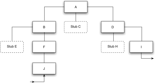
and the form of the program after the sixth increment would be that shown in Figure 5.10.
Once the intermediate state in Figure 5.10 has been reached, the representation of test cases and the inspection of results are simplified. It has another advantage, in that you have a working skeletal version of the program, that is, a version that performs actual input and output operations. However, stubs are still simulating some of the “insides.” This early skeletal version:
- Allows you to find human-factor errors and problems.
- Makes it possible to demonstrate the program to the eventual user.
- Serves as evidence that the overall design of the program is sound.
- Serves as a morale booster.
These points represent the major advantage of the top-down strategy.
On the other hand, the top-down approach has some serious shortcomings. Assume that our current state of testing is that of Figure 5.10 and that our next step is to replace stub H with module H. What we should do at this point (or earlier) is use the methods described earlier in this chapter to design a set of test cases for H. Note, however, that the test cases are in the form of actual program inputs to module J. This presents several problems. First, because of the intervening modules between J and H (F, B, A, and D), we might find it impossible to represent certain test cases to module J that test every predefined situation in H. For instance, if H is the BONUS module of Figure 5.2, it might be impossible, because of the nature of intervening module D, to create some of the seven test cases of Figures 5.5 and 5.6.
Second, because of the “distance” between H and the point at which the test data enter the program, even if it were possible to test every situation, determining which data to feed to J to test these situations in H is often a difficult mental task.
Third, because the displayed output of a test might come from a module that is a large distance away from the module being tested, correlating the displayed output to what went on in the module may be difficult or impossible. Consider adding module E to Figure 5.10. The results of each test case are determined by examining the output written by module I, but because of the intervening modules, it may be difficult to deduce the actual output of E (that is, the data returned to B).
Figure 5.10 Intermediate State in the Top-Down Test.
The top-down strategy, depending on how it is approached, may have two further problems. People occasionally feel that the strategy can be overlapped with the program's design phase. For instance, if you are in the process of designing the program in Figure 5.8, you might believe that after the first two levels are designed, modules A through D can be coded and tested while the design of the lower levels progresses. As we have emphasized elsewhere, this is usually an unwise decision. Program design is an iterative process, meaning that when we are designing the lower levels of a program's structure, we may discover desirable changes or improvements to the upper levels. If the upper levels have already been coded and tested, the desirable improvements will most likely be discarded, an unwise decision in the long run.
A final problem that often arises in practice is failing to completely test a module before proceeding to another module. This occurs for two reasons: because of the difficulty of embedding test data in stub modules, and because the upper levels of a program usually provide resources to lower levels. In Figure 5.8 we saw that testing module A might require multiple versions of the stub for module B. In practice, there is a tendency to say, “Because this represents a lot of work, I won't execute all of A's test cases now. I'll wait until I place module J in the program, at which time the representation of test cases will be easier, and remember at this point to finish testing module A.” Of course, the problem here is that we may forget to test the remainder of module A at this later point in time. Also, because upper levels often provide resources for use by lower levels (e.g., opening of files), it is difficult sometimes to determine whether the resources have been provided correctly (e.g., whether a file has been opened with the proper attributes) until the lower modules that use them are tested.
Bottom-Up Testing
The next step is to examine the bottom-up incremental testing strategy. For the most part, bottom-up testing is the opposite of top-down testing; thus, the advantages of top-down testing become the disadvantages of bottom-up testing, and the disadvantages of top-down testing become the advantages of bottom-up testing. Because of this, the discussion of bottom-up testing is shorter.
The bottom-up strategy begins with the terminal modules in the program (the modules that do not call other modules). After these modules have been tested, again there is no best procedure for selecting the next module to be incrementally tested; the only rule is that to be eligible to be the next module, all of the module's subordinate modules (the modules it calls) must have been tested previously.
Returning to Figure 5.8, the first step is to test some or all of modules E, J, G, K, L, and I, either serially or in parallel. To do so, each module needs a special driver module: a module that contains wired-in test inputs, calls the module being tested, and displays the outputs (or compares the actual outputs with the expected outputs). Unlike the situation with stubs, multiple versions of a driver are not needed, since the driver module can iteratively call the module being tested. In most cases, driver modules are easier to produce than stub modules.
As was the case earlier, a factor influencing the sequence of testing is the critical nature of the modules. If we decide that modules D and F are most critical, an intermediate state of the bottom-up incremental test might be that of Figure 5.11. The next steps might be to test E and then test B, combining B with the previously tested modules E, F, and J.
Figure 5.11 Intermediate State in the Bottom-Up Test.

A drawback of the bottom-up strategy is that there is no concept of an early skeletal program. In fact, the working program does not exist until the last module (module A) is added, and this working program is the complete program. Although the I/O functions can be tested before the whole program has been integrated (the I/O modules are being used in Figure 5.11), the advantages of the early skeletal program are not present.
The problems associated with the impossibility, or difficulty, of creating all test situations in the top-down approach do not exist here. If you think of a driver module as a test probe, the probe is being placed directly on the module being tested; there are no intervening modules to worry about. Examining other problems associated with the top-down approach, you can't make the unwise decision to overlap design and testing, since the bottom-up test cannot begin until the bottom of the program has been designed. Also, the problem of not completing the test of a module before starting another, because of the difficulty of encoding test data in versions of a stub, does not exist when using bottom-up testing.
A Comparison
It would be convenient if the top-down versus bottom-up issue were as clear-cut as the incremental versus nonincremental issue, but unfortunately it is not. Table 5.3 summarizes the relative advantages and disadvantages of the two approaches (excluding the previously discussed advantages shared by both—those of incremental testing). The first advantage of each approach might appear to be the deciding factor, but there is no evidence showing that major flaws occur more often at the top or bottom levels of the typical program. The safest way to make a decision is to weigh the factors in Table 5.3 with respect to the particular program being tested. Lacking such a program here, the serious consequences of the fourth disadvantage—of top-down testing and the availability of test tools that eliminate the need for drivers but not stubs—seems to give the bottom-up strategy the edge.
Table 5.3 Comparison of Top-Down and Bottom-Up Testing
| Top-Down Testing | |
| Advantages | Disadvantages |
| 1. Advantageous when major flaws occur toward the top of the program. | 1. Stub modules must be produced. |
| 2. Once the I/O functions are added, representation of cases is easier. | 2. Stub modules are often more complicated than they first appear to be. |
| 3. Early skeletal program allows demonstrations and boosts morale. | 3. Before the I/O functions are added, the representation of test cases in stubs can be difficult. |
| 4. Test conditions may be impossible, or very difficult, to create. | |
| 5. Observation of test output is more difficult. | |
| 6. Leads to the conclusion that design and testing can be overlapped. | |
| 7. Defers the completion of testing certain modules. | |
| Bottom-Up Testing | |
| Advantages | Disadvantages |
| 1. Advantageous when major flaws occur toward the bottom of the program. | 1. Driver modules must be produced. |
| 2. Test conditions are easier to create. | 2. The program as an entity does not exist until the last module is added. |
| 3. Observation of test results is easier. | |
Furthermore, it may be apparent that top-down and bottom-up testing are not the only possible incremental strategies.
The remaining part of the module test is the act of actually carrying out the test. A set of hints and guidelines for doing this is included here.
When a test case produces a situation where the module's actual results do not match the expected results, there are two possible explanations: either the module contains an error, or the expected results are incorrect (the test case is incorrect). To minimize this confusion, the set of test cases should be reviewed or inspected before the test is performed (that is, the test cases should be tested).
The use of automated test tools can minimize part of the drudgery of the testing process. For instance, test tools exist that eliminate the need for driver modules. Flow-analysis tools enumerate the paths through a program, find statements that can never be executed (“unreachable” code), and identify instances where a variable is used before it is assigned a value.
As was the practice earlier in this chapter, remember that a definition of the expected result is a necessary part of a test case. When executing a test, remember to look for side effects (instances where a module does something it is not supposed to do). In general, these situations are difficult to detect, but some of them may be found by checking, after execution of the test case, the inputs to the module that are not supposed to be altered. For instance, test case 7 in Figure 5.6 states that as part of the expected result, ESIZE, DSIZE, and DEPTTAB should be unchanged. When running this test case, not only should the output be examined for the correct result, but ESIZE, DSIZE, and DEPTTAB should be examined to determine whether they were erroneously altered.
The psychological problems associated with a person attempting to test his or her own programs apply as well to module testing. Rather than testing their own modules, programmers might swap them; more specifically, the programmer of the calling module is always a good candidate to test the called module. Note that this applies only to testing; the debugging of a module always should be performed by the original programmer.
Avoid throwaway test cases; represent them in such a form that they can be reused in the future. Recall the counterintuitive phenomenon in Figure 2.2. If an abnormally high number of errors is found in a subset of the modules, it is likely that these modules contain even more, as yet undetected, errors. Such modules should be subjected to further module testing, and possibly an additional code walkthrough or inspection. Finally, remember that the purpose of a module test is not to demonstrate that the module functions correctly, but to demonstrate the presence of errors in the module.
In this chapter we introduced you to some of the mechanics of testing, especially as it relates to large programs. This is a process of testing individual program components—subroutines, subprograms, classes, and procedures. In module testing you compare software functionality with the specification that defines its intended function. Module or unit testing can be an important part of a developer's toolbox to help achieve a reliable application, especially with object-oriented languages such as Java and C#. The goal in module testing is the same as for any other type of software testing: attempt to show how the program contradicts the specification. In addition to the software specification, you will need each module's source code to effect a module test.
Module testing is largely white-box testing. (See Chapter 4 for more information on white-box procedures and designing test cases for testing.) A thorough module test design will include incremental strategies such as top-down as well as bottom-up techniques.
It is helpful, when preparing for a module test, to review the psychological and economic principles laid out in Chapter 2.
One more point: Module testing software is only the beginning of an exhaustive testing procedure. You will need to move on to higher-order testing, which we address in Chapter 6, and user testing, covered in Chapter 7.

