Chapter 26
The Role of the IT Department in Managing Business Change
26.1 INTRODUCTION
The IT department frequently manages, or plays a significant role in, business change activities. These activities vary considerably in terms of the reason why the change is needed as well as the scope, complexity, timeframe and cost of the change. It is helpful to classify business change activities into the following categories, each category having very different characteristics:
- Externally imposed, mandatory changes: MiFID in 2007, Y2K in 1999 and European Monetary Union in 1998 are examples of major changes that were imposed in the investment industry by governments and regulators. The characteristics of changes of this type are that:
– The individual firm has to take part. It cannot opt out.
– There is usually a “drop-dead” date for completion of the change – e.g. 1 November 2007 for MiFID.
– The changes need to be made by a large number of industry participants at the same time. This adds to risk, because there is a danger that, for example, our firm might be ready but a major counterparty or settlement agent may not be ready.
– Within the individual firm there may be a large number of individual applications and/or business processes that require amendment or complete replacement. These types of changes rarely affect just a single application, and at the beginning of the change programme it may not be clear which applications are affected or to what extent.
– Firms often have to base the detail of the changes on interpretation of complex legal documents, whose ramifications and consequences may be the subject of debate, or even initial confusion within the industry.
- Externally driven changes: The gradual replacement of the SWIFT MT message series by the MX message series (refer to section 11.1.3) is an example of a change that all SWIFT members will need to make over a period of time if they wish to continue to use SWIFT. However, externally driven changes differ from externally imposed changes in that:
– The member firm may enjoy several years when it may use an old standard or a new one. For example, while there is a final “drop-dead” date when the MT series will be withdrawn, it will be many years after the MX messages were introduced to SWIFT members.
– Like the imposed mandatory change, it does affect large numbers of industry participants, but the lack of a single drop-dead date for all of them reduces the inherent risk. However, an element of commercial risk is introduced. For example, if our firm is a settlement agent and it is not ready with its MX messages for several months or years after its competitors, then it may lose market share.
– At the outset, it should be relatively easy to ascertain which applications will be affected, and how they will be affected.
– The detail of the changes is usually published by the instigator in comprehensive technical documents that are relatively easy to understand.
- Internally driven – business opportunities: For example, the firm wishes to trade new instruments, or new transactions in existing instruments, or otherwise add to the range of services it provides to new clients or existing clients. The characteristics of this type of change may include:
– Implementation of new applications and business processes to manage the new activities. For example, if the firm wished to trade credit default swaps for the first time then it might build or buy a new front-office system to do so, or it might decide to replace an existing front-office system that processes simpler forms of swaps but does not handle the newer types well.
– Amendments to the other applications that the front-office systems interact with, and new interfaces to those systems from the new system.
The business risks involved in this type of change include the following:
– Skills deficit: At the time that the change is instigated, the firm concerned may not yet have staff with a detailed understanding of the new services. If large numbers of firms have taken the decision to provide these new services at the same time, then staff with the right skills may be hard to recruit. Skills deficits can affect both the timeliness and the quality of the end-product.
– Commercial risk of project over-run: In business in general, the largest rewards usually go to the “early adopters”, i.e. those firms that are in a position to supply new (to the market as a whole) services first. If such a project over-runs, then the potential customer base may have already been satisfied by competitors and the firm will not benefit from the growth in market share that it expected, which was the justification for the change in the first place.
- Internally driven – process improvement: The motivation for this type of change may be any or all of the following:
– A general need to improve STP, reduce manual intervention and lower costs
– A specific need to remove an existing problem that is creating operational risk. This problem may have been noticed internally, or by external auditors and/or regulators. If the external bodies have observed the problem then the firm may be under considerable pressure to act quickly.
The scope, complexity, cost and timescales of (and therefore the operational risk inherent in) changes of this sort will vary widely. At the lower end of the scale it might involve just a small number of simple changes to a single application; but at the other end of the scale it might involve the complete replacement of, for example, the main settlement system.
If the main settlement system does need to be replaced, then there are a number of ways of achieving this objective, each of them with their own risk profile. These are the possible options that the firm could adopt (that actual options may be different at the time), sorted by risk – highest risk first:
1. Replace the single settlement system for all business activities on a single day with a number of different settlement systems for different business types.
2. Replace the single settlement system for all business activities on a single day with a new single settlement system for all business types
3. Replace the single settlement system for all business activities over a period of time with a new single settlement system for all business types
4. Replace the single settlement system for all business activities over a period of time with a number of different settlement systems for different business types.
Options 3 and 4 both involve the new system(s) coexisting with the system that they are replacing for a period of time. This may or not be practical due to external or internal constraints. While options 1 and 2 both seem to have a high level of inherent risk, there may still be good business and practical reasons for structuring the change programme in one of those ways. It is not possible to generalise further without a detailed understanding of what the firm is trying to achieve.
In order to manage change effectively, industry, commerce and government have all adopted a number of standard techniques that are described in the other sections of this chapter.
26.2 THE SOFTWARE DEVELOPMENT LIFECYCLE
The software development lifecycle (SDLC) is a standardised process of developing information systems or applications through the completion of defined steps or phases. Synonyms include systems development lifecycle, systems implementation lifecycle and software implementation lifecycle (SILC). The SLDC recognises that:
1. The further the project is from completing, the higher the risk and uncertainty. Risk and doubt decrease as the project moves closer to fulfilling the project vision.
2. Cost and resource requirements are lower at the beginning of a project, but grow as the project progresses. Once the project moves into the final closing process, cost and resource requirements again taper off dramatically. It is important for a project manager to be able to assess how much resource is actively working on their project (in terms of time or cost) so that this risk can be monitored.
3. Changes are easier and more likely at the early phases of the project lifecycle than at the completion. Changes at the beginning of the project generally cost less and have lower risk than changes at the end of the project. Therefore, stakeholders need to be happy with project deliverables from the early phases or else there is a risk that in the final phases of the project lifecycle additional costs may need to be incurred.
26.2.1 Standardised SDLC approaches
There are a number of standardised versions of the SDLC, but many organisations have adapted their own versions. In the standardised UK version, known as the Systems Life Cycle (SLC), the following names are used for each stage:
1. Terms of reference: The management decides what capabilities and objectives they wish the new system to incorporate.
2. Feasibility study: Asks whether the managements’ concept of their desired new system is actually an achievable, realistic goal – in terms of money, time and end result. Often, it may be decided to simply update an existing system, rather than to completely replace one.
3. Fact finding and recording: How is the current system used? Often questionnaires are used here, but also just monitoring (watching) the staff to see how they work is better, as people will often be reluctant to be entirely honest through embarrassment about the parts of the existing system they have trouble with and find difficult if merely asked.
4. Analysis: Free from any cost or unrealistic constraints, this stage lets minds run wild as “wonder systems” can be thought up, though all must incorporate everything asked for by the management in the Terms of reference section.
5. Design: Designers will produce one or more “models” of what they see a system eventually looking like, with ideas from the analysis section either used or discarded. A document will be produced with a description of the system, but nothing is specific: they might say “touchscreen” or “GUI operating system”, but not mention any specific brands.
6. System specification: Having generically decided on which software packages to use and hardware to incorporate, you now have to be very specific, choosing exact models, brands and suppliers for each software application and hardware device.
7. Implementation and review: Set up and install the new system (including writing any bespoke code required), train staff to use it, monitor how it operates for initial problems, and then regularly maintain thereafter. During this stage, any old system that was in use will usually be discarded once the new one has proved it is reliable and as usable.
8. Use: Obviously the system needs to be used by somebody, otherwise the above process would be completely useless.
9. Close: The last step in a system’s lifecycle is its end, which is most often forgotten when the system is designed. The system can be closed, it can be migrated to another (more modern platform) or its data can be migrated into a replacing system.
26.2.2 Customised SDLC approaches – an example
SDLCs may be customised to suit different organisations. The following is an example of a customised SDLC approach that is used by a major vendor of packaged application software to the investment industry. The company supplies large-scale systems to major industry participants, and its SDLC model reflects the large scale of most of its projects, and that it is an external vendor rather than an in-house development team. The company divides its major projects into six stages that are suitable for its business model. Each stage produces a tangible outcome. Unusually, this model combines development, testing and training into a single stage.
The six stages are shown in Table 26.1. As a guideline the company that adapted SDLC in this way expects that on a typical project the breakdowns of time spent, and the mix of technical skills and business skills will be as shown in the table.
Table 26.1 Customised SDLC stages
This SDLC defines business skills as:
Skills that relate to knowledge required to understand the business environment in which the customer functions, including experience with the application being implemented.
And it defines technical skills as:
Skills that relate to the use of the computer as a tool for solving the customer’s business problem; including knowledge of the capabilities and limitations of the hardware, operating system, database, programming languages, programming techniques and productivity aids.
This SDLC standard also includes a defined list of plans and reports that need to be produced at the end of each stage (see Table 26.2).
In detail, the six stages in this SDLC are as follows.
Table 26.2 SDLC deliverables for each stage
Stage 1 Requirements definition
Requirements definition: The main aim of this stage is to initiate the project and obtain or assure the customer’s commitment to fund the project. The tangible outcomes of this stage include the requirements definition document, which constitutes a formal agreed user request. The requirements definition document includes:
- A first cut data model of data maintained in the current system
- Identification of current problems
- Identification of project objectives – both business and technical
- Identification of project constraints
- Critical success factors
- Definition of vendor and customer responsibilities, relationships and communication channels
- Summary of investment required.
Stage 2 Analysis
The objectives of this stage are to:
- Understand the functionality of the existing system and its inherent problems and the reasons why it no longer meets the users’ needs
- Identify the essential business processes and stored data that are to be implemented in the new system
- Identify and evaluate the benefits and risks of alternative design, development, test and implementation options
- Revise the requirements definition and cost estimates if necessary.
Stage 3 Design
The objectives of this stage are to:
- Design the transactions
- Design the database
- Design the user interface
- Design the overnight processes
- Produce the test plan
- Plan for the development phase.
At the end of this stage, there should be no uncertainties about how the project will proceed.
Stage 4 Development and testing
The objectives of this stage are to:
- Produce detailed designs, write and test the programs
- Prove that the software is capable of handling both normal and peak transaction volumes and that is doesn’t interfere with other existing software. This will be achieved by integration testing and regression testing.
- Produce the user documentation
- Train the users in the new system
- Demonstrate the system’s successful operation to the customer
- Plan for Stage 5 Implementation.
Stage 5 Implementation
The main objectives of this phase are to:
- Convert data from the old system to the new system. This may involve specific tests and “dress rehearsals” of the data conversion process
- Cut over from test/training systems to the production system
- Analyse and correct any problems the users may be experiencing
- Make system operation recommendations based on performance analysis
- Ensure that user and technical documentation is complete and up to date.
Stage 6 Post-implementation
The main objectives of this stage are to:
- Fine tune system parameters in the light of experience
- Provide customer support during the critical period of the first few weeks after implementation
- Commence analysis design and development of any requirements that were deferred from the initial implementation
- Prepare the post-implementation report
- Provide customer follow-up to review the customer’s business objectives, win new business and set the baseline for future projects.
26.3 PROJECT MANAGEMENT STANDARDS
There are a number of generally accepted standards for the management and control of projects. Those that are discussed here are the standards of:
- The Project Management Institute
- PRINCE2.
Before we examine these standards in more detail, let us first of all try to define a project. Some commonly used definitions (the italics are the author’s) include the following:
1. A temporary and one-time endeavour undertaken to create a unique product or service, which brings about beneficial change or added value
2. A set of inter-related and controlled activities with start and finish dates, undertaken to achieve a unique objective conforming to specific requirements, including the restraints of time, cost and resources.
The properties of being a temporary and one-time undertaking contrast with normal operations, which are permanent repetitive functional work carried out to create the same product or service over and over again. Because the objective is to bring about change it is necessary to define the reasons for and extent of the change (the requirements); the resources that are available to make the change and the costs of those resources; and the date on which the change is required (the time constraint).
As a discipline, project management evolved from different industries such as construction, engineering and defence. Prior to the 1950s, projects were managed on an ad hoc basis using informal techniques and tools. At that time, two mathematical project scheduling models were developed; the “Program Evaluation and Review Technique” or PERT, developed by Booz-Allen & Hamilton as part of the United States Navy’s Polaris missile submarine programme; and the “Critical Path Method” (CPM), developed in a joint venture by both DuPont Corporation and Remington Rand Corporation for managing plant maintenance projects. These mathematical techniques quickly spread into many private enterprises.
Project management is the discipline of organising and managing resources (e.g. people) in such a way that the project is completed within defined scope, quality, time and cost constraints.
26.3.1 The Project Management Institute (PMI)
The Project Management Institute (PMI) was formed in 1999 in the United States to serve the interests of the project management industry. The PMI is now a global body with over 240 000 members in 160 countries. The premise of PMI is that the tools and techniques of project management are common even among the widespread application of projects from the software industry to the construction industry. In 1981, the PMI published the first edition of what is now known as A Guide to the Project Management Body of Knowledge (PMBOK Guide), containing the standards and guidelines of practice that are widely used throughout the profession.
The Guide is process based, meaning it describes work as being accomplished by processes. Processes overlap and interact throughout a project or its various phases. Processes are described in terms of:
- Inputs (documents, plans, designs, etc.)
- Tools and techniques (mechanisms applied to inputs)
- Outputs (documents, products, etc.).
The Guide recognises 44 processes that fall into five basic process groups and nine knowledge areas that are typical of almost all projects. The five process groups are:
1. Initiating
2. Planning
3. Executing
4. Controlling and monitoring
5. Closing.
The nine knowledge areas are:
1. Project integration management
2. Project scope management
3. Project time management
4. Project cost management
5. Project quality management
6. Project human resource management
7. Project communications management
8. Project risk management
9. Project procurement management.
Each of the nine knowledge areas contains the processes that need to be accomplished within its discipline in order to achieve an effective project management programme. Each of these processes also falls into one of the five basic process groups, creating a matrix structure such that every process can be related to one knowledge area and one process group.
Membership of the institute is based upon examination. The institute offers accredited education programmes based on PMBOK in partnership with academic institutions in North America, Europe and Asia, together with a large number of learning tools and publications that are available both to members and non-members.
26.3.2 PRINCE2
Projects in Controlled Environments (PRINCE) covers the management, control and organisation of a project. ‘PRINCE2’ is a registered trademark of the UKs Office of Government Commerce (OGC). PRINCE2 is derived from the earlier PRINCE technique, which was initially developed in 1989 by the Central Computer and Telecommunications Agency (CCTA) as a UK government standard for information systems (IT) project management. PRINCE soon became regularly applied outside the IT environment. PRINCE2 was released in 1996 as a generic project management method. PRINCE2 has become increasingly popular and is now the de facto standard for project management in the UK. Its use has spread beyond the UK to more than 50 other countries. The most current revision was released in 2005 by the Office of Government Commerce, and it is currently being revised for publication in 2008/9.
Project planning using PRINCE2 is product based which means the project plans are focused on delivering results and are not simply about planning when the various activities on the project will be done. PRINCE2 defines 45 separate subprocesses and organises these into eight processes as follows:
- Starting up a project (SU)
- Planning (PL)
- Initiating a project (IP)
- Directing a project (DP)
- Controlling a stage (CS)
- Managing product delivery (MP)
- Managing stage boundaries (SB)
- Closing a project (CP).
26.3.3 Starting up a project (SU)
In this process the project team is appointed and a project brief (describing, in outline, what the project is attempting to achieve and the business justification for doing it) is prepared. In addition the overall approach to be taken is decided and the next stage of the project is planned. Once this work is done, the project board is asked to authorise the next stage, that of initiating the project.
SUl: Appointing a project board and project manager
The project board is usually chaired by the project sponsor. This is normally the senior executive that instigated the change and is responsible to the business for the success of the project. The project sponsor’s role includes:
- Championing the project
- Obtaining budgets for the project
- Accepting responsibility for problems escalated from the project manager
- Signing off documents such as the business case and project initiation document.
Due to the problem solving needs of the role the project sponsor often needs to be able to exert pressure within the organisation to overcome resistance to the project. For this reason the project sponsor will ideally be a person with sufficient power and authority within the organisation. Where a project is part of a larger change programme such as MiFID, the project sponsor is often also the overall programme manager.
Other members of the project board will include executives from the various sections of the firm that will either benefit from the project or have a role in delivering it. The project manager is also a member of the project board.
The project manager is the individual responsible for delivering the project. The project manager leads and manages the project team, with the authority and responsibility to run the project on a day-to-day basis. This person’s roles may include:
- Designing and applying an appropriate project management framework for the project using relevant project standards
- Managing the production of the required deliverables
- Planning and monitoring the project
- Preparing and maintaining the project plan
- Managing project risks, including the development of contingency plans
- Liaising with programme management (if the project is part of a programme such as MiFID) and related projects to ensure that work is neither overlooked nor duplicated
- Preparing reports on overall progress and use of resources, and initiating corrective action where necessary
- Managing change control and any required configuration management
- Liaising with appointed project assurance roles to assure the overall direction and integrity of the project
- Adopting technical and quality strategy
- Identifying and obtaining any support and advice required for the management, planning and control of the project
- Managing project administration
- Conducting end project evaluation to assess how well the project was managed and preparing an end project report
- Preparing a lessons learned report
- Preparing any follow-on action recommendations as required.
In the case of small projects, the roles of project sponsor and project manager are sometimes combined, but for large projects, best practice is to separate the two roles.
SU2: Designing a project management team and SU3: Appointing a project management team
Members of the project management team report to the project manager. Typically the team will include the senior personnel responsible for various parts of the project such as design, development and testing. Team members may include representatives of the IT department, the user departments concerned and also external vendors and consultants if they are involved.
26.3.4 Planning (PL)
PRINCE2 advocates product-based planning, which means that the first task when planning is to identify and analyse products. Once the activities required to create these products are identified, then it is possible to estimate the effort required for each and schedule activities into a plan. There is always risk associated with any work and this must be analysed. Finally, this process suggests how the format of plans can be agreed and ensures that plans are completed to such a format. The planning process is divided into the following stages:
PL1 Designing a plan
PL2 Defining and analysing products
PL3 Identifying activities and dependencies
PL4 Estimating
PL5 Scheduling
PL6 Analysing risks
PL7 Completing a plan.
26.3.5 Initiating a project (IP)
This process builds on the work of the start-up (SU) activity and the project brief is augmented to form a business case – the non-technical reason for the project. The logic of the business case is that any time resources such as money or effort are consumed; they should be in support of the business.
An example could be that a software upgrade might improve system performance but the “business case” is that better performance would improve customer satisfaction. At this point the approach taken to ensure quality on the project is agreed together with the overall approach to controlling the project itself (project controls). Project files are also created as is an overall plan for the project. A plan for the next stage of the project is also created. The resultant information can be put before the project board for them to authorise the project itself. The steps in this process are:
IP1 Planning quality – quality assurance is covered in section 26.5
IP2 Planning a project
IP3 Refining the business case and risks
IP4 Setting up project controls
IP5 Setting up project files
IP6 Assembling a project initiation document (PID) – this is a logical document whose purpose is to bring together the key information needed to start the project on a sound basis, and to convey that information to all concerned with the project. The PID defines all major aspects of a project and assigns responsibilities to members of the project team. It forms the basis for the management of the project and the assessment of overall success.
26.3.6 Directing a project (DP)
These subprocesses dictate how the project board should control the overall project. As mentioned above, the project board can authorise an initiation stage and can also authorise a project. Directing a project also dictates how the project board should authorise a stage plan, including any stage plan that replaces an existing stage plan due to slippage or other unforeseen circumstances. The process also specifies the way in which the board can give ad hoc direction to a project and the way in which a project should be closed down. The individual stages within this process are:
DP1 Authorising initiation
DP2 Authorising a project
DP3 Authorising a stage or exception plan
DP4 Giving Ad hoc direction
DP5 Confirming project closure.
26.3.7 Controlling a stage (CS)
PRINCE2 suggests that projects should be broken down into stages and these subprocesses dictate how each individual stage should be controlled. Most fundamentally this includes the way in which work packages (subsets of a project that can be assigned to a specific party for execution) are authorised. It also specifies the way in which progress should be monitored and how the highlights of the progress should be reported to the project board. A means for capturing and assessing project issues is suggested together with the way in which corrective action should be taken. It also lays down under what circumstances, and by what method, project issues should be escalated to the project board.
CS1 Authorising work packages
CS2 Assessing progress
CS3 Capturing project issues
CS4 Examining project issues
CS5 Reviewing stage status
CS6 Reporting highlights
CS7 Taking corrective action
CS8 Escalating project issues
CS9 Receiving completed work package.
26.3.8 Managing product delivery (MP)
This process consists of three subprocesses and these cover the way in which a work package should be accepted, executed and delivered.
MP1 Accepting a work package
MP2 Executing a work package
MP3 Delivering a work package.
26.3.9 Managing stage boundaries (SB)
This process dictates what should be done within a stage. Managing stage boundaries (SB) dictates what should be done towards the end of a stage. The fundamental principle of this stage is to ensure that, at the end of each stage, the project stays focused on delivering business benefit. Most obviously, the next stage should be planned and the overall project plan, risk log and business case amended as necessary. The process also covers what should be done for a stage that has gone outside its tolerance levels. Finally, the process dictates how the end of the stage should be reported. There are a number of different software development methodologies that handle stage boundaries in different ways. These are examined in section 26.4.
The stages within this process are as follows:
SB1 Planning a stage
SB2 Updating a project plan
SB3 Updating a project business case
SB4 Updating the risk log
SB5 Reporting stage end
SB6 Producing an exception plan.
26.3.10 Closing a project (CP)
This process covers the things that should be done at the end of a project. The project should be formally decommissioned (and resources freed up for allocation to other activities), follow-on actions should be identified and the project itself be formally evaluated. The stages are as follows:
CP1 Decommissioning a project
CP2 Identifying follow-on actions
CP3 Project evaluation review.
26.3.11 PRINCE2 accreditation for individuals and organisations
Individuals who wish to acquire recognised project management qualifications may sit examinations to become registered PRINCE2 practitioners. Organisations that play a role in the delivery of projects may also choose to have their project management processes assessed.
Such assessment allows organisations that deliver internal projects to identity their strengths, areas for improvement and build an action plan to improve their effectiveness in the use of PRINCE2. This will lead to PRINCE2 being embedded within the organisation and facilitate delivery of the full benefits of using a structured project management method.
For those organisations that provide a project management service, in addition to the above benefits, they will also be able to provide evidence to their clients and prospective clients of their level of maturity in the use of PRINCE2.
26.4 SOFTWARE DEVELOPMENT MODELS
As part of the project planning process, organisations need to select an appropriate software development model. There are a number of commonly used software development methodologies that may be employed in a project. Most (but not all) of the differences between the models are concerned with the management of stage boundaries.
The models that are described in detail in this section are:
- Waterfall process models
- Iterative models, including:
– Prototyping
– The spiral model
– The agile model
– End-user development.
26.4.1 The waterfall model
The waterfall model (also known as Royce’s model) is a sequential model in which development is seen as flowing steadily downwards (like a waterfall) through the phases of requirements analysis, design, implementation, testing, integration and maintenance (see Figure 26.1).
Figure 26.1 Waterfall model
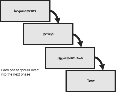
It maintains that one should move to a phase only when its preceding phase is completed and perfected. The output of each phase becomes the input of the next phase. It assumes that software development is like constructing a building – start with the foundations, then the walls, then the roof, etc. Phases of development in the waterfall model are discrete, and there is no jumping back and forth or overlap between them. However, there are various modified waterfall models that may include slight or major variations upon this process. The waterfall model with backflow (alternatively known as Royce’s final model or the implied waterfall model) recognises that issues may be discovered in one phase because of a deficiency in the previous phase, or because since the previous phase was completed there may have been external events that had not been anticipated. The solution to this problem is to go back to the previous phase and rework it before the waterfall continues (see Figure 26.2).
Figure 26.2 Waterfall model with backflow

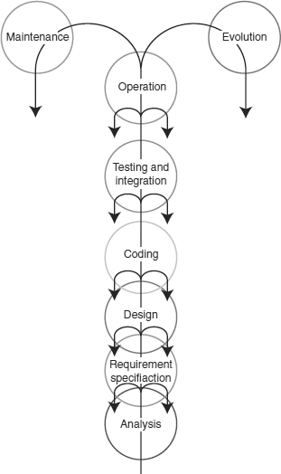
The fountain model recognises that there are opportunities for some phases of the lifecycle to occur at the same time or overlap. The overlap occurs between adjacent phases and change control processes need to be mature to ensure that work is not undertaken on incorrect assumptions (see Figure 26.3).
Figure 26.3 Fountain model
Pros and cons of the waterfall models
Advantages
1. The staged development cycle enforces discipline: every phase has a defined start and end point, and progress can be conclusively identified (through the use of milestones) by both vendor and client.
2. The emphasis on requirements and design before writing a single line of code ensures minimal wastage of time and effort and reduces the risk of schedule slippage, or of customer expectations not being met.
3. Getting the requirements and design out of the way first also improves quality; it’s much easier to catch and correct possible flaws at the design stage than at the testing stage.
4. Because the first two phases end in the production of a formal specification, the waterfall model can aid efficient knowledge transfer when team members are dispersed in different locations.
Criticisms
1. The most prominent criticism revolves around the fact that very often, customers don’t really know what they want up-front; rather, what they want emerges out of repeated two-way interactions over the course of the project. For this reason, the waterfall model, with its emphasis on up-front requirements capture and design, is seen as somewhat unrealistic and unsuitable for the complexities of the real world.
2. Given the uncertain nature of customer needs, estimating time and costs with any degree of accuracy (as the model suggests) is often extremely difficult. In general, therefore, the model is recommended for use only in projects which are relatively stable and where customer needs can be clearly identified at an early stage.
3. The model’s implicit assumption is that designs can be feasibly translated into real products; this sometimes runs into problems when developers actually begin implementation. Often, designs that look feasible on paper turn out to be expensive or difficult in practice, requiring a redesign and hence destroying the clear distinctions between phases of the traditional waterfall model.
4. Some critics also point out that the model implies a clear division of labour between, say, “designers”, “programmers” and “testers”; in reality, such a division of labour in many organisations is neither realistic nor efficient.
26.4.2 Iterative and incremental models
Several iterative/incremental models have been developed to overcome the criticisms of the waterfall model. Incremental development is a scheduling and staging strategy in which the various parts of the system are developed at different times or rates, and integrated as they are completed.
Iterative development is a rework scheduling strategy in which time is set aside to revise and improve parts of the system. A typical difference is that the output from an increment is released to users, whereas the output from an iteration is examined for further modification before release.
Common iterative/incremental models include the following:
Prototyping
Prototyping is the process of quickly putting together a working model (a prototype) in order to test various aspects of a design, illustrate ideas or features and gather early user feedback. Prototyping is often treated as an integral part of the system design process, where it is believed to reduce project risk and cost. Often one or more prototypes are made in a process of iterative and incremental development where each prototype is influenced by the performance of previous designs; in this way problems or deficiencies in design can be corrected.
When the prototype is sufficiently refined and meets the functionality, robustness, manufacturability and other design goals, the product is ready for production. The technology used to build the prototypes is not necessarily the same technology that is used to build the production system.
Advantages
- It may provide the proof of concept necessary to attract funding.
- It provides early visibility of the prototype and gives users an idea of what the final system looks like.
- It encourages active participation among users and producer.
- It is cost effective – development costs are reduced.
- It increases system development speed.
- It assists to identify any problems with the efficacy of earlier design, requirements analysis and coding activities.
- It helps to refine the potential risks associated with the delivery of the system being developed.
Criticisms
- Users, once they see the prototype, often have a hard time understanding that the finished design will not be produced for some time.
- Designers often feel compelled to use the patched-together prototype code in the real system, because they are afraid of “wasting time” starting again.
- Prototypes principally help with design decisions and user interface design – however, they cannot tell what the requirements were originally.
- Designers and end users can focus too much on user interface design and too little on producing a system that serves the business process.
26.4.3 The spiral model
This model of development combines the features of the prototyping model and the waterfall model. The spiral model is intended for large, expensive and complicated projects.
The spiral model was defined by Barry Boehm in his 1988 article “A spiral model of software development and enhancement”. This model was not the first model to discuss iterative development, but it was the first model to explain why the iteration matters. Graphically, the spiral model is represented by Figure 26.4.
Figure 26.4 Spiral model
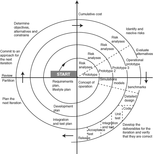
The processes in the spiral model are as follows:
1. The new system requirements are defined in as much detail as possible. This usually involves interviewing a number of users representing all the external or internal users and other aspects of the existing system.
2. A preliminary design is created for the new system.
3. A first prototype of the new system is constructed from the preliminary design. This is usually a scaled-down system, and represents an approximation of the characteristics of the final product.
4. A second prototype is evolved by a fourfold procedure:
- Evaluating the first prototype in terms of its strengths, weaknesses and risks
- Defining the requirements of the second prototype
- Planning and designing the second prototype
- Constructing and testing the second prototype.
5. At the customer’s option, the entire project can be aborted if the risk is deemed too great. Risk factors might involve development cost over-runs, operating cost miscalculation, or any other factor that could, in the customer’s judgement, result in a less-than-satisfactory final product.
6. The existing prototype is evaluated in the same manner as was the previous prototype, and, if necessary, another prototype is developed from it according to the fourfold procedure outlined above.
7. The preceding steps are iterated until the customer is satisfied that the refined prototype represents the final product desired.
8. The final system is constructed, based on the refined prototype.
9. The final system is thoroughly evaluated and tested. Routine maintenance is carried out on a continuing basis to prevent large-scale failures and to minimise downtime.