Photographic colour reproduction
INTRODUCTION
If we are to obtain the optimum record of the appearance of coloured objects, for most purposes our aim in photography must be to reproduce them as the eye sees them in daylight. Unlike the eye, however, photographic materials do not adapt themselves to changes in the light source (see chromatic adaptation of the human visual system as described in Chapters 4 and 5). They faithfully record the effects of any such changes: if a photograph is not being taken by daylight, the difference in colour quality between daylight and the source employed must be taken into account if visually optimum colour rendering is to be obtained, and it will be necessary to use colour-compensating filters. These will not necessarily be effective in extreme lighting conditions: low-pressure sodium lighting is such an example.
In practice, a technically correct rendering is rarely required in black-and-white photography, and changes in the colour quality of the illuminant can usually be ignored. In colour photography, however, very small changes in the colour quality of the illuminant may produce significant changes in the result, and accurate control of the quality of the lighting is essential if optimal results are to be obtained.
Complementary Pairs of Colours
As described in previous chapters, when any one of the three sets of colour-sensitive receptors of the eye is stimulated on its own, the eye sees blue, green or red light respectively. These three colours are known to the photographer as the primary colours, already mentioned. The sensations obtained by mixing the primaries are called secondary or complementary colours and are obtained when just two sets of receptors are stimulated. If all three sets of receptors are stimulated in equal proportions the colour perceived is neutral.
Any two coloured lights which when added together produce white are said to be of complementary colours. Thus, the secondary colours (cyan, magenta and yellow) are complementary to the primary colours (red, green and blue), as seen in Table 22.1. Some colour theorists in the field of aesthetics refer to such complementary pairs of colour as ‘harmonious colours’.
COLOUR PHOTOGRAPHIC PROCESSES
We have already seen in Chapters 1 and 5 that two techniques of colour photography have been of practical importance, namely additive and subtractive methods. Of these, additive photography was the first successful process, but we shall review it only briefly as it has been overtaken by the more successful subtractive processes. Additive systems of colour reproduction do, however, continue to be successful in the field of digital capture and display.
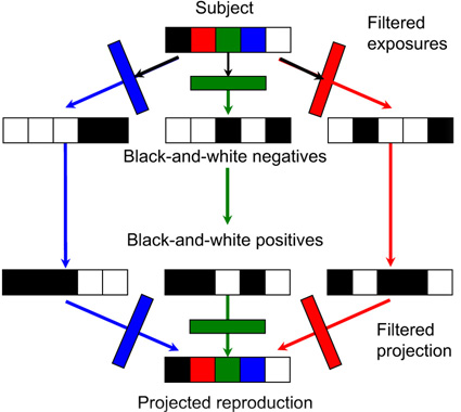
Figure 22.1 Maxwell’s additive colour photographic process.
Additive colour photography
In James Clerk Maxwell’s additive process, demonstrated in 1861 (shown diagrammatically in Figure 22.1), the selection of three spectral bands at the viewing stage was made by the original primary-colour filters used for making the negatives. The amount of each primary colour projected on the screen was controlled by the density of the silver image developed in the positive slide.
An interesting parallel between additive colour photography and digital displays is exemplified by early colour plates and, later, colour films using an integral or, sometimes, separate mosaic of red, green and blue filters, through which a panchromatic emulsion was exposed (see Figure 22.2). The exposed material was processed to yield a positive silver image. This neutral silver image effectively modulated the amount of light passing through each element of the filter mosaic, and hence controlled the image colour perceived at every point in the mosaic. Each of the filters used transmitted less than one-third of the visible spectrum and the reproductions appeared rather dark unless very powerful projectors were used.
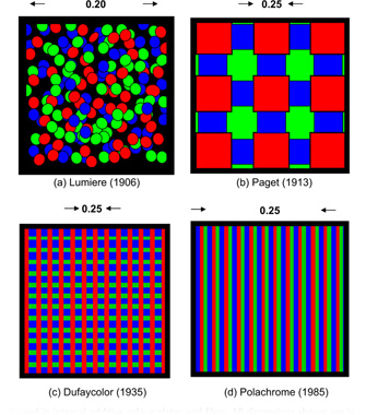
Figure 22.2 Filter mosaics used in integral additive colour plates and films. All dimensions shown are in mm.
An alternative and successful approach to the selection of spectral bands for colour reproduction is to utilize dyes of the complementary hues yellow, magenta and cyan to absorb, respectively, light of the three primary hues blue, green and red.
Subtractive processes
Subtractive systems use yellow, magenta and cyan image dyes in appropriate concentrations to control the amounts of blue, green and red light respectively transmitted or reflected by the reproduction. Thus, white is reproduced by the virtual absence of image dyes, grey by balanced moderate quantities of the three dyes, and black by a high concentration of all three dyes. Colours are reproduced by superimposed dye images of various concentrations. The effects of superimposing pairs of subtractive dyes are illustrated in Figure 22.3.
It is possible to prepare subtractive dye positives from blue, green and red separation negatives. Such dye positives can be used to superimpose the yellow, magenta and cyan images to obtain a reproduction that may be projected using one projector only, or viewed against a reflecting base. Two major processes that operated by this method were the Kodak Dye Transfer process for making reflection colour prints and the Technicolor method of preparing motion-picture release colour prints.
Integral tripacks
While subtractive images can be separately prepared and superimposed to form a colour reproduction, this method finds limited application. Most colour photographs are made using a type of material which makes blue, green and red records in discrete emulsion layers within one assembly. This specially designed emulsion assembly is called an integral tripack. Latent image records within the emulsion layers are processed in such a way that the appropriate dye images are generated in register, within the emulsion layers, by colour development. The processing chemistry is such that the blue, green and red records are made to generate complementary yellow, magenta and cyan images respectively.
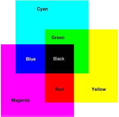
Figure 22.3 Combinations of subtractive colour image dyes on a viewing screen.
The sensitivities of the emulsions of a typical camera-speed tripack are illustrated in Figure 22.4. All three layers possess blue sensitivity. Blue light must therefore be prevented from reaching the green- and red-recording layers. This may be achieved by coating a yellow (blue-absorbing) filter layer between the uppermost blue-sensitive assembly (Figure 22.5), and the green- and red-sensitive layers below, typically resulting in the sensitivities shown in Figure 13.5.
In practice the film is more complicated and an example is shown in Figure 22.11, with the blue-recording layer on top of the other two layers, and a yellow filter layer between the blue-recording and green-recording layers. The supercoat is added to protect the emulsions from damage. The filter layer absorbs blue light sufficiently to suppress the blue sensitivities of the underlying emulsions, and an interlayer is usually positioned between the lower emulsion layers. It is common for each individual sensitivity component to be coated as two adjacent layers, one fast and one slower, the faster component being located above, nearer the camera lens, than the slower.
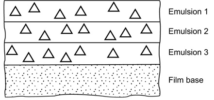
Figure 22.3 Simplified cross-section of an elementary integral tripack colour film. The symbol ∆ denotes a silver halide emulsion grain..
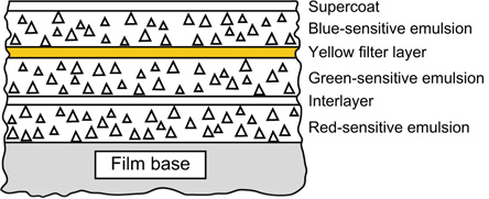
Figure 22.5 Construction of a simple integral tripack colour film.
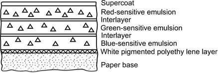
Figure 22.6 Cross-section of a tripack colour-printing paper. Compare the layer order with that in Figure 22.5. and note the absence of a yellow filter layer.
A more elegant solution to the problem of inherent blue sensitivity of the green- and red-recording layers is to suppress it within the emulsion layers themselves. This may be achieved in materials for camera use by, for example, the use of tabular emulsion crystals of very high surface-area-to-volume ratio. The blue response depends on the amount of silver halide in each crystal, a volume effect, but the dyesensitized response depends on the quantity of adsorbed dye, a surface-area effect. A high area-to-volume ratio therefore increases the sensitivity in the sensitized region compared with the inherent blue sensitivity, and with modern sensitization techniques this may be so low as to require no yellow filter layer.
In print materials it is often possible to reduce and confine the inherent sensitivity of red- and green-sensitized emulsions to the far blue and ultraviolet spectral regions, and to exclude these by a suitable filter during printing; no yellow filter layer is then required in the print material and the order of layers may be changed to suit other needs. A commonly employed order of layers in colour-printing materials is illustrated in Figure 22.6. The most important colours for the visual impression of sharpness are magenta and cyan. The red- and green-sensitive layers are therefore coated above the blue-sensitive emulsion so that the red and green optical images reach the appropriate layers without suffering prior blurring due to scatter in the blue-sensitive layer.
Formation of subtractive image dyes
Having analysed the camera image into blue, green and red components by means of the tripack film construction, it is then necessary to form the appropriate image dye in each layer. Conventionally this is achieved by the reaction of byproducts of silver development with special chemicals called colour couplers or colour formers. Developing agents of the p-phenylenediamine type yield oxidation products which will achieve this:
1. Silver halide grains which have been rendered developable by exposure to light, or otherwise, are reduced to metallic silver and the developing agent is correspondingly oxidized:
Exposed silver bromide
+ Developing agent → Metallic silver
+ Developer oxidation products + Bromide ions
2. Developer oxidation products react with chemicals called colour formers or colour couplers to form dyes. Colour developing agents of the substituted p-phenylenediamine type are used in practice, and the colour of the developed dye depends mainly on the nature of the colour former:
Developer oxidation products + Colour former →Dye
Thus, to form a dye image alongside the developed silver image a special type of developer is required and a suitable colour coupler must be provided either by coating it in the emulsion or, less commonly, by including it in the developer solution.
The dyes formed in subtractive processes would ideally possess spectral absorptions similar to those illustrated in Figure 22.7 as ‘ideal’. In practice they are not ideal and possess spectral deficiencies similar to those also shown in the figure. The consequences of these dye imperfections can be seen when the sensitometric performance of colour films is studied.
COLOUR SENSITOMETRY
Using sensitometric methods it is possible to investigate and illustrate important features of colour films in terms of both tone and colour reproduction. Tone reproduction properties are shown by neutral exposure – that is, exposure to light of the colour quality for which the film is designed, typically daylight at 5500 K or studio lighting at 3200 K. This exposure also gives information about the overall colour appearance of the photographic image. Colour exposures are used to show further colour reproduction properties not revealed by neutral exposure.
Negative–Positive colour
Colour negative films and printing papers have tone reproduction properties not unlike those of black-and-white materials, except that colour negative emulsions are designed for exposure solely on the linear portion of the characteristic curve. The materials are integral tripacks and generate a dye image of the complementary hue in each of the three emulsion layers: yellow in the blue-recording, magenta in the green-recording and cyan in the red-recording layer.
The densities of colour images are measured using a densitometer (see Chapter 8) equipped with blue, green and red filters, to give a standard set of sensitivities chosen with respect to the intended use of the images. All three colour characteristic curves are drawn on one set of axes for each individual sensitometric exposure. Typical negative characteristics obtained from a neutral exposure appear in Figure 22.8, which shows that the three curves are of similar contrast, although of slightly different speeds and different density levels. The unequal negative densities have no adverse effect on the colour balance of the final print because colour correction is carried out at the printing stage.
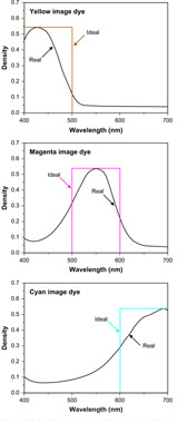
Figure 22.7 Spectral properties of ideal and real subtractive image dyes.
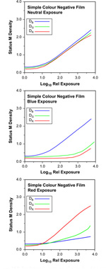
Figure 22.8 Sensitometric exposures of a simple colour negative film: neutral, blue and red.
Neutral-exposure characteristic curves are informative about the contrast and sensitometric speed of a product and the presence or absence of contrast and speed balance, but those obtained from exposures to the primary colours can also be useful. Saturated primary-colour exposures could be expected to reveal the characteristics of individual emulsion layers. The results of two such exposures of a simple colour negative film are also shown in Figure 22.8. The characteristic curves show a number of departures from the ideal in which only one colour density would change with colour exposure. Two main effects typically accompany the expected increase of one density with log exposure. The first is the low-contrast increase of an unwanted density with similar threshold to the expected curve; the second is a high-contrast increase (similar to that of the neutral curves) of an unwanted density with a threshold at a considerably higher log exposure than the primary curve shown. The former effect is due to secondary, unwanted, density of the image dye; thus, the cyan image formed on red exposure shows low-contrast blue and green secondary absorptions. The second effect is due to the exposing primary colour filter passing a significant amount of radiation to which one or both of the other two layers are sensitive. The blue exposure has clearly affected both green-and red-sensitive layers at high exposure levels. In this case of blue exposure the separation of layer responses is largely determined by the blue density of the yellow filter layer in the tripack, at exposure, as all emulsion layers of the negative are blue sensitive. The results of red exposure show a combination of the two effects, revealing secondary blue and green absorptions of the cyan dye and the overlap of the red radiation band passed by the filter with the spectral sensitivity band of the green-sensitive emulsion.
Modern colour negative films yield characteristic curves, which differ from those shown in Figure 22.8 owing to methods adopted to improve colour reproduction. The most obvious of these is colour masking, which is designed to eliminate the printing effect of unwanted dye absorptions by making them constant throughout the exposure range of the negative. Important characteristics of a masked colour negative film are shown in Figure 22.9. The obvious visual difference between masked and unmasked colour negatives is the orange appearance of the former. This appears as high blue and green densities, even at Dmin. The results of colour masking can clearly be seen in the case of the red exposure illustrated in Figure 22.9. Unwanted blue and green absorptions of the cyan image are corrected by this masking, which would ideally result in blue and green characteristic curves of zero gradient, i.e. constant blue and green densities at all red exposure levels. In this example, the green absorption is slightly under-corrected and the blue is over-corrected. The green density does rise a little with increased exposure, while the blue falls. Some degree of over-correction, or over-masking, may be deliberately introduced by manufacturers in negative products designed to give very colourful prints.
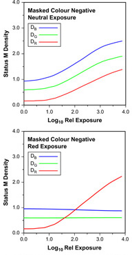
Figure 22.9 Sensitometric exposures of a masked colour negative film: neutral and red.
A second method of colour correction is to make image development in one layer inhibit development in the other emulsion layers. If an emulsion has an appreciable developed density this may be reduced by development of another layer, giving a corrective effect similar to that of colour masking. Such inter-image effects are not always simply detected by measuring integral colour densities but they are sometimes detectable. Inter-image effects, for example, would appear to be operating in the negative film illustrated in Figure 22.8. Blue exposure results in development of the yellow image in the top layer of the tripack and this, in turn, inhibits development of the green- and red-sensitive layers so that the red minimum density, in particular, falls while the blue density increases. Such unexpectedly low image densities are often the only clue to the existence of inter-image effects to be found using integral densitometry.
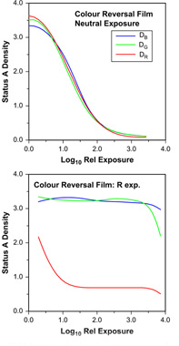
Figure 22.10 Neutral and red sensitometric exposures of colour reversal film.
Current colour negative films (see Figures 22.11 and 22.12) use both colour masking and inter-image effects, allowing excellent colour correction with relatively low mask densities. The mask density and its colour, however, remain far too great for this colour correction method to be used in materials such as reversal films, designed for viewing rather than printing. The consequences of dye deficiencies in such systems are, however, less important than in negative–positive systems, where two reproduction stages are involved, with a consequent reinforcement of colour degradation. Colour reversal films do, however, generally exhibit significant and beneficial inter-image effects.
Reversal colour
Colour reversal films are constructed similarly to integral tripack negative films, but without the colour masking components present in negative films. The positive nature of the image springs primarily from a major difference in the processing carried out, not from the emulsions used in the film. As in the negative, the dye image generated in each layer is complementary in colour to the sensitivity of the emulsion.
The results of neutral exposure are illustrated in Figure 22.10, and show typical positive characteristic curves. Unlike colour negative materials it is important that the results of a neutral exposure on reversal film should appear truly neutral: no simple correction can be carried out once the image has been developed. In the case illustrated, the curves show sufficiently similar densities for the result to be visually satisfactory. The major difference is at so high a density as to be imperceptible – there is rarely any perceived colour in regions of deep shadow.
Colour exposures show various departures from the ideal and are sometimes quite difficult to interpret. The two main effects are, however, as easily characterized as they were for colour negatives: the unexpected decrease of density with log exposure at low contrast and the decrease in a colour density other than that of the exposure at high contrast. The former effect is generally caused by the secondary absorption of an image dye, and the latter shows the overlap between the spectral region passed by the exposing filter and the sensitivity band of the emulsion concerned. Red exposure can yield characteristic curves showing the effects of both secondary absorptions and inter-image effects. The expected result of red exposure is a decrease in red density with increasing exposure. This is seen in Figure 22.10, but other results are also observed. The initial large decrease in the density of the cyan dye image with increased exposure is accompanied by a small decrease in the green density, caused by the correspondingly reduced unwanted secondary green absorption of the cyan image dye. An increase in blue density is observed over the same exposure range, and this indicates the existence of an inter-image effect in which the development of an image in the red-sensitive layer inhibits the development of an image in the blue-sensitive layer. This takes place during colour development, and represents a colour correction effect akin to masking. The apparently high minimum red density, in the case of red exposure, is due to unwanted red absorptions of the yellow and, particularly, magenta image dyes present in maximum concentration. At very high exposure levels, when the blue- and green-sensitive layers respond and the yellow and magenta dye concentrations fall, the red density is also reduced. The response of the blue- and green-sensitive layers to exposure through a red filter is due to the small but appreciable transmission of the red filter in the green and blue regions of the spectrum.
In essence, each primary-colour-exposed result for reversal films may be analysed in terms of three main regions. The first, at low exposure levels, shows one dye decreasing in concentration; its secondary densities are revealed by low-contrast decreases in the other two densities. The second region, at intermediate exposure, shows no change in any of the three curves, but the level of the lowest is well above the minimum found on neutral exposure, owing to the unwanted absorptions of the two image dyes present. This is exemplified by the red exposure, shown in Figure 22.10 at a log relative exposure of 2.0. Lastly, at high exposures, a region exists where sufficient actinic exposure – that is, exposure to which the emulsion is sensitive – of the remaining two emulsions leads to a decrease in the concentration of the corresponding image dyes. The secondary absorptions of these two dyes are shown by a low-contrast decrease in the third curve, for example the blue density at log relative exposures of 1.5 or more. For reversal film, departures from this scheme are caused by inter-image effects, which appear as unexpected increases in density with increased exposure, or by overlap of filter pass bands with sensitivity bands of the emulsions. This last departure from the ideal results in a compression of the three regions with the possible loss of the middle one and overlap of the other two. The middle region is not necessarily evident on green or blue exposure owing to the sensitivity separations of the three emulsions being only as much as is needed for adequate colour reproduction. Only the red exposure has sensitivity separation to spare. Indeed, the extensive range of exposures, over which no change is seen in the image, may be the cause of poor reproduction of form and texture of vivid red subjects. Vivid red tulips or roses, for example, may simply appear as red blobs with no visible tonal quality or texture.
COLOUR PHOTOGRAPHIC MATERIALS
The dye-forming development reaction allows us to generate dyes of the required colours, yellow, magenta and cyan, to control blue, green and red light respectively. To take advantage of colour development it has been necessary to make special photographic materials of the integral tripack variety described. This means that light-sensitive emulsions are coated in three layers on a suitable support, the basic construction shown in Figure 22.4. The records of blue, green and red light are made independently in the three emulsion layers. The resulting layer sensitivities are illustrated in Figure 13.6. The demand for high film speeds and improved quality has led to important developments in the technology of colour film assembly. Some of these changes are revealed by obvious but microscopic structural changes, and one such departure from the conventional tripack is shown in Figure 22.11. In order to obtain the required exposure latitude, it is customary to include two separate emulsions, a fast and a slow component of similar spectral sensitization, in each layer of a tripack colour film. This arrangement gives the highest sensitivity when the fast component is coated above the slow in each double-layer and therefore has the greatest possible access to the incoming radiation. Each sensitive layer of the elementary tripack construction is then coated as a double layer. This is preferable to blending fast and slow emulsions in a single layer, which reduces the overall speed by the absorption of light by smaller grains overlying the large at exposure. In addition, the colour-former-to-silver ratio in each component may be manipulated independently to optimize sensitometric and micro-image properties.
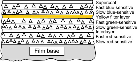
Figure 22.11 Cross-section of a modern colour negative film. Note the double-coated emulsion layers with fast components coated above the slow.
A further improvement in film speed has accompanied the structural change illustrated in Figure 22.12. In this cross-sectional diagram it will be seen that the logic, which positions the fast component above the slow in the emulsion double layers in Figure 22.11, has been extended. In this example the fast green- and red-sensitive components are adjacent and both lie above the two slow components, resulting in a partial inversion of layer order, with the fast red-sensitive layer above the slow green-sensitive layer. This structure is considerably more complex than that shown in Figure 22.11, but has been used to meet very stringent targets for speed and quality. The adoption of tabular-grain emulsions in the green- and red-sensitive layers of some products has made possible the omission of the customary yellow filter layer from the structure shown in Figure 22.11. This change, in itself, tends to reduce both the overall thickness of the coating and the scattering of input light, thus improving image sharpness.
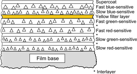
Figure 22.12 Cross-section of a modern high-speed colour negative film.
We have examined the methods used to obtain separate blue, green and red latent image records in an integral tripack. Now we shall consider how the colour developer oxidation products evolved in an emulsion layer are arranged to react with a colour former to yield the appropriate image dye. As the colour-developing agents are mobile in solution and diffuse rapidly through the swollen emulsion, we shall be concerned especially with the location of colour formers in chromogenic, or colour-forming, development.
Location of colour formers
It is required that the records of blue, green and red light shall be composed of yellow, magenta and cyan dyes respectively. This distribution of dyes is achieved by presenting colour formers to developer oxidation products in a selective manner, e.g. the oxidation products of development in the blue-recording emulsion are allowed to react only with a yellow-forming coupler. This coupler may be in solution in the colour developer, or it may be introduced into the emulsion during manufacture of the film.
Developer-soluble couplers can only be used when a single dye is to be formed in a colour development stage. Three colour developers are needed for a tripack and only one emulsion must be rendered developable before each colour development, if separation of the colour records is to be achieved. These conditions can be satisfied only in certain reversal processes of the Kodachrome type.
Couplers incorporated in the emulsions are used to form all image dyes in one colour development step. In this case only the appropriate dye-forming couplers may be permitted in an emulsion layer, if separation of the colour records is to be adequate. The colour formers therefore have to be immobilized to prevent diffusion of the couplers from layer to layer during manufacture, or later, and specially formulated interlayers are incorporated to prevent migration of oxidized colour-developing agent from layer to layer.
Two main methods of immobilizing couplers have been used. The method originally adopted by Agfa is to link the otherwise mobile coupler to a long, chemically inert chain. This chain interacts with gelatin in such a way that the molecule is effectively anchored in the layer. Such a coupler is described as being substantive to gelatin. Processes employing this type of immobilized coupler are often referred to as substantive processes. Those employing developer-soluble couplers are termed non-substantive processes.
A second immobilizing method is due to Eastman Kodak and employs shorter chemically inert chains linked to the otherwise mobile coupler. The inert chains are selected for oil solubility and render the entire molecule soluble only in oily solvents. A solution of such a coupler is made in an oily solvent and that solution dispersed as minute droplets in the emulsion, before coating. The coupler is very insoluble in water and the oily droplets are immobile in gelatin, so that the coupler is unable to diffuse out of the emulsion layer in which it is coated. Processes of the oil-dispersed coupler type are also sometimes loosely called ‘substantive processes’, although the couplers are not themselves anchored to the gelatin. The blanket term coupler incorporated may be applied to both substantive and oil-dispersed systems.
COLOUR PROCESSING
We have already encountered a number of chemical steps which are used in colour processing. Before examining the applications of such steps, we will summarize the functions of processing solutions commonly encountered in colour processes (Table 22.2).
The major differences between the processing of conventional black-and-white and of colour tripack films arise because of the need in the latter case to generate precisely the required amounts of the image dyes in all three layers (Figure 22.13). If this is not achieved, objectionable colour effects can occur: they may be largely independent of density level, resulting in a uniform colour cast over most of the tone scale, or density dependent, showing a change in colour balance with density level. The former case corresponds to a speed imbalance of the three layers while the latter corresponds to a contrast mismatch, both cases also being illustrated in Figure 22.13.
Table 22.2 The primary functions of solutions commonly used in colour processes
SOLUTION |
FUNCTION |
Black-and-white developer |
Develops a metallic silver image |
Pre-bleach |
Hardens the gelatin before entering the bleach |
Bleach |
Bleaches the silver image, usually by oxidation and rehalogenation to silver halide |
Bleach-fix |
Bleaches the silver image and fixes the silver salts formed. Leaves only the dye image required |
Colour developer |
Develops dye images together with metallic silver |
Fix |
Dissolves silver halide present after development and/or bleaching |
Fogging bath |
Replaces fogging exposure in modern reversal processes |
Hardener |
Hardens gelatin to resist damage in later processing stages |
Stabilizer |
Improves the stability of dye images, may also contain wetting agent and hardener |
Stop-fix |

Figure 22.13 Characteristic curves of colour reversal films: within specification, with poor speed balance and with poor contrast balance.
The processing conditions under which a colour film will give correct values of speed and contrast for all the emulsion layers are very limited and are generally specified closely by the film manufacturer. The specifications usually include processing times and temperatures, as well as the method and timing of agitation in processing solutions. In addition, such factors as rate of flow of wash water may also be specified. It is important to realize that any departure from the exact processing specifications laid down by the film manufacturer is likely to lead to a lower-quality result. Where manufacturers suggest process variations in order to modify a property (speed, for instance), there is often a penalty in terms of some other property such as graininess or colour reproduction. We will now consider how solutions of the types shown in Table 22.2 are used in colour processes, starting with colour reversal processing.
Reversal process
Non-substantive
As already described, there are two main types of chromogenic colour reversal process, the developer–soluble coupler type and the type with couplers incorporated in the emulsions. The Kodachrome process is of the former (non-substantive) type, the couplers being present in the three separate colour developer solutions. This process is handled in very large laboratories (of which only one remains, in North America, at the time of writing), cannot be undertaken anywhere else, and lies outside the scope of this text. It has a following among photographers, to whom it yields a very high image quality.
Coupler-incorporated films
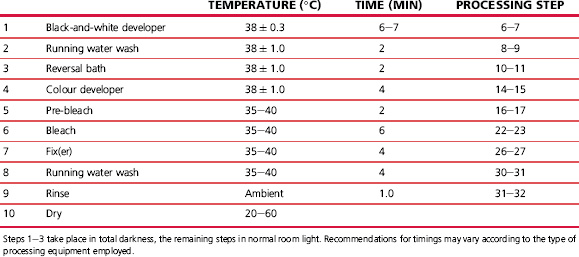
Reversal films incorporating couplers in the emulsion are simpler to process, and this may be carried out by the user, although the complexity is such that laboratory processing is more common. Such a reversal process is shown in Table 22.3, and commences with black-and-white development. After the first development the film is fogged with white light before colour development, or chemically before (or in) the colour developer. The fogged silver halide grains are colour-developed to yield positive dye images, together with metallic silver. The appropriate dye colours are ensured by the location of the yellow-forming coupler only within the blue-recording layer, the magenta-forming coupler only within the green-recording layer, and the cyan-forming coupler only within the red-recording layer. Bleaching and fixing are then carried out in order to leave only the image dyes in the gelatin layers.
An advantage of the substantive reversal process lies in the ability to modify it to change the effective emulsion speed, usually with some loss of image quality. It is possible to make a limited correction for non-standard exposure by adjusting the first development time. Manufacturers usually publish such information in their data sheets or processing guides. Modifications to effective speed of more than one stop may visibly reduce image quality. Such manipulations of first development usually do involve the sacrifice of some quality and should be used only as an emergency measure, unless the known sacrifice is tolerable.
Negative–Positive process
The negative–positive process is analogous to the conventional black-and-white process in that a negative record is made by camera exposure followed by processing. This record is not generally intended for viewing but is used to produce a usable positive by contact or projection printing on a colour print material. Since information about the blue, green and red light content of the camera image is to be available at the printing stage the blue-, green- and red-sensitive layers of the colour negative film generate yellow, magenta and cyan image dyes respectively. Metallic silver is, of course, generated at the same time, and is removed by subsequent bleaching and fixing operations. The remaining dye images form the colour negative record, the colours formed being complementary to those of the subject. The production of a colour negative record is illustrated in Figure 22.14. If integral masking is employed in the colour negative, then low-contrast positive masks are formed in the negative film at the development stage, if coloured couplers are used.
The colour negative is then the subject of the printing stage. In principle, the negative is printed on to a second integral tripack which is processed in similar fashion to a colour negative. The production of a positive print is also shown, in Figure 22.14, as the preparation of a reproduction of the subject. Certain differences of construction are shown in the positive.
Printing papers employ red- and green-sensitive emulsions whose natural blue sensitivity is very low and largely confined to wavelengths shorter than about 420 nm, a region normally filtered out in colour printing. Consequently no yellow filter layer is usually required to suppress unwanted blue sensitivity and the layer order can be selected on the basis of other criteria. It is found to be advantageous to form the image that is the most critical in determining print sharpness in the topmost layer. In most cases the cyan and magenta images are crucial for sharpness and the red-sensitive emulsion is coated uppermost, so that the red image is least affected by emulsion turbidity at exposure.
Colour print materials have characteristic curves similar to those of black-and-white print materials, as the tone reproduction requirements are quite similar. Thus, the colour negative film may have characteristic curves similar to those shown in Figure 22.15. Curves for a typical printing paper and a motion-picture release positive film are also shown. The negative illustrated is masked giving an overall colour cast, and this results in vertical displacements of the blue and green density curves, compared with the red curve. Colour masks rarely possess significant red absorption.

Figure 22.14 The negative–positive colour process.
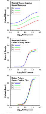
Figure 22.15 Neutral characteristics of negative–positive colour materials.
The higher blue and green densities of colour negatives are compensated for by manufacturing colour print materials with blue and green sensitivities correspondingly higher than the red sensitivity. The printing operation allows manipulation of the overall colour of the reproduction by modification of the quantities of blue, green and red light allowed to reach the print material from the negative. This may be achieved by separate additive exposures through blue, green and red filters (tricolour printing) or by making a single exposure through appropriate dilute subtractive filters, yellow, magenta or cyan (white-light printing). Thus, as control of colour balance is easy to achieve, it is not so important in negative and print materials to possess standard speed balances as it is in reversal materials. Little or no colour correction of a reversal transparency is usually possible after the taking stage, whereas in the negative–positive process, adjustment of colour balance at the printing stage is a common procedure. Modern materials are, however, so consistent that only minor printing adjustments are usually necessary to accommodate, for example, batch changes of photographic products.
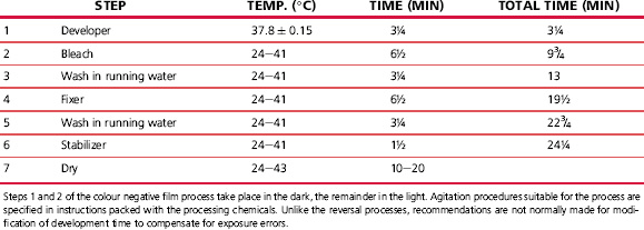
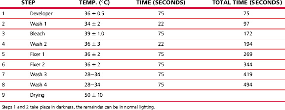
Colour paper processes normally require only two or three solutions together with the necessary washes. The process is quick and simple, using a bleachefix, or blix, solution and operating at a comparatively high temperature. Typical colour negative and colour paper processes are shown in Tables 22.4 and 22.5.
Prints from transparencies
The processes considered so far have relied on the formation of image dyes by colour development within the emulsions. There are, however, alternative approaches: one of these is to destroy dyes introduced into the emulsions at manufacture. In such processes the red exposure is arranged to lead to the destruction of a cyan dye, the green exposure leads to the destruction of a magenta dye, and blue exposure leads to the destruction of a yellow dye. Such photographic processes possess too low a sensitivity for other than specialized applications. They are, however, suitable for the production of colour prints from colour slides.
Commercial processes of this type have used the silver photographic image to bring about the chemical decomposition of dyes already coated in the emulsion layers. A current process that uses this mechanism is Ilfochrome, a process for the production of positive prints from positive transparencies. In systems of this type, the print material is an integral tripack: the uppermost, blue-sensitive emulsion contains a yellow dye, the green-sensitive layer contains a magenta dye, and the red-sensitive layer contains a cyan dye. The basic construction is shown in Figure 22.16. Because the dyes present in the emulsions have high optical densities, together with emulsion desensitization by some of the dyes, it is necessary to use high-speed emulsions in order to achieve acceptably short printing exposures.
The processing of one modern silver–dye–bleach material follows the scheme shown in Table 22.6, illustrated diagrammatically in Figure 22.17. The initial step is black-and-white development of silver halide crystals rendered developable by the printing exposure. The silver image is then used, in a bleaching stage, to reduce the dyes present in the emulsions.
This reaction may be summarized:
Dye + Acid + Metallic silver/Reduced dye fragments + Silver salts
It is arranged that the fragments resulting from the reduction of the dyes are colourless and/or soluble. Thus, in the silver–dye–bleach bath we have an image-wise reduction of the dyes by metallic silver, and corresponding oxidation of the silver. The reaction is extremely slow (owing mostly to the immobility of the reacting species), and a catalyst is necessary to obtain a satisfactory rate of bleaching. The catalyst has usually been incorporated in the silver–dye–bleach. It may, however, be carried over from solution in the black-and-white developer, within the emulsion layers.
Following the silver–dye–bleach, unwanted silver salts are removed in a fixing bath. In the process listed in Table 22.6 two fixing baths appear and there are two cascade washes which follow the fixing stage. The final result is the positive dye record retained within the gelatin, as shown in Figure 22.17.
Major advantages claimed for the silver–dye–bleach process follow from the freedom to use compounds classed as azo dyes. These possess better spectral properties than the dyes formed by chromogenic development, are markedly less fugitive to light and largely stable when stored in the dark. The better spectral properties improve the saturation and lightness of image colours, while the improved light-fastness gives a much greater life for displayed prints and the dark stability gives excellent archival properties. A further advantage is that the presence of the image dyes at exposure results in a decreased path length of light scattered within the emulsions. This improves the sharpness of the image to such an extent that it is higher than for any comparable chromogenic reflection print material. The sharpness is also improved by the use of low silver halide coating weights, made possible by the very high spectral absorptions of the azo dyes. Very little dye is therefore present to be bleached, and thus very little developed silver is required.
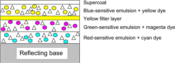
Figure 22.16 Cross-section of an elementary silver–dye–bleach material.
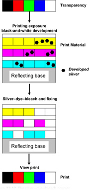
Figure 22.17 The silver–dye–bleach process.
The basic structure, shown in Figure 22.16, for silver–dye–bleach materials has been improved over time. Each emulsion layer may now be a double-coated assembly comprising a fast component containing little or no image dye and a slow component which contains all the necessary image dye complementary in hue to the sensitivity of the layer. There is no need for an interlayer between the two component emulsion layers, as the silver image in the fast emulsion is required to bleach the dye in the adjacent slow emulsion. This structure has been found to lead to a number of advantages in terms of emulsion speed, lower contrast and improved image sharpness.
In addition, silver–dye–bleach materials have been colour masked in various ways. Clearly, silver–dye–bleach print materials, whether viewed by transmission or reflection, cannot be masked in a similar way to colour negatives: whites have to be as light and neutral as possible. On the other hand, some form of inter-image effect can be used without adding to the minimum density and this, in essence, is what has been done in silver–dye–bleach materials.
In one such masking system the filter layer contains colloidal silver, i.e. very finely divided silver particles which are yellow in hue, and is an active player in promoting a favourable inter-image effect. The material is so formulated that, in correct processing conditions, physical development takes place in the filter layer, due to the presence of the colloidal silver, but not in the vicinity of images developed in the green- or red-sensitive emulsions. The physically developed silver is bleached by the silvere dyeebleach and this gives rise to bleaching of the adjacent yellow image dye in the blue-sensitive layer. Hence, wherever there is a significant amount of magenta or cyan dye in the image, there will be a corresponding reduction in the amount of yellow dye present. The yellow dye image will be at a maximum where there is no magenta or cyan present. The similarity between this and the colour masking of a negative film gives rise to ‘masking’ being used to describe the mechanism. A substantial degree of colour correction can be achieved, but without an increase in minimum density.
ENHANCEMENT OF COLOUR REPRODUCTION
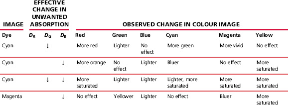
Two methods of compensating for unwanted spectral absorptions of developed image dyes have been mentioned in this chapter: colour masking in negative–positive systems and the use of inter-image effects. The latter are employed in both negative-working systems and, because no coloured mask is involved, in reversal colour films and print materials. The advantages that accrue from the use of these methods are summarized in Table 22.7, as applied to the final image in a grey-balanced system (giving a neutral reproduction of a greyscale, at all density levels, by having identical contrasts in all three colour records and ensuring correct colour balance with the exposing illuminant).
COLORIMETRY OF PHOTOGRAPHIC IMAGES
The images formed using dye-forming or, indeed, dye destruction colour photographic systems may usefully be examined using colorimetric as well as sensitometric methods. By plotting the chromaticity coordinates of image dyes at a range of densities, from Dmin to Dmax, the range of available colours can be illustrated in a chromaticity diagram (see Chapter 5). The envelope of this range of colours is called the colour gamut of the process examined and is illustrated, for a reversal colour film, in Figure 22.18.
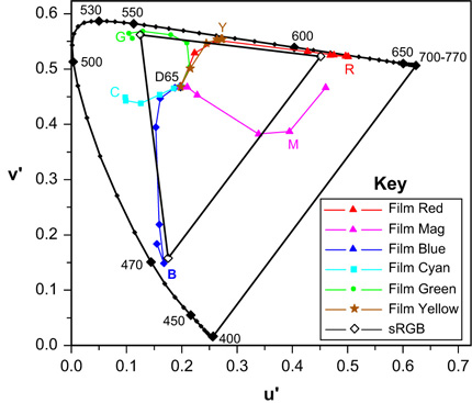
Figure 22.18 Film and monitor colour gamuts compared.
The measured samples were prepared by colour sensitometry and extend over a wide exposure range from under- to overexposure.
It will be seen that the images vary considerably over the exposure series examined in Figure 22.18. At zero density the reproductions lie close to the white point, D65, when viewed with that illuminant. As image densities increase, the purity of the record also increases – in some cases approaching 100% at the spectral locus. Yellow and red reproductions are good examples. With overexposed red subjects (see Figure 22.10) the recording is clearly quite yellow, and runs through orange to red at lesser exposures. Some variation of hue with image density can be seen for each reproduced colour.
Also shown in the figure are the colour emissions of displays operating according to sRGB specifications (see Chapter 23). The sRGB gamut is represented by the triangle linking phosphors positions in the CIE u′, v′ chromaticity diagram. If single red, green or blue pixel values lie between 1 and 255, the lightness alone changes and the chromaticity coordinates remain constant at the points shown. The addition of equal amounts of the other two primaries results in linear loci, from the points shown, to the white point of the sRGB reference display, at which all three pixel values lie at, or close to, 255. The subtractive hues, cyan, magenta and yellow, are synthesized on the monitor by combining pairs of the additive primary emissions: blue + green yielding cyan, green + red giving yellow, and red + blue forming magenta. It will be observed that, perhaps surprisingly, the dye image gamut is bigger than that of the reference sRGB display. In perceptual terms, however, this seeming advantage is, at least to some extent, counterbalanced by maximum purity reproductions on monitors being relatively lighter than those of reversal film. This extra lightness advantage may give the appearance of greater saturation.
On the other hand, the sRGB reference viewing conditions include illumination of the monitor by ambient lighting, which inevitably involves some loss of colour saturation. Reversal film transparencies and motion-picture release prints of high density scales are customarily projected in conditions of very low ambient illumination, and hence substantially preserve the colour saturation, although the dark surround lowers the perceived contrast (see Chapter 21). Thus, reversal film, in correct viewing conditions, is capable of yielding the greater colour gamut. Even at the optimum, approximately 30% of the CIE u′, v′ diagram cannot be accurately reproduced. It is, however, true that most commonly encountered colours lie within the gamuts of both systems and are acceptably reproduced – a major technological triumph in each case.
BIBLIOGRAPHY
Eggleston, J., 1984. Sensitometry for Photographers. Focal Press, London, UK.
Evans, R.M., Hanson, W.T., Brewer, W.L., 1953. Principles of Colour Photography. Wiley, New York, USA.
Hunt, R.W.G., 2001. The Reproduction of Colour, sixth ed. Wiley, New York, USA.
Langford, M., Bilissi, E., 2008. Langford’s Advanced Photography, seventh ed. Focal Press, Oxford, UK.
Proudfoot, C.N., 1997. Handbook of Photographic Science and Engineering, second ed. IS&T, Springfield, VA, USA.
Walls, H.J., Attridge, G.G., 1977. Basic Photo Science. Focal Press, London, UK.


