
Chapter 6. Shaders and Pipelines
What You’ll Learn in This Chapter
• What a shader is and how it’s used
• The basics of SPIR-V, the Vulkan shading language
• How to construct a shader pipeline and use it to do work
Shaders are small programs that are executed directly on the device. These are the fundamental building blocks of any complex Vulkan program. Shaders are perhaps more important to the operation of your program than the Vulkan API itself. This chapter introduces shaders and shader modules, shows how they are constructed from SPIR-V binaries, and illustrates how those binaries are generated from GLSL using standard tools. It discusses the construction of pipelines containing those shaders and other information required to run them, and then shows how to execute the shaders to do work on the device.
Shaders are the fundamental building blocks of work to be executed on the device. Vulkan shaders are represented by SPIR-V, which is a binary intermediate representation of program code. SPIR-V can be generated offline using a compiler, online directly inside your application, or by passing a high-level language to a library at runtime. The sample applications accompanying this book take the first approach: compiling the shaders offline and then loading the resulting SPIR-V binaries from disk.
The original shaders are written in GLSL using the Vulkan profile. This is a modified and enhanced version of the same shading language used with OpenGL. Most of the examples, therefore, discuss Vulkan features in terms of their representation in GLSL. However, it should be clear that Vulkan itself knows nothing of GLSL and doesn’t care where SPIR-V shaders come from.
An Overview of GLSL
Although not officially part of the Vulkan specification, Vulkan shares much of its heritage with OpenGL. In OpenGL, the officially supported high-level language is GLSL—the OpenGL Shading Language. Therefore, during the design of SPIR-V, much attention was paid to ensuring that at least one high-level language would be suitable for use in the generation of SPIR-V shaders. Minor modifications were made to the GLSL specification for use with Vulkan. Some features were added to enable GLSL shaders to interact cleanly with the Vulkan system, and legacy features in OpenGL that were not carried forward into Vulkan were removed from the Vulkan profile of GLSL.
The result is a slimline version of GLSL that supports most of the features of Vulkan while enabling a high level of portability between OpenGL and Vulkan. In short, if you stick to the modern features of OpenGL in an OpenGL application, much of what you write in your shaders will compile directly into SPIR-V using the official reference compiler. Of course, you are free to write your own compilers and tools or to use a third-party compiler to produce SPIR-V modules from any language you choose.
The modifications to GLSL to allow it to be used to produce a SPIR-V shader suitable for use with Vulkan are documented in the GL_KHR_vulkan_glsl extension.
In this section, we provide a brief overview of GLSL. It is assumed that the reader is somewhat familiar with high-level shading languages in general and is capable of researching GLSL in more depth if needed.
Listing 6.1 shows the simplest possible GLSL shader. It is simply an empty function, returning void, that does absolutely nothing. It’s actually a valid shader for any stage in the Vulkan pipeline, although executing it in some stages would result in some undefined behavior.
Listing 6.1: Simplest Possible GLSL Shader
#version 450 core
void main (void)
{
// Do nothing!
}
All GLSL shaders should begin with a #version directive to inform the GLSL compiler which version of GLSL we’re using. This allows the compiler to perform appropriate error checks and to allow certain language constructs that have been introduced over time.
When compiled to SPIR-V for use in Vulkan, a compiler should automatically define VULKAN to the version of the GL_KHR_vulkan_glsl extension in use such that you can wrap Vulkan-specific constructs or functionality in your GLSL shader in #ifdef VULKAN or #if VULKAN > {version} blocks in order to allow the same shaders to be used with OpenGL or Vulkan. Throughout this book, when Vulkan-specific features are discussed in the context of GLSL, it is assumed that the code beging written is either exclusively for Vulkan or is wrapped in the appropriate #ifdef preprocessor conditionals to allow it to be compiled for Vulkan.
GLSL is a C-like language, with its syntax and many of its semantics taken from C or C++. If you are a C programmer, you should be comfortable with constructs such as for and while loops; flow-control keywords such as break and continue; switch statements; relational operators such as ==, <, and >; the ternary operator a ? b : c; and so on. All of these are available in GLSL shaders.
The fundamental data types in GLSL are signed and unsigned integer and floating-point values, denoted as int, uint, and float, respectively. Double-precision floating-point values are also supported using the double data type. Inside GLSL, they have no defined bit width, much as in C. GLSL has no stdint analog, so defining a specific bit width for variables is not supported, although the GLSL and SPIR-V specifications do provide some minimum guarantees for the range and precision of numeric representations used by Vulkan. However, bit width and layouts are defined for variables sourced from and written to memory. Integers are stored in memory in twos-component form, and floating-point variables follow IEEE conventions wherever possible, aside from minor differences in precision requirements, handling of denormals and not-a-number (NaN) values, and so on.
In addition to the basic scalar integer and floating-point data types, GLSL represents short vectors of up to four components and small matrices of up to 4 × 4 elements as first-class citizens in the language. Vectors and matrices of the fundamental data types (signed and unsigned integers and floating-point scalars) can be declared. The vec2, vec3, and vec4 types, for example, are vectors of two, three, and four floating-point values, respectively. Integer vectors are notated using the i or u prefixes for signed and unsigned integers, respectively. Thus, ivec4 is a vector of four signed integers, and uvec4 is a vector of four unsigned integers. The d prefix is used to denote double-precision floating-point. Thus, dvec4 is a vector of four double-precision floating-point values.
Matrices are written using the form matN or matNxM, representing N × N square matrices and N × M rectangular matrices, respectively. The d prefix may also be used with matrix data types to form double-precision matrices. Therefore, dmat4 is a 4 × 4 matrix of double-precision floating-point values. Matrices of integers, however, are not supported. Matrices are considered to be column-primary and may be treated as arrays of vectors. Thus, writing m[3] where m is of type mat4 yields a four-element vector of floating-point values (a vec4) representing the last column of m.
The Boolean type is also a first-class citizen in GLSL and can be formed into vectors (but not matrices), just like floating-point and integer variables. Boolean variables are written using the bool type. Relational operators comparing vectors produce vectors of Booleans, with each element representing one of the comparison results. The special built-in functions any() and all() are used to produce a single Boolean expressing whether any element of the source vector is true and whether all of the elements of the source vector are true, respectively.
Data produced by the system is passed into GLSL shaders through built-in variables. Examples are variables such as gl_FragCoord, gl_VertexIndex, and so on, which will each be introduced as we reach the relevant parts of Vulkan throughout this book. Built-in variables often have specific semantics, and reading and writing them can change how a shader behaves.
User-specified data is normally passed into shaders through memory. Variables can be bound together into blocks, which can then be bound to device-accessible resources backed by memory that your application can write into. This allows you to pass large amounts of data to shaders. For smaller but more frequently updated data, special variables called push constants are available and will be covered later in the book.
GLSL provides a very large number of built-in functions. In contrast to C, however, GLSL has no header files, and it is not necessary to #include anything. Rather, the GLSL equivalent to a standard library is automatically provided by the compiler. It includes a large suite of math functions, functions for accessing textures, and special functions such as flow-control functions that control the execution of the shader on the device.
An Overview of SPIR-V
SPIR-V shaders are embedded in modules. Each module can contain one or many shaders. Each shader has an entry point that has a name and a shader type, which is used to define which shading stage the shader runs in. The entry point is where the shader begins execution when it is run. A SPIR-V module is passed to Vulkan along with creation information, and Vulkan returns an object representing that module. The module can then be used to construct a pipeline, which is a fully compiled version of a single shader along with information required to run it on the device.
Representation of SPIR-V
SPIR-V is the only officially supported shading language for Vulkan. It is accepted at the API-level and is ultimately used to construct pipelines, which are objects that configure a Vulkan device to do work for your application.
SPIR-V was designed to be easy for tools and drivers to consume. This improves portability by reducing the variability between implementations. The native representation of a SPIR-V module is a stream of 32-bit words stored in memory. Unless you are a tool writer or plan to generate SPIR-V yourself, it is unlikely that you will deal with the binary encoding of SPIR-V directly. Rather, you will either look at a textual representation of SPIR-V or generate SPIR-V using a tool such as glslangvalidator, the official Khronos GLSL compiler.
Saving the shader in Listing 6.1 as a text file with the .comp extension tells glslangvalidator that the shader is to be compiled as a compute shader. We can then compile this shader using glslangvalidator with the command line
glslangvalidator simple.comp -o simple.spv
This produces a SPIR-V binary named simple.spv. We can disassemble the binary using the SPIR-V disassembler, spirv-dis, which outputs a human-readable disassembly of the generated SPIR-V binary. This is shown in Listing 6.2.
; SPIR-V
; Version: 1.0
; Generator: Khronos Glslang Reference Front End; 1
; Bound: 6
; Schema: 0
OpCapability Shader
%1 = OpExtInstImport "GLSL.std.450"
OpMemoryModel Logical GLSL450
OpEntryPoint GLCompute %4 "main"
OpExecutionMode %4 LocalSize 1 1 1
OpSource GLSL 450
OpName %4 "main"
%2 = OpTypeVoid
%3 = OpTypeFunction %2
%4 = OpFunction %2 None %3
%5 = OpLabel
OpReturn
OpFunctionEnd
You can see that the text form of SPIR-V looks like a strange dialect of assembly language. We can step through this disassembly and see how it relates to the original input. Each line of the output assembly represents a single SPIR-V instruction, possibly made up of multiple tokens.
The first instruction in the stream, OpCapability Shader, requests that the Shader capability be turned on. SPIR-V functionality is roughly divided into related groups of instructions and features. Before your shader can use any of these features, it must declare that it will be using the capability of which the feature is part. The shader in Listing 6.2 is a graphics shader and therefore uses the Shader capability. This is the most fundamental capability. Without this, we cannot compile graphics shaders. As we introduce more SPIR-V and Vulkan functionality, we will introduce the various capabilities that each feature depends on.
Next, we see %1 = OpExtInstImport "GLSL.std.450". This is essentially importing an additional set of instructions corresponding to the functionality included in GLSL version 450, which is what the original shader was written in. Notice that this instruction is preceeded by %1 =. This names the result of the instruction by assigning it an ID. The result of OpExtInstImport is effectively a library. When we want to call functions in this library, we do so using the OpExtInst instruction, which takes both a library (the result of the OpExtInstImport instruction) and an instruction index. This allows the SPIR-V instruction set to be arbitrarily extended.
Next, we see some additional declarations. OpMemoryModel specifies the working memory model for this module, which in this case is the logical memory model corresponding to GLSL version 450. This means that all memory access is performed through resources rather than a physical memory model, which accesses memory through pointers.
Next is the declaration of an entry point in the module. The OpEntryPoint GLCompute %4 "main" instruction means that there is an available entry point corresponding to an OpenGL compute shader, with ID 4 exported with the function name main. This name is used to reference the entry point when we hand the resulting shader module back to Vulkan.
We use this ID in the subsequent instruction, OpExecutionMode %4 LocalSize 1 1 1, which defines the execution group size of this shader to be 1 × 1 × 1 work item. This is implicit in GLSL if the local size layout qualifier is not present.
The next two instructions are simply informational. OpSource GLSL 450 indicates that the module was compiled from GLSL version 450, and OpName 4 "main" provides a name for the token with ID 4.
Now we see the real meat of the function. First, %2 = OpTypeVoid declares that we want to use ID 2 as the type void. Everything in SPIR-V has an ID, even type definitions. Large, aggregate types can be built up by referencing sequentially smaller, simpler types. However, we need to start from somewhere, and assigning a type to void is where we’re starting.
%3 = OpTypeFunction %2 means that we’re defining ID 3 as a function type taking void (previously declared as ID 2) and taking no parameters. We use this in the following line, %4 = OpFunction %2 None %3. This means that we’re declaring ID 4 (which we previously named "main") to be an instance of the function 3 (declared in the line above), returning void (as ID 2), and having no particular decarations. This is indicated by None in the instructions and can be used for things like inlining, whether the variable is constant (its constness), and so on.
Finally, we see the declaration of a label (which is unused and only a side effect of the way the compiler operates), the implicit return statement, and eventually the end of the function. This is the end of our SPIR-V module.
The complete binary dump of the shader is 192 bytes long. SPIR-V is quite verbose, as 192 bytes is quite a bit longer than the original shader. However, SPIR-V makes explicit some of the things that are implicit in the original shading language. For example, declaring a memory model is not necessary in GLSL because it supports only a logical memory model. Further, there is some redundancy in the SPIR-V module as compiled here; we don’t care about the name of the main function, the label with ID 5 is never actually used, and the shader imports the GLSL.std.450 library but never actually uses it. It is possible to strip such unneeded instructions from a module. Even after this, because SPIR-V is relatively sparsely encoded, the resulting binaries are fairly easy to compress with even a generic compressor and probably significantly more compressible with a specialized compression library.
All SPIR-V code is written in SSA (single static assignment) form, which means that every virtual register (the tokens written as %n in the listing above) are written exactly once. Almost every instruction that does work produces a result identifier. As we progress to more complex shaders, you will see that machine-generated SPIR-V is somewhat unwieldy, and because of its verbosity and enforced SSA form, it is quite difficult to write by hand. It is strongly recommended that you use a compiler to generate SPIR-V offline or online by using the compiler as a library that your application can link to.
If you do plan to generate or interpret SPIR-V modules yourself, you can use the defined binary encoder to build tools to parse or create them. However, they have a well-defined binary storage format that is explained later in this chapter.
All SPIR-V modules begin with a magic number that can be used to weakly validate that the binary blob is, in fact, a SPIR-V module. This magic number is 0x07230203 when viewed as a native unsigned integer. This number can also be used to deduce the endianness of the module. Because each SPIR-V token is a 32-bit word, if a SPIR-V module is passed by disk or network to a host of a different endianness, the bytes within the word are swapped, and its value is changed. For example, if a SPIR-V module stored in little-endian format is loaded by a big-endian host, the magic number will be read as 0x03022307, so the host knows to swap the byte order of the words in the module.
Following the magic number are several more words that describe properties of the module. First is the version number of SPIR-V used in the module. This is encoded using the bytes of the 32-bit word where bits 16 through 23 contain the major version and bits 8 through 15 contain the minor version. SPIR-V 1.0 therefore uses the encoding 0x00010000. The remaining bits in the version number are reserved. Next is a token containing the version of the tool that generated the SPIR-V module. This value is tool-dependent.
Next is the maximum number of IDs used in the module. All variables, functions, and other components of the SPIR-V module are assigned an ID less than this number, so including it up front allows tools consuming SPIR-V to allocate arrays of data structures to hold them in rather than allocating those structures on the fly. The last word in the header is reserved and should be set to zero. Following this is the stream of instructions.
Handing SPIR-V to Vulkan
Vulkan doesn’t care too much where the SPIR-V shaders and modules come from. Typically, they will be compiled offline as part of building your application, compiled using an online compiler, or generated directly in your application. Once you have a SPIR-V module, you need to hand it to Vulkan so that a shader module object can be created from it. To do this, call vkCreateShaderModule(), the prototype of which is
VkResult vkCreateShaderModule (
VkDevice device,
const VkShaderModuleCreateInfo* pCreateInfo,
const VkAllocationCallbacks* pAllocator,
VkShaderModule* pShaderModule);
As with all Vulkan object creation functions, vkCreateShaderModule() takes a device handle as input along with a pointer to a structure containing a descrtiption of the object being created. In this case, this is a VkShaderModuleCreateInfo structure, the definition of which is
typedef struct VkShaderModuleCreateInfo {
VkStructureType sType;
const void* pNext;
VkShaderModuleCreateFlags flags;
size_t codeSize;
const uint32_t* pCode;
} VkShaderModuleCreateInfo;
The sType field of VkShaderModuleCreateInfo should be set to VK_STRUCTURE_TYPE_SHADER_MODULE_CREATE_INFO, and pNext should be set to nullptr. The flags field is reserved for future use and should be set to zero. The codeSize field contains the size of the SPIR-V module in bytes, the code for which is passed in pCode.
If the SPIR-V code is valid and understood by Vulkan, then vkCreateShaderModule() will return VK_SUCCESS and place a handle to a new shader module in the variable pointed to by pShaderModule. You can then use the shader module to create pipelines, which are the final form of the shader used to do work on the device.
Once you are done with a shader module, you should destroy it to free its resources. This is performed by calling vkDestroyShaderModule(), the prototype of which is
void vkDestroyShaderModule (
VkDevice device,
VkShaderModule shaderModule,
const VkAllocationCallbacks* pAllocator);
A handle to the device that owns the shader module should be passed in device, and the shader module to be destroyed should be passed in shaderModule. Access to the shader module must be externally synchronized. No other access to the shader module needs to be externally synchronized. In particular, it is possible to use the same shader module to create multiple pipelines in parallel, as discussed in the next section. Your application only needs to ensure that the shader module is not destroyed while there are Vulkan commands executing on other threads that might access the same module.
After the module has been destroyed, its handle is immediately invalidated. However, pipelines created using the module remain valid until they are destroyed. If a host memory allocator was used when the shader module was created, then a pointer to a compatible allocator should be passed in pAllocator; otherwise, pAllocator should be set to nullptr.
Pipelines
As you read in the previous sections, Vulkan uses shader modules to represent collections of shaders. Shader modules are created by handing the module code to vkCreateShaderModule(), but before they can be used to do useful work on the device, you need to create a pipeline. There are two types of pipeline in Vulkan: compute and graphics. The graphics pipeline is rather complex and contains a lot of state unrelated to shaders. However, a compute pipeline is conceptually much simpler and contains essentially nothing but the shader code itself.
Compute Pipelines
Before we discuss creating a compute pipeline, we should cover the basics of compute shaders in general. The shader and its execution are the core of Vulkan. Vulkan also provides access to various fixed blocks of functionality for performing things such as copying data around and processing pixel data. However, the shader will form the core of any nontrivial application.
The compute shader provides raw access to the compute capabilities of the Vulkan device. The device can be seen as a collection of wide vector processing units that operate on related pieces of data. A compute shader is written as though it were a serial, single track of execution. However, there are hints that many such tracks of execution may run together. This is, in fact, how most Vulkan devices are constructed. Each track of execution is known as an invocation.
When a compute shader is executed, many invocations are started at once. The invocations are grouped into local work groups of fixed size, and then one or more such groups are launched together in what is sometimes known as a global work group. Logically, both the local and global work groups are three-dimensional. However, setting the size of any one of the three dimensions to one reduces the dimensionality of the group.
The size of the local work group is set in the compute shader. In GLSL, this is done using a layout qualifier, which is translated to the LocalSize decoration on the OpExecutionMode declaration in the SPIR-V shader passed to Vulkan. Listing 6.3 shows the size declaration applied to a GLSL shader, and Listing 6.4 shows the resulting SPIR-V disassembly, truncated for clarity.
Listing 6.3: Local Size Declaration in a Compute Shader (GLSL)
#version 450 core
layout (local_size_x = 4, local_size_y = 5, local_size_z 6) in;
void main(void)
{
// Do nothing.
}
Listing 6.4: Local Size Declaration in a Compute Shader (SPIR-V)
...
OpCapability Shader
%1 = OpExtInstImport "GLSL.std.450"
OpMemoryModel Logical GLSL450
OpEntryPoint GLCompute %4 "main"
OpExecutionMode %4 LocalSize 4 5 6
OpSource GLSL 450
...
As you can see, the OpExecutionMode instruction in Listing 6.4 sets the local size of the shader to {4, 5, 6} as specified in Listing 6.3.
The maximum local work group size for a compute shader is generally fairly small and is required only to be at least 128 invocations in the x and y dimensions and 64 invocations in the z dimension. Further, the total “volume” of the work group (the product of the limit in x, y, and z directions) is subject to a further limit, which is required only to be at least 128 invocations. Although many implementations support higher limits, you should always query those limits if you want to exceed the required minimums.
The maximum size of a work group can be determined from the maxComputeWorkGroupSize field of the VkPhysicalDeviceLimits structure returned from a call to vkGetPhysicalDeviceProperties(), as explained in Chapter 1, “Overview of Vulkan.” Further, the maximum total number of invocations in the local work group is contained in the maxComputeWorkGroupInvocations field of the same structure. An implementation will likely reject a SPIR-V shader that exceeds any of those limits, although behavior can technically be undefined in this case.
Creating Pipelines
To create one or more compute pipelines, call vkCreateComputePipelines(), the prototype of which is
VkResult vkCreateComputePipelines (
VkDevice device,
VkPipelineCache pipelineCache,
uint32_t createInfoCount,
const VkComputePipelineCreateInfo* pCreateInfos,
const VkAllocationCallbacks* pAllocator,
VkPipeline* pPipelines);
The device parameter to vkCreateComputePipelines() is the device with which the pipelines will be used and is responsible for allocating the pipeline objects. pipelineCache is a handle to an object that can be used to accelerate the creation of pipeline objects and is covered later in this chapter. The parameters for the creation of each new pipeline is represented by an instance of the VkComputePipelineCreateInfo structure. The number of structures (and therefore the number of pipelines to create) is passed in createInfoCount, and the address of an array of these structures is passed in pCreateInfos. The definition of VkComputePipelineCreateInfo is
typedef struct VkComputePipelineCreateInfo {
VkStructureType sType;
const void* pNext;
VkPipelineCreateFlags flags;
VkPipelineShaderStageCreateInfo stage;
VkPipelineLayout layout;
VkPipeline basePipelineHandle;
int32_t basePipelineIndex;
} VkComputePipelineCreateInfo;
The sType field of VkComputePipelineCreateInfo should be set to VK_STRUCTURE_TYPE_COMPUTE_PIPELINE_CREATE_INFO, and pNext should be set to nullptr. The flags field is reserved for future use, and in the current version of Vulkan, it should be set to zero. The stage field is an embedded structure containing information about the shader itself and is an instance of the VkPipelineShaderStageCreateInfo structure, the definition of which is
typedef struct VkPipelineShaderStageCreateInfo {
VkStructureType sType;
const void* pNext;
VkPipelineShaderStageCreateFlags flags;
VkShaderStageFlagBits stage;
VkShaderModule module;
const char* pName;
const VkSpecializationInfo* pSpecializationInfo;
} VkPipelineShaderStageCreateInfo;
The sType for VkPipelineShaderStageCreateInfo is VK_STRUCTURE_TYPE_PIPELINE_SHADER_STAGE_CREATE_INFO, and pNext should be set to nullptr. The flags field is reserved in the current version of Vulkan and should be set to zero.
The VkPipelineShaderStageCreateInfo structure is used for all stages of pipeline creation. Although graphics pipelines have multiple stages (which you’ll learn about in Chapter 7, “Graphics Pipelines”), compute pipelines have only a single stage, and therefore stage should be set to VK_SHADER_STAGE_COMPUTE_BIT.
module is the handle to the shader module you created earlier; it contains the shader code for the compute pipeline you want to create. Because a single shader module can contain multiple entry points and ultimately many shaders, the entry point that represents this particular pipeline is specified in the pName field of VkPipelineShaderStageCreateInfo. This is one of the few instances where human-readable strings are used in Vulkan.
Specialization Constants
The final field in VkPipelineShaderStageCreateInfo is a pointer to an instance of the VkSpecializationInfo structure. This structure contains the information required to specialize a shader, which is the process of building a shader with some of its constants compiled in.
A typical Vulkan implementation will delay final code generation for pipelines until vkCreateComputePipelines() is called. This allows the values of specialization constants to be considered during the final passes of optimization over the shader. Typical uses and applications of specialization constants include
• Producing special cases through branching: Including a condition on a Boolean specialization constant will result in the final shader taking only one branch of the if statement. The nontaken branch will probably be optimized away. If you have two similar versions of a shader that differ in only a couple of places, this is a good way to merge them into one.
• Special cases through switch statements: Likewise, using an integer specialization constant as the tested variable in a switch statement will result in only one of the cases ever being taken in that particular pipeline. Again, most Vulkan implementations will optimize out all the never-taken cases.
• Unrolling loops: Using an integer specialization constant as the iteration count in a for loop may result in the Vulkan implementation making better decisions about how to unroll the loop or whether to unroll it at all. For example, if the loop counter ends up with a value of 1, then the loop goes away and its body becomes straight-line code. A small loop iteration count might result in the compiler unrolling the loop exactly that number of times. A larger iteration count may result in the compiler unrolling the loop by a factor of the count and then looping over that unrolled section a smaller number of times.
• Constant folding: Subexpressions involving specialization constants can be folded just as with any other constant. In particular, expressions involving multiple specialization constants may fold into a single constant.
• Operator simplification: Trivial operations such as adding zero or multiplying by one disappear, multiplying by negative one can be absorbed into additions turning them to subtractions, multiplying by small integers such as two can be turned into additions or even absorbed into other operations, and so on.
In GLSL, a specialization constant is declared as a regular constant that is given an ID in a layout qualifier. Specialization constants in GLSL can be Booleans, integers, floating-point values, or composites such as arrays, structures, vectors, or matrices. When translated to SPIR-V, these become OpSpecConstant tokens. Listing 6.5 shows an example GLSL declaration of some specialization constants, and Listing 6.6 shows the resulting SPIR-V produced by the GLSL compiler.
Listing 6.5: Specialization Constants in GLSL
layout (constant_id = 0) const int numThings = 42;
layout (constant_id = 1) const float thingScale = 4.2f;
layout (constant_id = 2) const bool doThat = false;
Listing 6.6: Specialization Constants in SPIR-V
...
OpDecorate %7 SpecId 0
OpDecorate %9 SpecId 1
OpDecorate %11 SpecId 2
%6 = OpTypeInt 32 1
%7 = OpSpecConstant %6 42
%8 = OpTypeFloat 32
%9 = OpSpecConstant %8 4.2
%10 = OpTypeBool
%11 = OpSpecConstantFalse %10
...
Listing 6.6 has been edited to remove portions unrelated to the specialization constants. As you can see, however, %7 is declared as a specialization constant using OpSpecConstant of type %6 (a 32-bit integer) with a default value of 42. Next, %9 is declared as a specialization constant of type %8 (a 32-bit floating-point value) with a default value of 4.2. Finally, %11 is decalared as a Boolean value (type %10 in this SPIR-V) with a default value of false. Note that Booleans are declared with either OpSpecConstantTrue or OpSpecConstantFalse, depending on whether their default value is true or false, respectively.
Note that in both the GLSL shader and the resulting SPIR-V shader, the specialization constants are assigned default values. In fact, they must be assigned default values. These constants may be used like any other constant in the shader. In particular, they can be used for things like sizing arrays where only compile-time constants are otherwise allowed. If new values are not included in the VkSpecializationInfo structure passed to vkCreateComputePipelines(), then those default values are used. However, the constants can be overridden by passing new values when the pipeline is created. The definition of VkSpecializationInfo is
typedef struct VkSpecializationInfo {
uint32_t mapEntryCount;
const VkSpecializationMapEntry* pMapEntries;
size_t dataSize;
const void* pData;
} VkSpecializationInfo;
Inside the VkSpecializationInfo structure, mapEntryCount contains the number of specialization constants that are to be set, and this is the number of entries in the array of VkSpecializationMapEntry structures in the array pointed to by pMapEntries. Each of these represents a single specialization constant. The definition of VkSpecializationMapEntry is
typedef struct VkSpecializationMapEntry {
uint32_t constantID;
uint32_t offset;
size_t size;
} VkSpecializationMapEntry;
The constantID field is the ID of the specialization constant and is used to match the constant ID used in the shader module. This is set using the constant_id layout qualifier in GLSL and the SpecId decoration in SPIR-V. The offset and size fields are the offset and size of the raw data containing the values of the specicialization constants. The raw data is pointed to by pData field of the VkSpecializationInfo structure, and its size is given in dataSize. Vulkan uses the data in this blob to initialize the specialization constants. If one or more of the specialization constants in the shader is not specified in the specialization info when the pipeline is constructed, its default value is used.
When you are done with a pipeline and no longer need it, you should destroy it in order to free any resources associated with it. To destroy a pipeline object, call vkDestroyPipeline(), the prototype of which is
void vkDestroyPipeline (
VkDevice device,
VkPipeline pipeline,
const VkAllocationCallbacks* pAllocator);
The device that owns the pipeline is specified in device, and the pipeline to be destroyed is passed in pipeline. If a host memory allocator was used to create the pipeline, a pointer to a compatible allocator should be passed in pAllocator; otherwise, pAllocator should be set to nullptr.
After a pipeline has been destroyed, it should not be used again. This includes any references to it from command buffers that may not yet have completed execution. It is the application’s responsibility to ensure that any submitted command buffers referencing the pipeline have completed execution and that any command buffers into which the pipeline is bound are not submitted after the pipeline is destroyed.
Accelerating Pipeline Creation
Creation of pipelines is possibly one of the most expensive operations that your application might perform. Although SPIR-V code is consumed by vkCreateShaderModule(), it is not until you call vkCreateGraphicsPipelines() or vkCreateComputePipelines() that Vulkan sees all of the shader stages and other state associated with the pipeline that might affect the final code that will execute on the device. For this reason, a Vulkan implementation may delay the majority of work involved in creating a ready-to-run pipeline object until the last possible moment. This includes shader compilation and code generation, which are typically fairly intensive operations.
Because an application that runs many times will use the same pipelines over and over, Vulkan provides a mechanism to cache the results of pipeline creation across runs of an application. This allows applications that build all of their pipelines at startup to start more quickly. The pipeline cache is represented as an object that is created by calling
VkResult vkCreatePipelineCache (
VkDevice device,
const VkPipelineCacheCreateInfo* pCreateInfo,
const VkAllocationCallbacks * pAllocator,
VkPipelineCache* pPipelineCache);
The device that will be used to create the pipeline cache is specified in device. The remaining parameters for the creation of the pipeline cache are passed through a pointer to an instance of the VkPipelineCacheCreateInfo structure, the definition of which is
typedef struct VkPipelineCacheCreateInfo {
VkStructureType sType;
const void * pNext;
VkPipelineCacheCreateFlags flags;
size_t initialDataSize;
const void * pInitialData;
} VkPipelineCacheCreateInfo;
The sType field of the VkPipelineCacheCreateInfo structure should be set to VK_STRUCTURE_TYPE_PIPELINE_CACHE_CREATE_INFO, and pNext should be set to nullptr. The flags field is reserved for future use and should be set to zero. If existing data is available from a previous run of the application, its address can be passed through pInitialData. The size of the data is passed in initialDataSize. If no initial data is available, initialDataSize should be set to zero, and pInitialData should be set to nullptr.
When the cache is created, the initial data (if any) is used to prime the cache. If necessary, Vulkan makes a copy of the data. The data pointed to by pInitialData is not modified. As more pipelines are created, data describing them may be added to the cache, growing it over time. To retrieve the data from the cache, call vkGetPipelineCacheData(). The prototype of vkGetPipelineCacheData() is
VkResult vkGetPipelineCacheData (
VkDevice device,
VkPipelineCache pipelineCache,
size_t* pDataSize,
void* pData);
The device that owns the pipeline cache should be specified in device, and the handle to the pipeline cache whose data is being queried should be passed in pipelineCache. If pData is not nullptr, then it points to a region of memory that will receive the cache data. In this case, the initial value of the variable pointed to by pDataSize is the size, in bytes, of this region of memory. That variable will be overwritten with the amount of data actually written into memory.
If pData is nullptr, then the initial value of the variable pointed to by pDataSize is ignored, and the variable is overwritten with the size of the data required to store the cache. In order to store the entire cache data, call vkGetPipelineCacheData() twice; the first time, call it with pData set to nullptr and pDataSize pointing to a variable that will receive the required size of the cache data. Then size a buffer appropriately to store the resulting cache data and call vkGetPipelineCacheData() again, this time passing a pointer to this memory region in pData. Listing 6.7 illustrates how to save the pipeline data to a file.
Listing 6.7: Saving Pipeline Cache Data to a File
VkResult SaveCacheToFile(VkDevice device, VkPipelineCache cache,
const char* fileName)
{
size_t cacheDataSize;
VkResult result = VK_SUCCESS;
// Determine the size of the cache data.
result = vkGetPipelineCacheData(device,
cache,
&cacheDataSize,
nullptr);
if (result == VK_SUCCESS && cacheDataSize != 0)
{
FILE* pOutputFile;
void* pData;
// Allocate a temporary store for the cache data.
result = VK_ERROR_OUT_OF_HOST_MEMORY;
pData = malloc(cacheDataSize);
if (pData != nullptr)
{
// Retrieve the actual data from the cache.
result = vkGetPipelineCacheData(device,
cache,
&cacheDataSize,
pData);
if (result == VK_SUCCESS)
{
// Open the file and write the data to it.
pOutputFile = fopen(fileName, "wb");
if (pOutputFile != nullptr)
{
fwrite(pData, 1, cacheDataSize, pOutputFile);
fclose(pOutputFile);
}
free(pData);
}
}
}
return result;
}
Once you have received the pipeline data, you can store it to disk or otherwise archive it ready for a future run of your application. There is no defined structure to the content of the cache; it is implementation-dependent. However, the first few words of the cache data always form a header that can be used to verify that a blob of data is a valid cache and which device created it.
The layout of the cache header can be represented as the following C structure:
// This structure does not exist in official headers but is included here
// for illustration.
typedef struct VkPipelineCacheHeader {
uint32_t length;
uint32_t version;
uint32_t vendorID;
uint32_t deviceID;
uint8_t uuid[16];
} VkPipelineCacheHeader;
Although the members of the structure are listed as uint32_t typed variables, the data in the cache is not formally of type uint32_t. Caches are always stored in little-endian byte order, regardless of the byte ordering of the host. This means that if you want to interpret this structure on a big-endian host, you need to reverse the byte order of the uint32_t fields.
The length field is the size of the header structure, in bytes. In the current revision of the specification, this length should be 32. The version field is the version of the structure. The only defined version is 1. The vendorID and deviceID fields should match the vendorID and deviceID fields of the VkPhysicalDeviceProperties structure returned from a call to vkGetPhysicalDeviceProperties(). The uuid field is an opaque string of bytes that uniquely identifies the device. If there is a mismatch between the vendorID, deviceID, or uuid field and what the Vulkan driver expects, it may reject the cache data and reset the cache to empty. A driver may also embed checksum, encryption, or other data inside the cache to ensure that invalid cache data is not loaded into the device.
If you have two cache objects and wish to merge them, you can do that by calling vkMergePipelineCaches(), the prototype of which is
VkResult vkMergePipelineCaches (
VkDevice device,
VkPipelineCache dstCache,
uint32_t srcCacheCount,
const VkPipelineCache* pSrcCaches);
The device parameter is a handle to the device that owns the caches that are to be merged. dstCache is a handle to the destination cache, which will end up as an amalgamation of all of the entries from all source caches. The number of caches that are to be merged is specified in srcCacheCount, and pSrcCaches is a pointer to an array of VkPipelineCache handles to the caches to be merged.
After vkMergePipelineCaches() has executed, dstCache will contain all of the cache entries from all of the source caches specified in pSrcCaches. It is then possible to call vkGetPipelineCacheData() on the destination cache to retrieve a single, large cache data structure representing all entries from all of the caches.
This is particularly useful, for example, when creating pipelines in many threads. Although access to the pipeline cache is thread-safe, implementations may internally take locks to prevent concurrent write access to multiple caches. If you instead create multiple pipeline caches—one for each thread—and use them during initial creation of your pipelines, any per-cache locks taken by the implementation will be uncontested, speeding access to them. Later, when all pipelines are created, you can merge the pipelines in order to save their data in one large resource.
When you are done creating pipelines and no longer need the cache, it’s important to destroy it, because it could be quite large. To destroy a pipeline cache object, call vkDestroyPipelineCache(), the prototype of which is
void vkDestroyPipelineCache (
VkDevice device,
VkPipelineCache pipelineCache,
const VkAllocationCallbacks* pAllocator);
device is a handle to the device that owns the pipeline cache, and pipelineCache is a handle to the pipeline cache object that is to be destroyed. After the pipeline cache has been destroyed, it should not be used again, although pipelines created using the cache are still valid. Also, any data retrieved from the cache using a call to vkGetPipelineCacheData() is valid and can be used to construct a new cache that should result in matches on subsequent pipeline creation requests.
Binding Pipelines
Before you can use a pipeline, it must be bound into the a command buffer that will execute drawing or dispatching commands. When such a command is executed, the current pipeline (and all the shaders in it) are used to process the commands. To bind a pipeline to a command buffer, call vkCmdBindPipeline(), the prototype of which is
void vkCmdBindPipeline (
VkCommandBuffer commandBuffer,
VkPipelineBindPoint pipelineBindPoint,
VkPipeline pipeline);
The command buffer to which you are binding the pipeline is specified in commandBuffer, and the pipeline you are binding is specified in pipeline. There are two binding points for pipelines on each command buffer: the graphics and compute binding points. The compute bind point is where compute pipelines should be bound. Graphics pipelines are covered in the next chapter and should be bound to the graphics pipeline bind point.
To bind a pipeline to the compute binding point, set pipelineBindPoint to VK_PIPELINE_BIND_POINT_COMPUTE, and to bind the pipeline to the graphics binding point, set pipelineBindPoint to VK_PIPELINE_BIND_POINT_GRAPHICS.
The current pipeline binding for each of compute and graphics is part of the state of a command buffer. When a new command buffer is begun, this state is undefined. Therefore, you must bind a pipeline to the relevant binding point before invoking any work that would use a pipeline.
Executing Work
In the previous section, you saw how to construct a compute pipeline using vkCreateComputePipelines() and bind it into a command buffer. Once a pipeline is bound, you can use it to execute work.
Compute shaders running as part of a compute pipeline execute in groups called local work groups. These groups logically execute in lockstep and are of a fixed size specified in the shader. The maximum size of a local work group is typically small but must be at least 128 invocations × 128 invocations × 64 invocations. Further, the maximum number of total invocations in a single local work group may also be smaller than this total volume and is required only to be 128 invocations.
For this reason, local work groups are started in larger groups, sometimes called the global work group or dispatch size. Kicking off work in a compute shader is therefore called dispatching work, or a dispatch. The local work group is logically a 3D construct, or volume of invocations, although one or two of the dimensions can be a single invocation in size, making the work group flat in that direction. Likewise, these local work groups are dispatched together in three dimensions, even if one or more of those dimensions is a single work group deep.
The command to dispatch a global work group using a compute pipeline is vkCmdDispatch(), the prototype of which is
void vkCmdDispatch (
VkCommandBuffer commandBuffer,
uint32_t x,
uint32_t y,
uint32_t z);
The command buffer that will execute the command is passed in commandBuffer. The number of local work groups in each of the x, y, and z dimensions is passed in the x, y, and z parameters, respectively. A valid compute pipeline must be bound to the command buffer at the VK_PIPELINE_BIND_POINT_COMPUTE binding point. When the command is executed by the device, a global work group of x × y × z local work groups begins executing the shader contained in the bound pipeline.
It is perfectly possible to have a local work group that has a different effective dimensionality from that of the global work group. For example, it’s fine to have a 32 × 32 × 1 dispatch of 64 × 1 × 1 local work groups.
In addition to being able to specify the number of work groups in the dispatch using parameters to vkCmdDispatch(), it’s possible to perform an indirect dispatch, where the size of the dispatch in work groups is sourced from a buffer object. This allows dispatch sizes to be computed after a command buffer is built by performing an indirect dispatch using a buffer and then overwriting the contents of the buffer using the host. The content of the buffer can even be updated using the device itself to provide a limited means for the device to feed itself work.
The prototype of vkCmdDispatchIndirect() is
void vkCmdDispatchIndirect (
VkCommandBuffer commandBuffer,
VkBuffer buffer,
VkDeviceSize offset);
Again, the command buffer that will contain the command is passed in commandBuffer. Rather than passing the dispatch size as in vkCmdDispatch(), the number of workgroups in each dimension are expected to be stored as three consecutive uint32_t variables at the offset specified in offset (in bytes) in the buffer object specified in buffer. The parameters in the buffer essentially represent an instance of the VkDispatchIndirectCommand structure, the definition of which is
typedef struct VkDispatchIndirectCommand {
uint32_t x;
uint32_t y;
uint32_t z;
} VkDispatchIndirectCommand;
Again, the contents of the buffer are not read until the vkCmdDispatchIndirect() command is reached during processing of the command buffer by the device.
The maximum number of work groups in each dimension supported by a device can be determined by inspecting the maxComputeWorkGroupCount field of the device’s VkPhysicalDeviceLimits structure returned from a call to vkGetPhysicalDeviceProperties(), as explained in Chapter 1, “Overview of Vulkan.” Exceeding those limits in a call to vkCmdDispatch() or placing values outside those limits in the buffer referenced by vkCmdDispatchIndirect() will result in undefined (probably bad) behavior.
Resource Access in Shaders
The shaders in your program consume and produce data in one of two ways. The first is through interaction with fixed function hardware, and the second is by directly reading and writing resources. You saw in Chapter 2, “Memory and Resources,” how to create buffers and images. In this section, we introduce descriptor sets, which are representations of the set of resources that shaders can interact with.
Descriptor Sets
A descriptor set is a set of resources that are bound into the pipeline as a group. Multiple sets can be bound to a pipeline at a time. Each set has a layout, which describes the order and types of resources in the set. Two sets with the same layout are considered to be compatible and interchangeable. The descriptor set layout is represented by an object, and sets are created with respect to this object. Further, the set of sets that are accessible to a pipeline are grouped into another object: the pipeline layout. Pipelines are created with respect to this pipeline layout object.
The relationship between the descriptor set layout and the pipeline layout is illustrated in Figure 6.1. As you can see in the figure, two descriptor sets are defined, the first having a texture, a sampler, and two buffers. The second set contains four textures, two samplers, and three buffers. These descriptor sets’ layouts are aggregated into a single pipeline layout. A pipeline can then be created with respect to the pipeline layout, while descriptor sets are created with respect to descriptor set layouts. Those descriptor sets can be bound into command buffers along with compatible pipelines to allow those pipelines to access the resources in them.
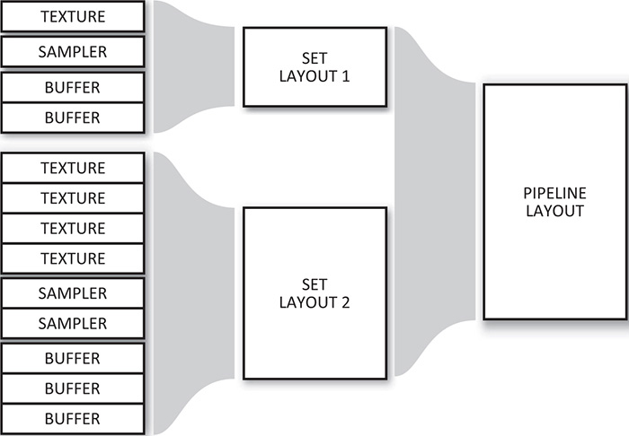
At any time, the application can bind a new descriptor set to the command buffer in any point that has an identical layout. The same descriptor set layouts can be used to create multiple pipelines. Therefore, if you have a set of objects that share a common set of resources, but additionally each require some unique resources, you can leave the common set bound and replace the unique resources as your application moves through the objects that need to be rendered.
To create a descriptor set layout object, call vkCreateDescriptorSetLayout(), the prototype of which is
VkResult vkCreateDescriptorSetLayout (
VkDevice device,
const VkDescriptorSetLayoutCreateInfo* pCreateInfo,
const VkAllocationCallbacks* pAllocator,
VkDescriptorSetLayout* pSetLayout);
As usual, the information required to construct the descriptor set layout object is passed through a pointer to a structure. This is an instance of the VkDescriptorSetLayoutCreateInfo structure, the definition of which is
typedef struct VkDescriptorSetLayoutCreateInfo {
VkStructureType sType;
const void* pNext;
VkDescriptorSetLayoutCreateFlags flags;
uint32_t bindingCount;
const VkDescriptorSetLayoutBinding* pBindings;
} VkDescriptorSetLayoutCreateInfo;
The sType field of VkDescriptorSetLayoutCreateInfo should be set to VK_STRUCTURE_TYPE_DESCRIPTOR_SET_LAYOUT_CREATE_INFO, and pNext should be set to nullptr. flags is reserved for future use and should be set to zero.
Resources are bound to binding points in the descriptor set. The bindingCount and pBindings members of VkDescriptorSetLayoutCreateInfo contain the number of binding points that the set will contain and a pointer to an array containing their descriptions, respectively. Each binding is described by an instance of the VkDescriptorSetLayoutBinding structure, the definition of which is
typedef struct VkDescriptorSetLayoutBinding {
uint32_t binding;
VkDescriptorType descriptorType;
uint32_t descriptorCount;
VkShaderStageFlags stageFlags;
const VkSampler* pImmutableSamplers;
} VkDescriptorSetLayoutBinding;
Each resource accessible to a shader is given a binding number. This binding number is stored in the binding field of VkDescriptorSetLayoutBinding. The bindings used in a descriptor set do not need to be contiguous, and there can be gaps (unused binding numbers) in a set. However, it’s recommended that you don’t create sparsely populated sets because this can waste resources in the device.
The type of descriptor at this binding point is stored in descriptorType. This a member of the VkDescriptorType enumeration. We’ll discuss the various resource types a little later, but they include
• VK_DESCRIPTOR_TYPE_SAMPLER: A sampler is an object that can be used to perform operations such as filtering and sample coordinate transformations when reading data from an image.
• VK_DESCRIPTOR_TYPE_SAMPLED_IMAGE: A sampled image is an image that can be used in conjunction with a sampler to provide filtered data to a shader.
• VK_DESCRIPTOR_TYPE_COMBINED_IMAGE_SAMPLER: A combined image-sampler object is a sampler and an image paired together. The same sampler is always used to sample from the image, which can be more efficient on some architectures.
• VK_DESCRIPTOR_TYPE_STORAGE_IMAGE: A storage image is an image that cannot be used with a sampler but can be written to. This is in contrast to a sampled image, which cannot be written to.
• VK_DESCRIPTOR_TYPE_UNIFORM_TEXEL_BUFFER: A uniform texel buffer is a buffer that is filled with homogeneous formatted data that cannot be written by shaders. Knowing that buffer content is constant may allow some Vulkan implementations to optimize access to the buffer better.
• VK_DESCRIPTOR_TYPE_STORAGE_TEXEL_BUFFER: A storage texel buffer is a buffer that contains formatted data much like a uniform texel buffer, but a storage buffer can be written to.
• VK_DESCRIPTOR_TYPE_UNIFORM_BUFFER and VK_DESCRIPTOR_TYPE_STORAGE_BUFFER: These are similar to VK_DESCRIPTOR_TYPE_UNIFORM_TEXEL_BUFFER and VK_DESCRIPTOR_TYPE_STORAGE_TEXEL_BUFFER, except that the data is unformatted and described by structures declared in the shader.
• VK_DESCRIPTOR_TYPE_UNIFORM_BUFFER_DYNAMIC and VK_DESCRIPTOR_TYPE_STORAGE_BUFFER_DYNAMIC: These are similar to VK_DESCRIPTOR_TYPE_UNIFORM_BUFFER and VK_DESCRIPTOR_TYPE_STORAGE_BUFFER, but include an offset and size that are passed when the descriptor set is bound to the pipeline rather than when the descriptor is bound into the set. This allows a single buffer in a single set to be updated at high frequency.
• VK_DESCRIPTOR_TYPE_INPUT_ATTACHMENT: An input attachment is a special type of image whose content is generated by earlier operations on the same image in a graphics pipeline.
Listing 6.8 illustrates how a selection of resources is declared inside a GLSL shader.
Listing 6.8 : Declaring Resources in GLSL
#version 450 core
layout (set = 0, binding = 0) uniform sampler2DmyTexture;
layout (set = 0, binding = 2) uniform sampler3DmyLut;
layout (set = 1, binding = 0) uniform myTransforms
{
mat4 transform1;
mat3 transform2;
};
void main(void)
{
// Do nothing!
}
Listing 6.9 shows a condensed form of what the shader in Listing 6.8 translates to when compiled with the GLSL compiler.
Listing 6.9: Declaring Resources in SPIR-V
; SPIR-V
; Version: 1.0
; Generator: Khronos Glslang Reference Front End; 1
; Bound: 22
; Schema: 0
OpCapability Shader
%1 = OpExtInstImport "GLSL.std.450"
OpMemoryModel Logical GLSL450
OpEntryPoint GLCompute %4 "main"
OpExecutionMode %4 LocalSize 1 1 1
OpSource GLSL 450
OpName %4 "main"
OpName %10 "myTexture"
OpName %14 "myLut"
OpName %19 "myTransforms"
OpMemberName %19 0 "transform1"
OpMemberName %19 1 "transform2"
OpName %21 ""
OpDecorate %10 DescriptorSet 0
OpDecorate %10 Binding 0
OpDecorate %14 DescriptorSet 0
OpDecorate %14 Binding 2
OpMemberDecorate %19 0 ColMajor
OpMemberDecorate %19 0 Offset 0
OpMemberDecorate %19 0 MatrixStride 16
OpMemberDecorate %19 1 ColMajor
OpMemberDecorate %19 1 Offset 64
OpMemberDecorate %19 1 MatrixStride 16
OpDecorate %19 Block
OpDecorate %21 DescriptorSet 1
OpDecorate %21 Binding 0
%2 = OpTypeVoid
%3 = OpTypeFunction %2
%6 = OpTypeFloat 32
%7 = OpTypeImage %6 2D 0 0 0 1 Unknown
%8 = OpTypeSampledImage %7
%9 = OpTypePointer UniformConstant %8
%10 = OpVariable %9 UniformConstant
%11 = OpTypeImage %6 3D 0 0 0 1 Unknown
%12 = OpTypeSampledImage %11
%13 = OpTypePointer UniformConstant %12
%14 = OpVariable %13 UniformConstant
%15 = OpTypeVector %6 4
%16 = OpTypeMatrix %15 4
%17 = OpTypeVector %6 3
%18 = OpTypeMatrix %17 3
%19 = OpTypeStruct %16 %18
%20 = OpTypePointer Uniform %19
%21 = OpVariable %20 Uniform
%4 = OpFunction %2 None %3
%5 = OpLabel
OpReturn
OpFunctionEnd
Multiple descriptor set layouts can be used in a single pipeline. As you can see in Listings 6.8 and 6.9, the resources are placed in two sets, the first containing "myTexture" and "myLut" (both samplers) and the second containing "myTransforms" (a uniform buffer). To group two or more descriptor sets into something the pipeline can use, we need to aggregate them into a VkPipelineLayout object. To do this, call vkCreatePipelineLayout(), the prototype of which is
VkResult vkCreatePipelineLayout (
VkDevice device,
const VkPipelineLayoutCreateInfo* pCreateInfo,
const VkAllocationCallbacks* pAllocator,
VkPipelineLayout* pPipelineLayout);
This function uses the device specified in device to create a new VkPipelineLayout object using the information in a VkPipelineLayoutCreateInfo structure passed by address in pCreateInfo. The definition of VkPipelineLayoutCreateInfo is
typedef struct VkPipelineLayoutCreateInfo {
VkStructureType sType;
const void* pNext;
VkPipelineLayoutCreateFlags flags;
uint32_t setLayoutCount;
const VkDescriptorSetLayout* pSetLayouts;
uint32_t pushConstantRangeCount;
const VkPushConstantRange* pPushConstantRanges;
} VkPipelineLayoutCreateInfo;
The sType field for VkPipelineLayoutCreateInfo should be set to VK_STRUCTURE_TYPE_PIPELINE_LAYOUT_CREATE_INFO, and pNext should be set to nullptr. The flags field is reserved in the current version of Vulkan and should be set to zero.
The number of descriptor set layouts (which is the same as the number of sets in the pipeline layout) is given in setLayoutCount, and pSetLayouts is a pointer to an array of VkDescriptorSetLayout handles created previously with calls to vkCreateDescriptorSetLayout(). The maximum number of descriptor sets that can be bound at once (and therefore the maximum number of set layouts in a pipeline layout) is at least 4. Some implementations may support a higher limit than this. You can determine the absolute maximum number of layouts supported by inspecting the maxBoundDescriptorSets member of the device’s VkPhysicalDeviceLimits structure, which you can retrieve by calling vkGetPhysicalDeviceProperties().
The final two parameters, pushConstantRangeCount and pPushConstantRanges, are used to describe the push constants used in the pipeline. Push constants are a special class of resource that can be used directly as constants in a shader. It is extremely fast to update the values of push constants, requiring no synchronization. We discuss push constants later in this chapter.
When the VkDescriptorSetLayout object is created, the resources used by all of the sets within the pipeline layout are aggregated and must fall within a device-dependent limit. Effectively, there is an upper bound on the number and type of resources that can be accessed by a single pipeline.
Further, some devices may not support accessing all of the pipeline’s resources from every shader stage simultaneously and therefore have a per-stage upper limit on the number of resources accessible from each stage.
Each of the limits can be checked by retrieving the device’s VkPhysicalDeviceLimits structure through a call to vkGetPhysicalDeviceProperties() and checking the relevant members. The members of VkPhysicalDeviceLimits associated with pipeline layout maximums are shown in Table 6.1.

If your shaders or the resulting pipeline need to use more resources than are guaranteed to be supported as shown in Table 6.1, then you need to check the resource limits and be prepared to fail gracefully if you exceed them. However, if your resource requirements fit comfortably inside this range, there’s no reason to query any of it directly as Vulkan guarantees at least this level of support.
Two pipelines can be used with the same set of descriptor sets if their pipeline layouts are considered to be compatible. For two pipeline layouts to be compatible for descriptor sets, they must
• Use the same number of push constant ranges
• Use the same descriptor set layouts (or identical layouts) in the same order
Two pipeline layouts are also considered to be partially compatible if they use the same (or identically defined) set layouts for the first few sets and then differ after that. In that case, the pipelines are compatible up to the point where the descriptor set layouts change.
When a pipeline is bound to a command buffer, it can continue to use any bound descriptor sets that are compatible with the set bindings in the pipeline layout. Thus, switching between two (partially) compatible pipelines doesn’t require re-binding any sets up to the point where the pipelines share layouts. If you have a set of resources that you want to be globally available, such as a uniform block containing some per-frame constants, or a set of textures that you want to be available to every shader, put those in the first set(s). Resources that might change at higher frequency can be placed in higher-numbered sets.
Listing 6.10 shows the application-side code to create the descriptor set layouts and pipeline layout describing the sets referenced in Listings 6.8 and 6.9.
Listing 6.10: Creating a Pipeline Layout
// This describes our combined image-samplers. One set, two disjoint bindings.
static const VkDescriptorSetLayoutBinding Samplers[] =
{
{
0, // Start from binding 0
VK_DESCRIPTOR_TYPE_COMBINED_IMAGE_SAMPLER, // Combined image-sampler
1, // Create one binding
VK_SHADER_STAGE_ALL, // Usable in all stages
nullptr // No static samplers
},
{
2, // Start from binding 2
VK_DESCRIPTOR_TYPE_COMBINED_IMAGE_SAMPLER, // Combined image-sampler
1, // Create one binding
VK_SHADER_STAGE_ALL, // Usable in all stages
nullptr // No static samplers
}
};
// This is our uniform block. One set, one binding.
static const VkDescriptorSetLayoutBinding UniformBlock =
{
0, // Start from binding 0
VK_DESCRIPTOR_TYPE_UNIFORM_BUFFER, // Uniform block
1, // One binding
VK_SHADER_STAGE_ALL, // All stages
nullptr // No static samplers
};
// Now create the two descriptor set layouts.
static const VkDescriptorSetLayoutCreateInfo createInfoSamplers =
{
VK_STRUCTURE_TYPE_DESCRIPTOR_SET_LAYOUT_CREATE_INFO,
nullptr,
0,
2,
&Samplers[0]
};
static const VkDescriptorSetLayoutCreateInfo createInfoUniforms =
{
VK_STRUCTURE_TYPE_DESCRIPTOR_SET_LAYOUT_CREATE_INFO,
nullptr,
0,
1,
&UniformBlock
};
// This array holds the two set layouts.
VkDescriptorSetLayout setLayouts[2];
vkCreateDescriptorSetLayout(device, &createInfoSamplers,
nullptr, &setLaouts[0]);
vkCreateDescriptorSetLayout(device, &createInfoUniforms,
nullptr, &setLayouts[1]);
// Now create the pipeline layout.
const VkPipelineLayoutCreateInfo pipelineLayoutCreateInfo =
{
VK_STRUCTURE_TYPE_PIPELINE_LAYOUT_CREATE_INFO, nullptr,
0,
2, setLayouts,
0, nullptr
};
VkPipelineLayout pipelineLayout;
vkCreatePipelineLayout(device, &pipelineLayoutCreateInfo,
nullptr, pipelineLayout);
The pipeline layout we create in Listing 6.10 matches the layout expected by the shader code in Listings 6.9 and 6.10. When we create a compute pipeline using that shader, we pass the pipeline layout object created in Listing 6.10 as the layout field of the VkComputePipelineCreateInfo structure passed to vkCreateComputePipelines().
When the pipeline layout is no longer needed, it should be destroyed by calling vkDestroyPipelineLayout(). This frees any resources associated with the pipeline layout object. The prototype of vkDestroyPipelineLayout() is
void vkDestroyPipelineLayout (
VkDevice device,
VkPipelineLayout pipelineLayout,
const VkAllocationCallbacks* pAllocator);
After the pipeline layout object is destroyed, it should not be used again. However, any pipelines created using the pipeline layout object remain valid until they are destroyed. It is therefore not necessary to keep pipeline layout objects around in order to use the pipelines created using them.
To destroy a descriptor set layout object and free its resources, call
void vkDestroyDescriptorSetLayout (
VkDevice device,
VkDescriptorSetLayout descriptorSetLayout,
const VkAllocationCallbacks* pAllocator);
The device that owns the descriptor set layout should be passed in device, and the handle to the descriptor set layout is passed in descriptorSetLayout. pAllocator should point to a host memory allocation structure that is compatible with the one used to create the descriptor set layout or should be nullptr if the pAllocator parameter to vkCreateDescriptorSetLayout() was also nullptr.
After a descriptor set layout is destroyed, its handle is no longer valid, and it should not be used again. However, descriptor sets, pipeline layouts, and other objects created by referencing the set remain valid.
Binding Resources to Descriptor Sets
Resources are represented by descriptors and are bound to the pipeline by first binding their descriptors into sets and then binding those descriptor sets to the pipeline. This allows a large number of resources to be bound with very little processing time because the exact set of resources used by a particular drawing command can be determined in advance and the descriptor set holding them created up front.
The descriptors are allocated from pools called descriptor pools. Because descriptors for different types of resources are likely to have similar data structures on any given implementation, pooling the allocations used to store descriptors allows drivers to make efficient use of memory. To create a descriptor pool, call vkCreateDescriptorPool(), the prototype of which is
VkResult vkCreateDescriptorPool (
VkDevice device,
const VkDescriptorPoolCreateInfo* pCreateInfo,
const VkAllocationCallbacks* pAllocator,
VkDescriptorPool* pDescriptorPool);
The device that is to be used to create the descriptor pool is specified in device, and the remaining parameters describing the new pool are passed through a pointer to an instance of the VkDescriptorPoolCreateInfo structure in pCreateInfo. The definition of VkDescriptorPoolCreateInfo is
typedef struct VkDescriptorPoolCreateInfo {
VkStructureType sType;
const void* pNext;
VkDescriptorPoolCreateFlags flags;
uint32_t maxSets;
uint32_t poolSizeCount;
const VkDescriptorPoolSize* pPoolSizes;
} VkDescriptorPoolCreateInfo;
The sType field of VkDescriptorPoolCreateInfo should be set to VK_STRUCTURE_TYPE_DESCRIPTOR_POOL_CREATE_INFO, and the pNext field should be set to nullptr. The flags field is used to pass additional information about the allocation strategy that should be used to manage the resources consumed by the pool. The only defined flag is VK_DESCRIPTOR_POOL_CREATE_FREE_DESCRIPTOR_SET_BIT, which, if set, indicates that the application may free individual descriptors allocated from the pool, so the allocator should be prepared for that. If you don’t intend to return individual descriptors to the pool, simply set flags to zero.
The maxSets field specifies the maximum total number of sets that may be allocated from the pool. Note that this is the total number of sets, regardless of the size of each set or the overall size of the pool. The next two fields, poolSizeCount and pPoolSize, specify the number of resource descriptors for each type of resoruce that might be stored in the set. pPoolSize is a pointer to an array of poolSizeCount instances of the VkDescriptorPoolSize structure, each one specifying the number of descriptors of a particular type that may be allocated from the pool. The definition of VkDescriptorPoolSize is
typedef struct VkDescriptorPoolSize {
VkDescriptorType type;
uint32_t descriptorCount;
} VkDescriptorPoolSize;
The first field of VkDescriptorPoolSize, type, specifies the type of resource, and the second field, descriptorCount, specifies the number of descriptors of that type to be stored in the pool. type is a member of the VkDescriptorType enumeration. If no element of the pPoolSize array specifies a particular type of resource, then no descriptors of that type can be allocated from the resulting pool. If a particular type of resource appears twice in the array, then the sum of all of their descriptorCount fields is used to size the pool for that type of resource. The total number of resources in the pool is divided among the sets allocated from the pool.
If creation of the pool is successful, then a handle to the new VkDescriptorPool object is written into the variable pointed to by pDescriptorPool. To allocate blocks of descriptors from the pool, we create new descriptor set objects by calling vkAllocateDescriptorSets(), the declaration of which is
VkResult vkAllocateDescriptorSets (
VkDevice device,
const VkDescriptorSetAllocateInfo* pAllocateInfo,
VkDescriptorSet* pDescriptorSets);
The device that owns the descriptor pool from which the sets are to be allocated is passed in device. The remaining information describing the sets to be allocated is passed via a pointer to an instance of the VkDescriptorSetAllocateInfo structure in pDescriptorSets. The definition of VkDescriptorSetAllocateInfo is
typedef struct VkDescriptorSetAllocateInfo {
VkStructureType sType;
const void* pNext;
VkDescriptorPool descriptorPool;
uint32_t descriptorSetCount;
const VkDescriptorSetLayout* pSetLayouts;
} VkDescriptorSetAllocateInfo;
The sType field of the VkDescriptorSetAllocateInfo structure should be set to VK_STRUCTURE_TYPE_DESCRIPTOR_SET_ALLOCATE_INFO, and the pNext field should be set to nullptr. A handle to the descriptor pool from which to allocate the sets is specified in descriptorPool, which should be a handle of a descriptor set created by a call to vkCreateDescriptorPool(). Access to descriptorPool should be externally synchronized. The number of sets to create is specified in descriptorSetCount. The layout of each set is then passed through an array of VkDescriptorSetLayout object handles in pSetLayouts.
When successful, vkAllocateDescriptorSets() consumes sets and descriptors from the specified pool and deposits the new descriptor set handles in the array pointed to by pDescriptorSets. The number of descriptors consumed from the pool for each descriptor set is determined from the descriptor set layouts passed through pSetLayouts, the creation of which we described earlier.
If the descriptor pool was created with the flags member of the VkDescriptorSetCreateInfo structure containing VK_DESCRIPTOR_POOL_CREATE_FREE_DESCRIPTOR_SET_BIT, then descriptor sets may be returned to the pool by freeing them. To free one or more descriptor sets, call vkFreeDescriptorSets(), the prototype of which is
VkResult vkFreeDescriptorSets (
VkDevice device,
VkDescriptorPool descriptorPool,
uint32_t descriptorSetCount,
const VkDescriptorSet* pDescriptorSets);
The device that owns the descriptor pool is specified in device, and the pool to which the descriptor sets should be returned is specified in descriptorPool. Access to descriptorPool must be externally synchronized. The number of descriptor sets to free is passed in descriptorSetCount, and pDescriptorSets points to an array of VkDescriptorSet handles to the objects to free. When the descriptor sets are freed, their resources are returned to the pool from which they came and may be allocated to a new set in the future.
Even if VK_DESCRIPTOR_POOL_CREATE_FREE_DESCRIPTOR_SET_BIT was not specified when a descriptor pool was created, it’s still possible to recycle all the resources from all sets allocated from the pool. This is accomplished by resetting the pool itself by calling vkResetDescriptorPool(). With this command, it’s not necessary to explicitly specify every set allocated from the pool. The prototype of vkResetDescriptorPool() is
VkResult vkResetDescriptorPool (
VkDevice device,
VkDescriptorPool descriptorPool,
VkDescriptorPoolResetFlags flags);
device is a handle to the device that owns the descriptor pool, and descriptorPool is a handle to the descriptor pool being reset. Access to the descriptor pool must be externally synchronized. flags is reserved for future use and should be set to zero.
Regardless of whether sets are individually freed by calling vkFreeDescriptorSets() or freed in bulk by calling vkResetDescriptorPool(), care must be taken to ensure that sets are not referenced after they have been freed. In particular, any command buffer containing commands that might reference descriptor sets that are to be freed should either have completed execution or should be discarded without submission.
To completely free the resources associated with a descriptor pool, you should destroy the pool object by calling vkDestroyDescriptorPool(), the prototype of which is
void vkDestroyDescriptorPool(
VkDevice device,
VkDescriptorPool descriptorPool,
const VkAllocationCallbacks* pAllocator);
A handle to the device that owns the pool should be passed in device, and the handle to the pool to destroy is passed in descriptorPool. pAllocator should point to a host memory allocation structure that is compatible with the one used to create the pool or should be nullptr if the pAllocator parameter to vkCreateDescriptorPool() was also nullptr.
When the descriptor pool is destroyed, all of its resources are freed, including any sets allocated from it. There is no need to explicitly free the descriptor sets allocated from the pool before destroying it or to reset the pool with a call to vkResetDescriptorPool(). However, just as when descriptor sets are freed explicitly, you must make sure that your application does not access sets allocated from a pool after that pool has been destroyed. This includes any work performed by the device during execution of command buffers submitted but not yet completed.
To bind resources into descriptor sets, we can either write to the descriptor set directly or copy bindings from another descriptor set. In either case, we use the vkUpdateDescriptorSets() command, the prototype of which is
void vkUpdateDescriptorSets (
VkDevice device,
uint32_t descriptorWriteCount,
const VkWriteDescriptorSet* pDescriptorWrites,
uint32_t descriptorCopyCount,
const VkCopyDescriptorSet* pDescriptorCopies);
The device that owns the descriptor set to be updated is passed in device. The number of direct writes is passed in descriptorWriteCount, and the number of descriptor copies is passed in descriptorCopyCount. The parameters for each write are contained in a VkWriteDescriptorSet structure, and the parameters for each copy are contained in a VkCopyDescriptorSet structure. The pDescriptorWrites and pDescriptorCopies parameters contain pointers to descriptorWriteCount and descriptorCopyCount VkWriteDescriptorSet and VkCopyDescriptorSet structures, respectively. The definition of VkWriteDescriptorSet is
typedef struct VkWriteDescriptorSet {
VkStructureType sType;
const void* pNext;
VkDescriptorSet dstSet;
uint32_t dstBinding;
uint32_t dstArrayElement;
uint32_t descriptorCount;
VkDescriptorType descriptorType;
const VkDescriptorImageInfo* pImageInfo;
const VkDescriptorBufferInfo* pBufferInfo;
const VkBufferView* pTexelBufferView;
} VkWriteDescriptorSet;
The sType field of VkWriteDescriptorSet should be set to VK_STRUCTURE_TYPE_WRITE_DESCRIPTOR_SET, and pNext should be set to nullptr. For each write operation, the destination descriptor set is specified in dstSet, and the binding index is specified in dstBinding. If the binding in the set refers to an array of resources, then dstArrayElement is used to specify the starting index of the update, and descriptorCount is used to specify the number of consecutive descriptors to update. If the target binding is not an array, then dstArrayElement should be set to 0, and descriptorCount should be set to 1.
The type of resource being updated is specified in descriptorType, which is a member of the VkDescriptorType enumeration. The value of this parameter determines which of the next parameters is considered by the function. If the descriptor being updated is an image resource, then pImageInfo is a pointer to an instance of the VkDescriptorImageInfo structure containing information about the image. The definition of VkDescriptorImageInfo is
typedef struct VkDescriptorImageInfo {
VkSampler sampler;
VkImageView imageView;
VkImageLayout imageLayout;
} VkDescriptorImageInfo;
A handle to the image view that is to be bound into the descriptor set is passed in imageView. If the resource in the descriptor set is a VK_DESCRIPTOR_TYPE_COMBINED_IMAGE_SAMPLER, then a handle to the accompanying sampler is specified in sampler. The layout that the image is expected to be in when it is used in the descriptor set is passed in imageLayout.
If the resource to be bound into the descriptor set is a buffer, then the parameters describing the binding are stored in an instance of the VkDescriptorBufferInfo structure, and a pointer to this structure is stored in the pBufferInfo of VkWriteDescriptorSet. The definition of VkDescriptorBufferInfo is
typedef struct VkDescriptorBufferInfo {
VkBuffer buffer;
VkDeviceSize offset;
VkDeviceSize range;
} VkDescriptorBufferInfo;
The buffer object to bind is specified in buffer, and the offset and size of binding, expressed in bytes, are specified in offset and range, respectively. The bound range must lie entirely inside the buffer object. To bind the whole buffer (inferring the size of the range from the buffer object), then range can be set to VK_WHOLE_SIZE.
If the referenced buffer binding is a uniform buffer binding, then range must be less than or equal to the device’s maxUniformBufferRange limit, as determined by calling vkGetPhysicalDeviceProperties() and inspecting the VkPhysicalDeviceLimits structure. Also, the offset parameter must be an integer multiple of the device’s uniform buffer offset alignment requirement, which is contained in the minUniformBufferOffsetAlignment field of the VkPhysicalDeviceLimits structure. Likewise, if the buffer binding is a storage buffer, then range must be less than or equal to the maxStorageBufferRange field of VkPhysicalDeviceLimits. For storage buffers, the offset parameter must be an integer multiple of the minStorageBufferOffsetAlignment field of the VkPhysicalDeviceLimits structure.
The maxUniformBufferRange and maxStorageBufferRange limits are guaranteed to be at least 16,384 and 227, respectively. If the buffers you’re using fit within these limits, there’s no reason to query them. Note that the guaranteed maximum size of a storage buffer is much larger than that of a uniform buffer. If you have a very large amount of data, it may be worth considering using storage buffers over uniform buffers, even if access to the buffer’s content is uniform in nature.
The minUniformBufferOffsetAlignment and minStorageBufferOffsetAlignment are guaranteed to be at most 256 bytes. Note that these are maximum minimums, and the values reported for a device may be smaller than this.
In addition to writing directly into descriptor sets, vkUpdateDescriptorSets() can copy descriptors from one set to another or between bindings in the same set. These copies are described in the array of VkCopyDescriptorSet structures passed through the pDescriptorCopies parameter. The definition of VkCopyDescriptorSet is
typedef struct VkCopyDescriptorSet {
VkStructureType sType;
const void* pNext;
VkDescriptorSet srcSet;
uint32_t srcBinding;
uint32_t srcArrayElement;
VkDescriptorSet dstSet;
uint32_t dstBinding;
uint32_t dstArrayElement;
uint32_t descriptorCount;
} VkCopyDescriptorSet;
The sType field of VkCopyDescriptorSet should be set to VK_STRUCTURE_TYPE_COPY_DESCRIPTOR_SET, and pNext should be set to nullptr. The handles of the source and destination descriptor sets are specified in the srcSet and dstSet, respectively. These can be the same set so long as the range of descriptors to copy does not overlap.
The srcBinding and dstBinding fields specify the binding indices of the source and destination descriptors, respectively. If the descriptors to be copied form an array of bindings, the indices of the start of the range of descriptors in the source and destination sets are specified in srcArrayElement and dstArrayElement, respectively. If the descriptors do not form arrays, both of these fields should be set to 0. The length of the array of descriptors to copy is specified in descriptorCount. If the copy is not of an array of descriptors, then descriptorCount should be set to 1.
When vkUpdateDescriptorSets() executes, the updates are performed by the host. Any access by the device to the descriptor sets referenced by the pDescriptorWrites or pDescriptorCopies arrays must be complete before vkUpdateDescriptorSets() is called. This includes work described in command buffers that have already been submitted but may not yet have completed execution.
All of the descriptor writes described by pWriteDescriptors are executed first, in the order in which they appear in the array, followed by all of the copies described by pCopyDescriptors. This means that if a particular binding is the destination of a write or copy operation more than once, only the last action on that binding as a destination will be visible after all the operations complete.
Binding Descriptor Sets
Just as with pipelines, to access the resources attached to a descriptor set, the descriptor set must be bound to the command buffer which will execute the commands that access those descriptors. There are also two binding points for descriptor sets—one for compute and one for graphics—which are the sets that will be accessed by the pipelines of the appropriate type.
To bind descriptor sets to a command buffer, call vkCmdBindDescriptorSets(), the prototype of which is
void vkCmdBindDescriptorSets (
VkCommandBuffer commandBuffer,
VkPipelineBindPoint pipelineBindPoint,
VkPipelineLayout layout,
uint32_t firstSet,
uint32_t descriptorSetCount,
const VkDescriptorSet* pDescriptorSets,
uint32_t dynamicOffsetCount,
const uint32_t* pDynamicOffsets);
The command buffer to which the descriptor sets will be bound is specified in commandBuffer. The pipelineBindPoint argument specifies whether to bind the descriptor sets into the compute or graphics binding point by setting it to VK_PIPELINE_BIND_POINT_COMPUTE or VK_PIPELINE_BIND_POINT_GRAPHICS, respectively.
The pipeline layout that will be used by pipelines that will access the descriptors in the set specified in layout. This layout needs to be compatible with any pipeline that will use the sets and allows Vulkan to correctly configure the set bindings before a pipeline is bound to the command buffer. This means that the order in which you bind resources and pipelines into a command buffer doesn’t matter so long as by the time you issue any drawing or dispatch commands, the layouts match.
To bind a subset of the sets accessible to the pipeline layout, use the firstSet and descriptorSetCount arguments to specify the index of the first set to bind and the number of sets, respectively. pDescriptorSets is a pointer to an array of VkDescriptorSet handles to the sets to be bound. These are obtained from calls to vkAllocateDescriptorSets() discussed earlier.
vkCmdBindDescriptorSets() is also responsible for setting the offsets used in any dynamic uniform or shader storage bindings. These are passed in the dynamicOffsetCount and pDynamicOffsets parameters. dynamicOffsetCount is the number of dynamic offsets to set, and pDynamicOffsets is a pointer to an array of dynamicOffsetCount 32-bit offsets. For each dynamic uniform or shader storage buffer in the descriptor set(s) being bound, there should be one offset specified in the pDynamicOffsets array. This offset is added to the base of the buffer view bound to the block in the descriptor set. This allows uniform and shader storage blocks to be re-bound to sections of a larger buffer without needing to create a new buffer view each time the offset is updated. Some implementations may need to pass additional information to the shader to account for this offset, but it is still generally faster than creating buffer views on the fly.
Uniform, Texel, and Storage Buffers
Shaders can access the content of buffer memory directly through three types of resources:
• Uniform blocks provide fast access to constant (read-only) data stored in buffer objects. They are declared as though they were structures in a shader and are attached to memory using a buffer resource bound into the descriptor set.
• Shader storage blocks provide read-write access to buffer objects. Declared similarly to uniform blocks, data is arranged as though it were a structure but can be written to. Shader storage blocks also support atomic operations.
• Texel buffers provide access to long, linear arrays of formatted texel data. They are read-only, and a texel buffer binding performs format conversion from the underlying data format into the floating-point representation that the shader expects when the buffer is read.
Which type of resource you use depends on how you want to access it. The maximum size of a uniform block is often limited, while access to it is generally very fast. On the other hand, the maximum size of a shader storage block is very large, but in some implementations, access to it could be slower—especially if write operations are enabled. For access to large arrays of formatted data, a texel buffer is probably the best choice.
Unform and Shader Storage Blocks
To declare a uniform block in GLSL, use the uniform keyword, as shown in Listing 6.11. A shader storage block is declared similarly, except that the uniform keyword is omitted and the buffer keyword is used instead. The listing shows an example of each. The uniform block uses a descriptor set and binding index that is specified using a GLSL layout qualifier.
Listing 6.11: Declaring Uniform and Shader Blocks in GLSL
layout (set = 0, binding = 1) uniform my_uniform_buffer_t
{
float foo;
vec4 bar;
int baz[42];
} my_uniform_buffer;
layout (set = 0, binding = 2) buffer my_storage_buffer_t
{
int peas;
float carrots;
vec3 potatoes[99];
} my_storage_buffer;
The layout of variables inside the block is determined by a set of rules, which by default follow the std140 rules for uniform blocks and std430 rules for shader storage blocks. These rule sets are named for the version of GLSL in which they were introduced. The set of rules for packing data into memory may be changed by specifying a different layout in GLSL. Vulkan itself, however, does not automatically assign offsets to members of the block. This is the job of the front-end compiler that produces the SPIR-V shader that Vulkan consumes.
The resulting SPIR-V shader must conform to either the std140 or std430 layout rules (the latter being more flexible than the former), although those rules are not explicitly part of the SPIR-V specification. When the declarations are translated to SPIR-V by the front-end compiler, the members of the block are explictly assigned locations. If the shader is generated from something other than GLSL, such as from another high-level language, or programmatically by a component of an application, then so long as the offsets assigned by the SPIR-V generator conform to the appropriate rule set, then the shader will work.
Listing 6.12 shows the shader from Listing 6.11 after it has been translated to SPIR-V by the reference compiler.
Listing 6.12: Declaring Uniform and Shader Blocks in SPIR-V
OpCapability Shader
%1 = OpExtInstImport "GLSL.std.450"
OpMemoryModel Logical GLSL450
OpEntryPoint Vertex %4 "main"
OpSource GLSL 450
OpName %4 "main"
;; Name the my_uniform_buffer_t block and its members.
OpName %12 "my_uniform_buffer_t"
OpMemberName %12 0 "foo"
OpMemberName %12 1 "bar"
OpMemberName %12 2 "baz"
OpName %14 "my_uniform_buffer"
;; Name the my_storage_buffer_t block and its members.
OpName %18 "my_storage_buffer_t"
OpMemberName %18 0 "peas"
OpMemberName %18 1 "carrots"
OpMemberName %18 2 "potatoes"
OpName %20 "my_storage_buffer"
OpDecorate %11 ArrayStride 16
;; Assign offsets to the members of my_uniform_buffer_t.
OpMemberDecorate %12 0 Offset 0
OpMemberDecorate %12 1 Offset 16
OpMemberDecorate %12 2 Offset 32
OpDecorate %12 Block
OpDecorate %14 DescriptorSet 0
OpDecorate %14 Binding 1
OpDecorate %17 ArrayStride 16
;; Assign offsets to the members of my_storage_buffer_t.
OpMemberDecorate %18 0 Offset 0
OpMemberDecorate %18 1 Offset 4
OpMemberDecorate %18 2 Offset 16
OpDecorate %18 BufferBlock
OpDecorate %20 DescriptorSet 0
OpDecorate %20 Binding 2
...
As you can see from Listing 6.12, the compiler has explicitly assigned offsets to each member of the blocks declared in Listing 6.11. Any mention of std140 and std430 is absent from the SPIR-V version of the shader.1
1. std140 and std430 are also absent from the GLSL version of the shader, but they are implied and assumed by the front-end compiler.
Texel Buffers
A texel buffer is a special type of buffer binding used in a shader that can perform format conversion when the data is read. Texel buffers are read-only and are declared in GLSL using a samplerBuffer typed variable, as shown in Listing 6.13. Sampler buffers can return floating-point or signed or unsigned integer data to the shader. An example of each is shown in Listing 6.13.
Listing 6.13: Declaring Texel Buffers in GLSL
layout (set = 0, binding = 3) uniform samplerBuffer my_float_texel_buffer;
layout (set = 0, binding = 4) uniform isamplerBuffer my_signed_texel_buffer;
layout (set = 0, binding = 5) uniform usamplerBuffer my_unsigned_texel_buffer;
When translated to SPIR-V using the reference compiler, the declarations from Listing 6.13 produce the SPIR-V shader shown in Listing 6.14.
Listing 6.14: Declaring Texel Buffers in SPIR-V
OpCapability Shader
OpCapability SampledBuffer
%1 = OpExtInstImport "GLSL.std.450"
OpMemoryModel Logical GLSL450
OpEntryPoint Vertex %4 "main"
OpSource GLSL 450
OpName %4 "main"
;; Name our texel buffers.
OpName %10 "my_float_texel_buffer"
OpName %15 "my_signed_texel_buffer"
OpName %20 "my_unsigned_texel_buffer"
;; Assign set and binding decorations.
OpDecorate %10 DescriptorSet 0
OpDecorate %10 Binding 3
OpDecorate %15 DescriptorSet 0
OpDecorate %15 Binding 4
OpDecorate %20 DescriptorSet 0
OpDecorate %20 Binding 5
%2 = OpTypeVoid
%3 = OpTypeFunction %2
;; Declare the three texel buffer variables.
%6 = OpTypeFloat 32
%7 = OpTypeImage %6 Buffer 0 0 0 1 Unknown
%8 = OpTypeSampledImage %7
%9 = OpTypePointer UniformConstant %8
%10 = OpVariable %9 UniformConstant
%11 = OpTypeInt 32 1
%12 = OpTypeImage %11 Buffer 0 0 0 1 Unknown
%13 = OpTypeSampledImage %12
%14 = OpTypePointer UniformConstant %13
%15 = OpVariable %14 UniformConstant
%16 = OpTypeInt 32 0
%17 = OpTypeImage %16 Buffer 0 0 0 1 Unknown
%18 = OpTypeSampledImage %17
%19 = OpTypePointer UniformConstant %18
%20 = OpVariable %19 UniformConstant
...
To fetch from a texel buffer in GLSL, the texelFetch function is used with the sampler variable to read individual texels. A samplerBuffer (or the corresponding signed or unsigned integer variants, isamplerBuffer and usamplerBuffer) can be thought of as a 1D texture that supports only point sampling. However, the maximum size of a texel buffer attached to one of these variables is generally much, much larger than the maximum size of a 1D texture. For example, the minimum required upper bound for a texel buffer in Vulkan is 65,535 elements, whereas the minimum required size for a 1D texture is only 4,096 texels. In some cases, implementations will support texel buffers that are gigabytes in size.
Push Constants
One special type of resource briefly introduced earlier is the push constant. A push constant is a uniform variable in a shader that can be used just like a member of a uniform block, but rather than being backed by memory, it is owned and updated by Vulkan itself.2 As a consequence, new values for these constants can be pushed into the pipeline directly from the command buffer, hence the term.
2. In reality, some implementations may still back push constants with device memory internally. However, it is likely that such implementations will have more optimal paths for updating that memory; some implementations will have fast, dedicated memory or registers for these constants; and a single call to vkCmdPushConstants() is likely to perform better than memory barriers associated with updating a uniform block in any case.
Push constants are logically considered to be part of the pipeline’s resources and are therefore declared along with the other resources in the pipeline layout used to create pipeline objects. In the VkPipelineLayoutCreateInfo structure, two fields are used to define how many push constants will be used by the pipeline. Push constants belong to ranges, each defined by a VkPushConstantRange structure. The pushConstantRanges member of VkPipelineLayoutCreateInfo specifies the count of the number of ranges of push constants that are included in the pipeline’s resource layout, and the pPushConstantRanges of VkPipelineLayoutCreateInfo is a pointer to an array of VkPushConstantRange structures, each defining a range of push constants used by the pipeline. The definition of VkPushConstantRange is
typedef struct VkPushConstantRange {
VkShaderStageFlags stageFlags;
uint32_t offset;
uint32_t size;
} VkPushConstantRange;
The space used for push constants is abstracted as though it were a contiguous region of memory, even if that may not be the case in practice in some implementations. In some implementations, each shader stage has its own space for constant storage, and in such implementations, passing a single constant to multiple shading stages may require broadcasting it and consuming more resources. The stages that will “see” each range of constants are included in the stageFlags field of VkPushConstantRange. This is a bitwise combination of a selection of flags from VkShaderStageFlagBits. The starting offset and size of the region are specified in offset and size, respectively.
To consume push constants inside the pipeline, variables representing them are declared in the pipeline’s shaders. A push constant is declared in a SPIR-V shader using the PushConstant storage class on a variable declaration. In GLSL, such a declaration can be produced by declaring a uniform block with the push_constant layout qualifier. There is one such block declaration available per pipeline. Logically, it has the same “in-memory” layout as a std430 block. However, this layout is used only to compute offsets to members and may not be how a Vulkan implementation internally represents the data in the block.
Listing 6.15 shows a GLSL declaration of a push constant block, and Listing 6.16 shows the resulting SPIR-V.
Listing 6.15: Declaring Push Constants in GLSL
layout (push_constant) uniform my_push_constants_t
{
int bourbon;
int scotch;
int beer;
} my_push_constants;
Listing 6.16: Declaring Push Constants in SPIR-V
OpCapability Shader
%1 = OpExtInstImport "GLSL.std.450"
OpMemoryModel Logical GLSL450
OpEntryPoint GLCompute %4 "main"
OpExecutionMode %4 LocalSize 1 1 1
OpSource GLSL 450
OpName %4 "main"
;; Name the push constant block and its members.
OpName %7 "my_push_constants_t"
OpMemberName %7 0 "bourbon"
OpMemberName %7 1 "scotch"
OpMemberName %7 2 "beer"
OpName %9 "my_push_constants"
;; Assign offsets to the members of the push constant block.
OpMemberDecorate %7 0 Offset 0
OpMemberDecorate %7 1 Offset 4
OpMemberDecorate %7 2 Offset 8
OpDecorate %7 Block
%2 = OpTypeVoid
%3 = OpTypeFunction %2
%6 = OpTypeInt 32 1
%7 = OpTypeStruct %6 %6 %6
;; Declare the push constant block itself.
%8 = OpTypePointer PushConstant %7
%9 = OpVariable %8 PushConstant
...
Push constants become part of the layout of the pipeline that will use them. When push constants are included in a pipeline, they may consume some of the resources that Vulkan would otherwise use to track pipeline or descriptor bindings. Therefore, you should treat push constants as relatively precious resources.
To update the content of one or more push constants, call vkCmdPushConstants(), the prototype of which is
void vkCmdPushConstants (
VkCommandBuffer commandBuffer,
VkPipelineLayout layout,
VkShaderStageFlags stageFlags,
uint32_t offset,
uint32_t size,
const void* pValues);
The command buffer that will perform the update is specified in commandBuffer, and the layout that defines the locations of the push constants is specified in layout. This layout must be compatible with any pipeline that is subsequently bound and used in dispatch or drawing commands.
The stages that will need to see the updated constants should be specified in stageFlags. This is a bitwise combination of some of the flags from the VkShaderStageFlagBits enumeration. Although there is only one push constant block available to each pipeline, it may be that in some implementations, push constants are implemented by using per-stage resources. When stageFlags is set accurately, performance may increase by allowing Vulkan to not update the stages that aren’t included. Be careful, though: In implementations that do support broadcasting constants across stages at no cost, these flags might be ignored, and your shaders may see the updates anyway.
As push constants are logically represented as backed by memory with a std430 layout, the content of each push constant “lives” at an offset from the beginning of the block that can be computed using the std430 rules. The offset of the first constant to update within this virtual block is specified in offset, and the size of the update, in bytes, is specified in size.
A pointer to the data to place in the push constants is passed in pValues. Typically, this will be a pointer to an array of uint32_t or float variables. Both offset and size must be a multiple of 4 to align them correctly with respect to the size of these data types. When vkCmdPushConstants() is executed, it is as though the contents of the array were copied directly into a std430 block.
You are free to replace the content of the array or free the memory immediately after calling vkCmdPushConstants(). The data in the array is consumed immediately by the command, and the value of the pointer is not retained. Therefore, it’s perfectly fine to set pValues to something that lives on the stack or to the address of a local variable.
The total amount of space available for push constants in a single pipeline (or pipeline layout) can be determined by inspecting the maxPushConstantsSize field of the device’s VkPhysicalDeviceLimits structure. This is guaranteed to be at least 128 bytes (enough for a couple of 4 × 4 matrices). It’s not particularly large, but if this is sufficient, there’s no reason to query the limit. Again, treat push constants as scarce resources. Prefer to use a normal uniform block for larger data structures, and use push constants for single integers or very frequently updated data.
Sampled Images
When shaders read from images, they can do so in one of two ways. The first is to perform a raw load, which directly reads formatted or unformatted data from a specific location in the image, and the second is to sample the image using a sampler. Sampling can include operations such as performing basic transformations on the image coordinates or filtering texels to smooth the image data returned to the shader.
The state of a sampler is represented by a sampler object, which is bound into descriptor sets just as images and buffers are. To create a sampler object, call vkCreateSampler(), the prototype of which is
VkResult vkCreateSampler (
VkDevice device,
const VkSamplerCreateInfo* pCreateInfo,
const VkAllocationCallbacks* pAllocator,
VkSampler* pSampler);
The device that will create the sampler is passed in device, and the remaining parameters of the sampler are passed through a pointer to an instance of the VkSamplerCreateInfo structure in pCreateInfo. The upper bound on the total number of samplers that can be created by a device is implementation-dependent. It’s guaranteed to be at least 4,000. If there’s a possibility that your application may create more than this limit, then you need to check the device’s level of support for creating large numbers of samplers. The total number of samplers that a device can manage is contained in the maxSamplerAllocationCount field of its VkPhysicalDeviceLimits structure, which you can obtain from a call to vkGetPhysicalDeviceProperties().
The definition of VkSamplerCreateInfo is
typedef struct VkSamplerCreateInfo {
VkStructureType sType;
const void* pNext;
VkSamplerCreateFlags flags;
VkFilter magFilter;
VkFilter minFilter;
VkSamplerMipmapMode mipmapMode;
VkSamplerAddressMode addressModeU;
VkSamplerAddressMode addressModeV;
VkSamplerAddressMode addressModeW;
float mipLodBias;
VkBool32 anisotropyEnable;
float maxAnisotropy;
VkBool32 compareEnable;
VkCompareOp compareOp;
float minLod;
float maxLod;
VkBorderColor borderColor;
VkBool32 unnormalizedCoordinates;
} VkSamplerCreateInfo;
The sType field of VkSamplerCreateInfo should be set to VK_STRUCTURE_TYPE_SAMPLER_CREATE_INFO, and pNext should be set to nullptr. The flags field is reserved for future use and should be set to zero.
Image Filtering
The magFilter and minFilter fields specify the filtering mode to be used when the image is magnified or minified, respectively. Whether an image is magnified or minified is determined by comparing sampling coordinates across adjacent pixels being shaded. If the gradient of the sampling coordinates is greater than one, then the image is minified; otherwise, it is magnified. magFilter and minFilter are both members of the VkFilter enumeration. The members of VkFilter are
• VK_FILTER_NEAREST: When sampling, the nearest texel in the image is chosen and returned directly to the shader.
• VK_FILTER_LINEAR: A 2 × 2 footprint containing the texel coordinates is used to produce a weighted average of four texels, and this average is returned to the shader.
The VK_FILTER_NEAREST mode causes Vulkan to simply select the nearest texel to the requested coordinates when sampling from an image. In many cases, this can lead to a blocky or aliased image, causing shimmering artifacts in the rendered picture. The VK_FILTER_LINEAR mode tells Vulkan to apply linear filtering to the image when it is sampled.
When you are filtering an image with linear filtering, the requested sample may lie somewhere between two texel centers in 1D, four centers in 2D, and so on. Vulkan will read from the surrounding texels and then combine the results using a weighted sum of the values based on the distance to each center. This is illustrated in Figure 6.2. In the figure, a sample is taken at the ×, which lies between the four texel centers marked A, B, C, and D. Regardless of the integer part of the texture coordinate {u, v}, the fractional part of the texture coordinate is given by {α, β}.
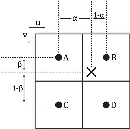
To form a linear weighted sum of the texels at A and B, their values are simply combined according to the relationship
Tu0 = αA + (1 −α) B
This can be writen as
Tu0 = B + α (B−A)
Likewise, a weighted sum of C and D is formed as
Tu1 = αC + (1 −α) D or
Tu1 = D−α (D−C)
The two temporary values Tu0 and Tu1 can then be combined into a single, weighted sum using a similar mechanism, but with β:
T = βTu0 + (1 −β) Tu1 or
T = Tu1 + β(Tu1 −Tu0)
This can be extended in any number of dimensions, although only texture dimensionalities up to three are defined by Vulkan.
Mipmapping
The mipmapMode field specifies how mipmaps are used in the image when it is sampled. This is a member of the VkSamplerMipmapMode enumeration, whose members have the following meanings:
• VK_SAMPLER_MIPMAP_MODE_NEAREST: The computed level-of-detail is rounded to the nearest integer, and that level is used to select the mipmap level. If sampling from the base level, then the filtering mode specified in magFilter is used to sample from that level; otherwise, the minFilter filter is used.
• VK_SAMPLER_MIPMAP_MODE_LINEAR: The computed level of detail is rounded both up and down, and the two resulting mipmap levels are sampled. The two resulting texel values are then blended and returned to the shader.
To select a mipmap from the image, Vulkan will compute the derivative of the coordinates used to sample from the texture. The exact math is covered in some detail in the Vulkan specification. In short, the level selected is the log2 of the maximum of the derivatives of each of the texture coordinate dimensions. This level can also be biased using parameters taken from the sampler or supplied by the shader, or it can be entirely specified in the shader. Regardless of its source, the result may not be an exact integer.
When the mipmap mode is VK_SAMPLER_MIPMAP_MODE_NEAREST, then the selected mipmap level is simply rounded down to the next-lowest integer, and then that level is sampled as though it were a single-level image. When the mipmap mode is VK_SAMPLER_MIPMAP_MODE_LINEAR, a sample is taken from each of the next-lower and next-higher levels using the filtering mode selected by the minFilter field, and then those two samples are further combined using a weighted average, similarly to how the samples are combined during linear sampling, as described earlier.
Note that this filtering mode applies only to minification, which is the process of sampling from a mipmap level other than the base level. When the log2 of the texture coordinate derivatives is less than 1, then the 0th level is selected, so only a single level is available for sampling. This is known as magnification and uses the filtering mode specified in magFilter to sample from the base level only.
The next three fields in VkSamplerCreateInfo—addressModeU, addressModeV, and addressModeW—are used to select the transform that is applied to texture coordinates that would otherwise sample outside the image. The following modes are available:
• VK_SAMPLER_ADDRESS_MODE_REPEAT: As the texture coordinate progresses from 0.0 to 1.0 and beyond, it is wrapped back to 0.0, effectively using only the fractional part of the coordinate to sample from the image. The effect is to tile the image indefinitely.
• VK_SAMPLER_ADDRESS_MODE_MIRRORED_REPEAT: The texture coordinate progresses from 0.0 to 1.0 as normal, and then in the range 1.0 to 2.0, the fractional part is subtracted from 1.0 to form a new coordinate moving back toward 0.0. The effect is to alternately tile the normal and mirror-image version of a texture.
• VK_SAMPLER_ADDRESS_MODE_CLAMP_TO_EDGE: Texture coordinates beyond 1.0 are clamped to 1.0, and negative coordinates are clamped to 0.0. This clamped coordinate is used to sample from the image. The effect is that the texels along the edge of the image are used to fill any area that would be sampled outside the image.
• VK_SAMPLER_ADDRESS_MODE_CLAMP_TO_BORDER: Sampling from the texture outside its bounds will result in texels of the border color, as specified in the borderColor field, being returned rather than data from the image.
• VK_SAMPLER_ADDRESS_MODE_MIRROR_CLAMP_TO_EDGE: This is a hybrid mode that first applies a single mirroring of the texture coordinate and then behaves like VK_SAMPLER_ADDRESS_MODE_CLAMP_TO_EDGE.
The effect of each of the sampler addressing modes applied to an image is shown in Figure 6.3. In the figure, the top-left image shows the result of the VK_SAMPLER_ADDRESS_MODE_REPEAT addressing mode. As you can see, the texture is simply repeated across the frame. The top-right image shows the result of VK_SAMPLER_ADDRESS_MODE_MIRRORED_REPEAT. Each alternate repetition of the texture is mirrored in the X or Y direction.
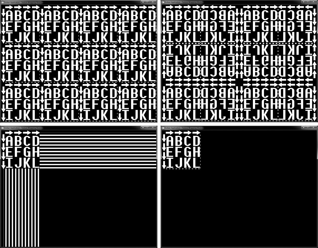
The bottom-left image applies the VK_SAMPLER_ADDRESS_MODE_CLAMP_TO_EDGE addressing mode to the texture. Here, the last column or row of pixels is repeated indefinitely after the sampling coordinates leave the texture. Finally, the bottom-right image shows the result of the VK_SAMPLER_ADDRESS_MODE_CLAMP_TO_BORDER mode. This texture was created with a black border color, so the area outside the texture appears to be blank, but Vulkan is actually sampling black texels from this region. This allows you to see the original texture.
When the filter mode is VK_FILTER_LINEAR, wrapping or clamping the texture coordinate is applied to each of the generated coordinates in the 2 × 2 footprint used to create the resulting texel. The result is that filtering is applied as though the image really wrapped.
For the VK_SAMPLER_ADDRESS_MODE_CLAMP_TO_BORDER filter mode, when texels are sampled from the border (i.e., what would be outside the image), the border color is substituted rather than fetching data from the image. The color that is used depends on the value of the borderColor field. This is not a full color specification, but a member of the VkBorderColor enumeration, which allows one of a small, predefined set of colors to be selected. These are
• VK_BORDER_COLOR_FLOAT_TRANSPARENT_BLACK: Returns floating-point zeros to the shader in all channels
• VK_BORDER_COLOR_INT_TRANSPARENT_BLACK: Returns integer zeros to the shader in all channels
• VK_BORDER_COLOR_FLOAT_OPAQUE_BLACK: Returns floating-point zeros in the R, G, and B channels, and floating-point one in A
• VK_BORDER_COLOR_INT_OPAQUE_BLACK: Returns integer zeros in R, G, and B, and integer one in A
• VK_BORDER_COLOR_FLOAT_OPAQUE_WHITE: Returns floating-point ones to the shader in all channels
• VK_BORDER_COLOR_INT_OPAQUE_WHITE: Returns integer ones to the shader in all channels
The mipLodBias field of VkSamplerCreateInfo specifies a floating-point bias that is added to the computed level of detail before mipmap selection is made. This allows you to nudge the level of detail up or down the mipmap chain to make the resulting filtered texture look sharper or blurrier than it might otherwise.
If you want to use anisotropic filtering, set anisotropyEnable to VK_TRUE. The exact details of anisotropic filtering are implementation-dependent. Anisotropic filtering generally works by considering a projected footprint of the area to be sampled rather than using a fixed 2 × 2 footprint. An approximation to an area sample is formed by taking many samples within the footprint.
Because the number of samples taken can be quite large, anisotropic filtering can have a negative effect on performance. Also, under extreme cases, the projected footprint can be quite large, and this can result in a large area and correspondingly blurry filter result. To limit these effects, you can clamp the maximum amount of anisotropy by setting maxAnisotropy to a value between 1.0 and the maximum value supported by the device. You can determine this by calling vkGetPhysicalDeviceProperties() and inspecting the maxSamplerAnisotropy member of the embedded VkPhysicalDeviceLimits structure.
When a sampler is used with a depth image, it can be configured to perform a comparison operation and return the result of the comparison rather than the raw values stored in the image. When this mode is enabled, the comparison is performed on each sample taken from the image, and the resulting value is the fraction of the total samples taken that passed the test. This can be used to implement a technique known as percentage closer filtering, or PCF. To enable this mode, set compareEnable to VK_TRUE, and set the comparison operation in compareOp.
compareOp is a member of the VkCompareOp enumeration, which is used in many places in Vulkan. As you will see in Chapter 7, “Graphics Pipelines,” this is the same enumeration that is used to specify the depth test operation. The available operations and how they are interpreted in the context of shader accesses to depth resources are shown in Table 6.2.
The sampler can be configured to restrict sampling to a subset of the mip levels in an image with mipmaps. The range of mipmaps to sample from is specified in minLod and maxLod, which contain the lowest (highest-resolution) and highest (lowest-resolution) mipmaps that should be sampled from, respectively. To sample from the entire mipmap chain, set minLod to 0.0, and set maxLod to a level of detail high enough that the computed level of detail will never be clamped.
Finally, unnormalizedCoordinates is a flag that, when set to VK_TRUE, indicates that the coordinates used to sample from the image are in units of raw texels, rather than a value that is normalized between 0.0 and 1.0 across each dimension of the texture. This allows texels to be explicitly fetched from the image. However, several restrictions exist in this mode. When unnormalizedCoordinates is VK_TRUE, minFilter and magFilter must be the same, mipmapMode must be VK_SAMPLER_MIPMAP_MODE_NEAREST, and anisotropyEnable and compareEnable must be VK_FALSE.
When you are done with a sampler, you should destroy it by calling vkDestroySampler(), the prototype of which is
void vkDestroySampler (
VkDevice device,
VkSampler sampler,
const VkAllocationCallbacks* pAllocator);
device is the device that owns the sampler object, and sampler is the sampler object to destroy. If a host memory allocator was used when the sampler was created, a compatible allocator should be passed through the pAllocator parameter; otherwise, pAllocator should be nullptr.
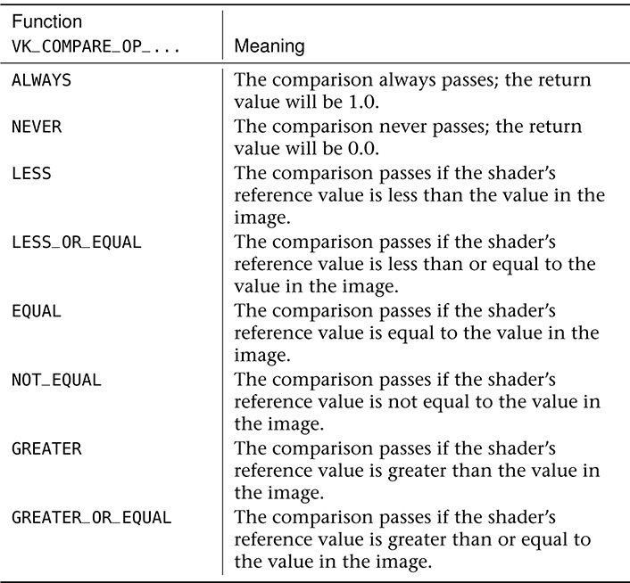
Summary
This chapter covered the basics of the shading language supported by Vulkan, SPIR-V, including how SPIR-V shader modules are consumed by Vulkan and how pipelines containing those shaders are constructed. You saw how to construct a compute shader and use it to create a compute pipeline, how to dispatch work into that pipeline, and how a pipeline can access resources in order to consume and produce data. In upcoming chapters, we will build on the concept of pipelines to produce pipeline objects with multiple stages and make use of more advanced features.