
Chapter 7. Graphics Pipelines
What You’ll Learn in This Chapter
• What the Vulkan graphics pipeline looks like
• How to create a graphics pipeline object
• How to draw graphical primitives with Vulkan
Perhaps the most common use of Vulkan is as a graphics API. Graphics are a fundamental part of Vulkan and drive the core of almost any visual application. Graphics processing in Vulkan can be seen as a pipeline that takes graphics commands through the many stages required to produce a picture on a display. This chapter covers the basics of graphics pipelines in Vulkan and introduces our first graphics example.
The Logical Graphics Pipeline
The graphics pipeline in Vulkan can be seen as a production line, where commands enter the front of the pipeline and are processed in stages. Each stage performs some kind of transform, taking the commands and their associated data and turning them into something else. By the end of the pipeline, the commands have been transformed into colorful pixels making up your output picture.
Many parts of the graphics pipeline are optional and can be disabled or might not even be supported by a Vulkan implementation. The only part of the pipeline that an application must enable is the vertex shader. The full Vulkan graphics pipeline is shown in Figure 7.1. However, don’t be alarmed; we’ll introduce each stage gently in this chapter and dig into more details in subsequent parts of the book.
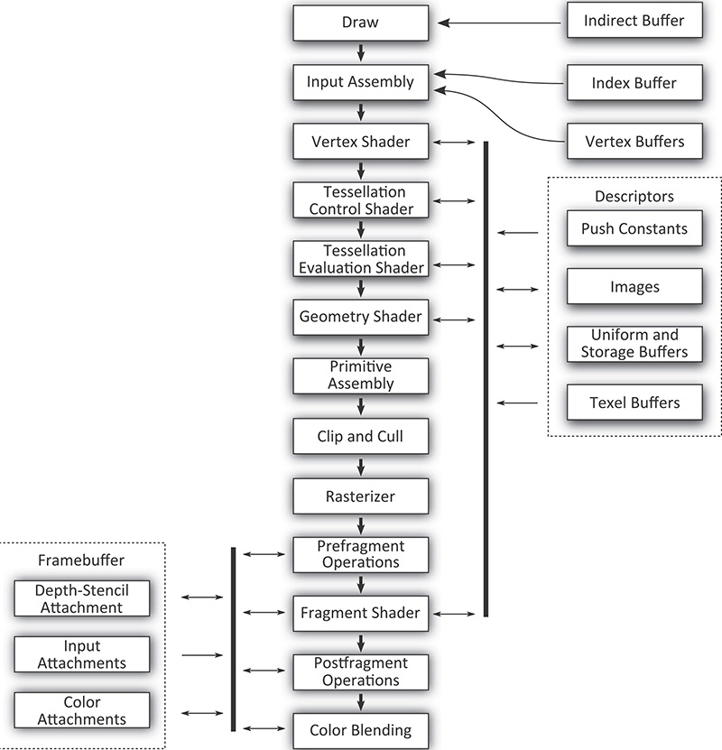
The following is a brief description of each stage of the pipeline and what it does.
• Draw: This is where your commands enter the Vulkan graphics pipeline. Typically, a small processor or dedicated piece of hardware inside the Vulkan device interprets the commands in the command buffer and directly interacts with the hardware to induce work.
• Input assembly: This stage reads the index and vertex buffers that contain information about the vertices making up the draw you’ve sent.
• Vertex shader: This is where the vertex shader executes. It takes as input the properties of the vertex and prepares transformed and processed vertex data for the next stage.
• Tessellation control shader: This programmable shading stage is responsible for producing tessellation factors and other per-patch data that is used by the fixed-function tessellation engine.
• Tessellation primitive generation: Not shown in Figure 7.1, this fixed function stage uses the tessellation factors produced in the tessellation control shader to break patch primitives into many smaller, simpler primitives ready to be shaded by the tessellation evaluation shader.
• Tessellation evaluation shader: This shading stage runs on each new vertex produced by the tessellation primitive generator. It operates similarly to a vertex shader except that the incoming vertices are generated rather than read from memory.
• Geometry shader: This shading stage operates on full primiitves. The primitives might be points, lines or triangles, or special variations of them that include additional vertices surrounding them. This stage also has the ability to change the primitive type midpipeline.
• Primitive assembly: This stage groups vertices produced by the vertex, tessellation, or geometry stage and groups them into primitives suitable for rasterization. It also culls and clips primitives and transforms them into the appropriate viewport.
• Clip and cull: This fixed-function stage determines which parts of which primitives might contribute to the output image and discards parts of primitives that do not, forwarding potentially visible primitives to the rasterizer.
• Rasterizer: Rasterization is the fundamental core of all graphics in Vulkan. The rasterizer takes assembled primitives that are still represented by a sequence of vertices and turns them into individual fragments, which may become the pixels that make up your image.
• Prefragment operations: Several operations can be performed on fragments once their positions are known but before they are shaded. These prefragment operations include depth and stencil tests when they are enabled.
• Fragment assembly: Not shown in the figure, the fragment assembly stage takes the output of the rasterizer along with any per-fragment data and sends it, as a group, into the fragment shading stage.
• Fragment shader: This stage runs the final shader in the pipeline, which is responsible for computing the data that will be sent on to the final fixed-function processing stages that follow.
• Postfragment operations: In some circumstances, the fragment shader modifies data that would normally be used in prefragment operations. In these cases, those prefragment operations move to the postfragment stage and are executed here.
• Color blending: The color operations take the final results of the fragment shader and postfragment operations and use them to update the framebuffer. The color operations include blending and logic operations.
As you can tell, there are a lot of interrelated stages in the graphics pipeline. Unlike the compute pipeline introduced in Chapter 6, “Shaders and Pipelines,” the graphics pipeline contains not only the configuration of a wide selection of fixed functionality, but also up to five shader stages. Further, depending on the implementation, some of the logically fixed-function stages are actually at least partially implemented in shader code generated by drivers.
The purpose of representing the graphics pipeline as an object in Vulkan is to provide the implementation as much information as needed to move parts of the pipeline between fixed-function hardware and programmable shader cores. If the information were not all available at the same time in the same object, it would mean that some implementations of Vulkan may need to recompile a shader based on configurable state. The set of states contained in the graphics pipeline has been carefully chosen to prevent this, making switching states as fast as possible.
The fundamental unit of drawing in Vulkan is a vertex. Vertices are grouped into primitives and processed by the Vulkan pipeline. The simplest drawing command in Vulkan is vkCmdDraw(), whose prototype is
void vkCmdDraw (
VkCommandBuffer commandBuffer,
uint32_t vertexCount,
uint32_t instanceCount,
uint32_t firstVertex,
uint32_t firstInstance);
Like other Vulkan commands, vkCmdDraw() appends a command to a command buffer that will later be executed by the device. The command buffer to append to is specified in commandBuffer. The number of vertices to push into the pipeline is specified in vertexCount. If you want to draw the same set of vertices over and over with slightly different parameters, you can specify the number of instances in instanceCount. This is known as instancing, and we’ll cover that later in this chapter. For now, we can just set instanceCount to 1. It’s also possible to start drawing from a vertex or instance other than 0. To do this, we can use firstVertex and firstInstance, respectively. Again, we’ll cover that later. For the time being, we’ll set both of these parameters to 0.
Before you can draw anything, you must bind a graphics pipeline to the command buffer, and before that, you must create a graphics pipeline. Undefined behavior (generally bad behavior) will occur if you try drawing without binding a pipeline first.
When you call vkCmdDraw(), vertexCount vertices are generated and pushed into the current Vulkan graphics pipeline. For each vertex, input assembly is executed, followed by your vertex shader. Declaring inputs beyond what is provided for you by Vulkan is optional, but having a vertex shader is not. Thus, the simplest possible graphics pipeline consists only of a vertex shader.
Renderpasses
One of the things that distinguishes a Vulkan graphics pipeline from a compute pipeline is that, usually, you’ll be using the graphics pipeline to render pixels into images that you will either further process or display to the user. In complex graphics applications, the picture is built up over many passes where each pass is responsible for producing a different part of the scene, applying full-frame effects such as postprocessing or composition, rendering user interface elements, and so on.
Such passes can be represented in Vulkan using a renderpass object. A single renderpass object encapsulates multiple passes or rendering phases over a single set of output images. Each pass within the renderpass is known as a subpass. Renderpass objects can contain many subpasses, but even in simple applications with only a single pass over a single output image, the renderpass object contains information about that output image.
All drawing must be contained inside a renderpass. Further, graphics pipelines need to know where they’re rendering to; therefore, it’s necessary to create a renderpass object before creating a graphics pipeline so that we can tell the pipeline about the images it’ll be producing. Renderpasses are covered in great depth in Chapter 13, “Multipass Rendering.” In this chapter, we’ll create the simplest possible renderpass object that will allow us to render into an image.
To create a renderpass object, call vkCreateRenderPass(), the prototype of which is
VkResult vkCreateRenderPass (
VkDevice device,
const VkRenderPassCreateInfo* pCreateInfo,
const VkAllocationCallbacks* pAllocator,
VkRenderPass* pRenderPass);
The device parameter to vkCreateRenderPass() is the device that will create the renderpass object, and pCreateInfo points to a structure defining the renderpass. This is an instance of the VkRenderPassCreateInfo structure, whose definition is
typedef struct VkRenderPassCreateInfo {
VkStructureType sType;
const void* pNext;
VkRenderPassCreateFlags flags;
uint32_t attachmentCount;
const VkAttachmentDescription* pAttachments;
uint32_t subpassCount;
const VkSubpassDescription* pSubpasses;
uint32_t dependencyCount;
const VkSubpassDependency* pDependencies;
} VkRenderPassCreateInfo;
The sType field of VkRenderPassCreateInfo should be set to VK_STRUCTURE_TYPE_RENDERPASS_CREATE_INFO, and pNext should be set to nullptr. The flags field is reserved for future use and should be set to zero.
pAttachments is a pointer to an array of attachmentCount VkAttachmentDescription structures that define the attachments associated with the renderpass. Each of these structures defines a single image that is to be used as an input, output, or both within one or more of the subpasses in the renderpass. If there really are no attachments associated with the renderpass, you can set attachmentCount to zero and pAttachments to nullptr. However, outside of some advanced use cases, almost all graphics rendering will use at least one attachment. The definition of VkAttachmentDescription is
typedef struct VkAttachmentDescription {
VkAttachmentDescriptionFlags flags;
VkFormat format;
VkSampleCountFlagBits samples;
VkAttachmentLoadOp loadOp;
VkAttachmentStoreOp storeOp;
VkAttachmentLoadOp stencilLoadOp;
VkAttachmentStoreOp stencilStoreOp;
VkImageLayout initialLayout;
VkImageLayout finalLayout;
} VkAttachmentDescription;
The flags field is used to give Vulkan additional information about the attachment. The only defined bit is VK_ATTACHMENT_DESCRIPTION_MAY_ALIAS_BIT, which, if set, indicates that the attachment might be using the same memory as another attachment referenced by the same renderpass. This tells Vulkan not to do anything that might make data in that attachment inconsistent. This bit can be used in some advanced cases where memory is at a premium and you are trying to optimize its usage. In most cases, flags can be set to zero.
The format field specifies the format of the attachment. This is one of the VkFormat enumerations and should match the format of the image used as the attachment. Likewise, samples indicates the number of samples in the image and is used for multisampling. When multisampling is not in use, set samples to VK_SAMPLE_COUNT_1_BIT.
The next four fields specify what to do with the attachment at the beginning and end of the renderpass. The load operations tell Vulkan what to do with the attachment when the renderpass begins. This can be set to one of the following values:
• VK_ATTACHMENT_LOAD_OP_LOAD indicates that the attachment has data in it already and that you want to keep rendering to it. This causes Vulkan to treat the contents of the attachment as valid when the renderpass begins.
• VK_ATTACHMENT_LOAD_OP_CLEAR indicates that you want Vulkan to clear the attachment for you when the renderpass begins. The color to which you want to clear the attachments is specified when the renderpass has begun.
• VK_ATTACHMENT_LOAD_OP_DONT_CARE indicates that you don’t care about the content of the attachment at the beginning of the renderpass and that Vulkan is free to do whatever it wishes with it. You can use this if you plan to explicitly clear the attachment or if you know that you’ll replace the content of the attachment inside the renderpass.
Likewise, the store operations tell Vulkan what you want it to do with the contents of the attachments when the renderpass ends. These can be set to one of the following values:
• VK_ATTACHMENT_STORE_OP_STORE indicates that you want Vulkan to keep the contents of the attachment for later use, which usually means that it should write them out into memory. This is usually the case for images you want to display to the user, read from later, or use as an attachment in another renderpass (with the VK_ATTACHMENT_LOAD_OP_LOAD load operation).
• VK_ATTACHMENT_STORE_OP_DONT_CARE indicates that you don’t need the content after the renderpass has ended. This is normally used for intermediate storage or for the depth or stencil buffers.
If the attachment is a combined depth-stencil attachment, then the stencilLoadOp and stencilStoreOp fields tell Vulkan what to do with the stencil part of the attachment (the regular loadOp and storeOp fields specify what should happen to the depth part of the attachment), which can be different from the depth part.
The initialLayout and finalLayout fields tell Vulkan what layout to expect the image to be in when the renderpass begins and what layout to leave it in when the renderpass ends. Note that renderpass objects do not automatically move images into the initial layout. This is the layout that the image is expected to be in when the renderpass is used. The renderpass does, however, move the image to the final layout when it’s done.
You can use barriers to explicitly move images from layout to layout, but where possible, it’s best to try to move images from layout to layout inside renderpasses. This gives Vulkan the best opportunity to choose the right layout for each part of the renderpass and even perform any operations required to move images between layouts in parallel with other rendering. Advanced usage of these fields and renderpasses in general is covered in Chapter 13, “Multipass Rendering.”
After you define all of the attachments that are going to be used in the renderpass, you need to define all of the subpasses. Each subpass references a number of attachments (from the array you passed in pAttachments) as inputs or outputs. Those descriptions are specified in an array of VkSubpassDescription structures, one for each subpass in the renderpass. The definition of VkSubpassDescription is
typedef struct VkSubpassDescription {
VkSubpassDescriptionFlags flags;
VkPipelineBindPoint pipelineBindPoint;
uint32_t inputAttachmentCount;
const VkAttachmentReference* pInputAttachments;
uint32_t colorAttachmentCount;
const VkAttachmentReference* pColorAttachments;
const VkAttachmentReference* pResolveAttachments;
const VkAttachmentReference* pDepthStencilAttachment;
uint32_t preserveAttachmentCount;
const uint32_t* pPreserveAttachments;
} VkSubpassDescription;
The flags field of VkSubpassDescription is reserved for future use and should be set to zero. Also, the current version of Vulkan supports renderpasses only for graphics, so pipelineBindPoint should be set to VK_PIPELINE_BIND_POINT_GRAPHICS. The remaining fields describe the attachments used by the subpass. Each subpass can have a number of input attachments, which are attachments from which it can read data; color attachments, which are attachments to which its outputs are written; and a depth-stencil attachment, which is used as a depth and stencil buffer. These attachments are specified in the pInputAttachments, pColorAttachments, and pDepthStencilAttachment fields, respectively. The numbers of input and color attachments are specified in inputAttachmentCount and colorAttachmentCount, respectively. There is only one depth-stencil attachment, so this parameter is not an array and has no associated count.
The maximum number of color attachments that a single subpass can render to can be determined by inspecting the maxColorAttachments member of the device’s VkPhysicalDeviceLimits structure, which you can retrieve by calling vkGetPhysicalDeviceProperties(). maxColorAttachments is guaranteed to be at least 4, so if you never use more than this many color attachments, you don’t need to query the limit. However, many implementations support a higher limit than this, so you may be able to implement more advanced algorithms in fewer passes by writing to more outputs at once.
Each of these arguments is a pointer to either a single VkAttachmentReference structure or an array of them and forms a reference to one of the attachments described in pAttachments. The definition of VkAttachmentReference is
typedef struct VkAttachmentReference {
uint32_t attachment;
VkImageLayout layout;
} VkAttachmentReference;
Each attachment reference is a simple structure containing an index into the array of attachments in attachment and the image layout that the attachment is expected to be in at this subpass. In addition to the input and output attachment references, two further sets of references are provided to each subpass.
First, the resolve attachments, which are specified through pResolveAttachments, are the attachments to which multisample image data is resolved. These attachments correspond to the color attachments specified in pColorAttachments, and the number of resolve attachments is assumed to be the same, as specified in colorAttachmentCount.
If one of the elements of pColorAttachments is a multisample image, but only the final, resolved image is needed after the renderpass is complete, you can ask Vulkan to resolve the image for you as part of the renderpass, and possibly disacard the original multisample data. To do this, set the store operation for the multisample color attachment to VK_ATTACHMENT_STORE_OP_DONT_CARE, and set a corresponding single-sample attachment in the matching element of pResolveAttachments. The store operation for the resolve attachment should be set to VK_ATTACHMENT_STORE_OP_STORE, which will cause Vulkan to keep the single-sample data but throw out the original multisample data.
Second, if there are attachments that you want to live across a subpass but that are not directly referenced by the subpass, you should reference them in the pPreserveAttachments array. This reference will prevent Vulkan from making any optimizations that might disturb the contents of those attachments.
When there is more than one subpass in a renderpass, Vulkan can figure out which subpasses are dependent on one another by following the attachment references and looking for inputs and outputs that make subpasses dependent on one another. However, there are cases in which dependencies cannot easily be represented by a simple input-to-output relationship. This generally happens when a subpass writes directly to a resource such as an image or buffer and a subsequent subpass reads that data back. Vulkan cannot figure this out automatically, so you must provide such dependency information explicitly. This is done using the pDependencies member of VkRenderPassCreateInfo, which is a pointer to an array of dependencyCount VkSubpassDependency structures. The definition of VkSubpassDependency is
typedef struct VkSubpassDependency {
uint32_t srcSubpass;
uint32_t dstSubpass;
VkPipelineStageFlags srcStageMask;
VkPipelineStageFlags dstStageMask;
VkAccessFlags srcAccessMask;
VkAccessFlags dstAccessMask;
VkDependencyFlags dependencyFlags;
} VkSubpassDependency;
Each dependency is a reference from a source subpass (the producer of data) and a destination subpass (the consumer of that data), specified in srcSubpass and dstSubpass, respectively. Both are indices into the array of subpasses that make up the renderpass. The srcStageMask is a bitfield specifying which pipeline stage(s) of the source subpass produced the data. Likewise, dstStageMask is a bitfield specifying which stages of the destination subpass will consume the data.
The srcAccessMask and dstAccessMask fields are also bitfields. They specify how each of the source and destination subpasses access the data. For example, the source stage may perform image stores from its vertex shader or write to a color attachment through regular fragment shader outputs. Meanwhile, the destination subpass may read through an input attachment or an image load.
For the purpose of creating a simple renderpass with a single subpass, with a single output attachment and no external dependencies, the data structures are mostly empty. Listing 7.1 demonstrates how to set up a simple renderpass in this configuration.
Listing 7.1: Creating a Simple Renderpass
// This is our color attachment. It's an R8G8B8A8_UNORM single sample image.
// We want to clear it at the start of the renderpass and save the contents
// when we're done. It starts in UNDEFINED layout, which is a key to
// Vulkan that it's allowed to throw the old content away, and we want to
// leave it in COLOR_ATTACHMENT_OPTIMAL state when we're done.
static const VkAttachmentDescription attachments[] =
{
{
0, // flags
VK_FORMAT_R8G8B8A8_UNORM, // format
VK_SAMPLE_COUNT_1_BIT, // samples
VK_ATTACHMENT_LOAD_OP_CLEAR, // loadOp
VK_ATTACHMENT_STORE_OP_STORE, // storeOp
VK_ATTACHMENT_LOAD_OP_DONT_CARE, // stencilLoadOp
VK_ATTACHMENT_STORE_OP_DONT_CARE, // stencilStoreOp
VK_IMAGE_LAYOUT_UNDEFINED, // initialLayout
VK_IMAGE_LAYOUT_COLOR_ATTACHMENT_OPTIMAL // finalLayout
}
};
// This is the single reference to our single attachment.
static const VkAttachmentReference attachmentReferences[] =
{
{
0, // attachment
VK_IMAGE_LAYOUT_COLOR_ATTACHMENT_OPTIMAL // layout
}
};
// There is one subpass in this renderpass, with only a reference to the
// single output attachment.
static const VkSubpassDescription subpasses[] =
{
{
0, // flags
VK_PIPELINE_BIND_POINT_GRAPHICS, // pipelineBindPoint
0, // inputAttachmentCount
nullptr, // pInputAttachments
1, // colorAttachmentCount
&attachmentReferences[0], // pColorAttachments
nullptr, // pResolveAttachments
nullptr, // pDepthStencilAttachment
0, // preserveAttachmentCount
nullptr // pPreserveAttachments
}
};
// Finally, this is the information that Vulkan needs to create the renderpass
// object.
static VkRenderPassCreateInfo renderpassCreateInfo =
{
VK_STRUCTURE_TYPE_RENDER_PASS_CREATE_INFO, // sType
nullptr, // pNext
0, // flags
1, // attachmentCount
attachments[0], // pAttachments
1, // subpassCount
&subpasses[0], // pSubpasses
0, // dependencyCount
nullptr // pDependencies
};
VkRenderPass renderpass = VK_NULL_HANDLE;
// The only code that actually executes is this single call, which creates
// the renderpass object.
vkCreateRenderPass(device,
&renderpassCreateInfo,
nullptr,
&renderpass);
In Listing 7.1, we set up a simple renderpass with a single color attachment of format VK_FORMAT_R8G8B8A8_UNORM, no depth-stencil attachment, and no dependencies. It looks like a lot of code, but that’s because we need to specify full data structures even though we’re not using most of the fields. As your applications grow more complex, the amount of code you need to write doesn’t actually grow correspondingly. Further, because the structures are constant, the amount of code executed by Listing 7.1 is minimal.
We’ll use the renderpass created in Listing 7.1 to create a graphics pipeline in the next section.
Of course, when we are done using the renderpass object, we should destroy it. To do this, call vkDestroyRenderPass(), the prototype of which is
void vkDestroyRenderPass (
VkDevice device,
VkRenderPass renderPass,
const VkAllocationCallbacks* pAllocator);
device is the device that created the renderpass, and renderPass is the handle to the renderpass object to destroy. If a host memory allocator was used to create the renderpass, pAllocator should point to a compatible allocator; otherwise, pAllocator should be nullptr.
The Framebuffer
The framebuffer is an object that represents the set of images that graphics pipelines will render into. These affect the last few stages in the pipeline: depth and stencil tests, blending, logic operations, multisampling, and so on. A framebuffer object is created by using a reference to a renderpass and can be used with any renderpass that has a similar arrangement of attachments.
To create a framebuffer object, call vkCreateFramebuffer(), the prototype of which is
VkResult vkCreateFramebuffer (
VkDevice device,
const VkFramebufferCreateInfo* pCreateInfo,
const VkAllocationCallbacks* pAllocator,
VkFramebuffer* pFramebuffer);
The device that will be used to create the framebuffer object is passed in device, and the remaining parameters describing the new framebuffer object are passed through a pointer to an instance of the VkFramebufferCreateInfo structure in pCreateInfo. The definition of VkFramebufferCreateInfo is
typedef struct VkFramebufferCreateInfo {
VkStructureType sType;
const void* pNext;
VkFramebufferCreateFlags flags;
VkRenderPass renderPass;
uint32_t attachmentCount;
const VkImageView* pAttachments;
uint32_t width;
uint32_t height;
uint32_t layers;
} VkFramebufferCreateInfo;
The sType field of VkFramebufferCreateInfo should be set to VK_STRUCTURE_TYPE_FRAMEBUFFER_CREATE_INFO, and pNext should be set to nullptr. The flags field is reserved and should be set to zero.
A handle to a renderpass object that is compatible with the framebuffer being created should be passed in renderPass. For the purposes of compatibility with framebuffer objects, two renderpasses are compatible if their attachment references are the same.
The set of images that is to be bound into the framebuffer object is passed through an array of VkImageView handles, a pointer to which is passed in pAttachments. The number of images in pAttachments is specified in attachmentCount. The passes comprising the renderpass make references to the image attachments, and those references are specified as indices into the array specified in pAttachments. If you know that a particular renderpass doesn’t use some of the attachments, but you want the framebuffer to be compatible with several renderpass objects or to keep a consistent layout of images in your application, some of the image handles in pAttachments can be VkNullHandle.
Although each of the images in the framebuffer has a native width, height, and (in the case of array images) layer count, you must still specify the dimensions of the framebuffer. These dimensions are passed in the width, height, and layers fields of the VkFramebufferCreateInfo structure. Rendering to regions of the framebuffer that are outside some of the images results in no rendering to those parts of the attachment images that are outside the image while continuing to render to those parts of the images that are.
The maximum supported size of a framebuffer is device-dependent. To determine the supported dimensions of the framebuffer, check the maxFramebufferWidth, maxFramebufferHeight, and maxFramebufferLayers fields of the device’s VkPhysicalDeviceLimits structure. These provide the maximum supported width, height, and layer count for framebuffers, respectively. The supported width and height are guaranteed to be at least 4,096 pixels, and the number of supported layers is guaranteed to be at least 256. However, most desktop-class hardware will support limits of 16,384 pixels in width and height and 2,048 layers.
It’s also possible to create a framebuffer with no attachments at all. This is known as an attachmentless framebuffer. In this case, the framebuffer’s dimensions are solely defined by the width, height, and layers fields. This type of framebuffer is typically used with fragment shaders that have other side effects, such as performing image stores, or with occlusion queries, which can measure other aspects of rendering but don’t necessarily require that the result of rendering be stored anywhere.
If vkCreateFramebuffer() is successful, it will write the new VkFramebuffer handle into the variable pointed to by pFramebuffer. If it requires any host memory, it will use the allocator pointed to by pAllocator to allocate it. If pAllocator is not nullptr, then a compatible allocator should be used when the framebuffer is destroyed.
As you will see in Chapter 8, “Drawing,” we will use the framebuffer object in conjunction with a renderpass in order to draw into the images attached to the framebuffer. When you are done using a framebuffer, you should destroy it by calling vkDestroyFramebuffer(), the prototype of which is
void vkDestroyFramebuffer (
VkDevice device,
VkFramebuffer framebuffer,
const VkAllocationCallbacks* pAllocator);
device is a handle to the device that created the framebuffer object, and framebuffer is a handle to the framebuffer object being destroyed. If a host memory allocator was used to allocate the framebuffer, a compatible allocator should be passed through the pAllocator object.
Destroying a framebuffer object does not affect any of the images attached to the framebuffer. Images can be attached to multiple framebuffers at the same time and can be used in multiple ways at the same time as being attached to a framebuffer. However, even if the images are not destroyed, the framebuffer should not be used—including any access in command buffers by the device. You should ensure that any command buffers referencing the framebuffer have completed execution if they have been submitted or have not been submitted after the framebuffer object is destroyed.
Creating a Simple Graphics Pipeline
Creating a graphics pipeline is achieved using a method similar to the one for creating a compute pipeline, as described in Chapter 6, “Shaders and Pipelines.” However, as you have seen, the graphics pipeline includes many shading stages and fixed-function processing blocks, so the description of a graphics pipeline is correspondingly that much more complex. Graphics pipelines are created by calling vkCreateGraphicsPipelines(), the prototype of which is
VkResult vkCreateGraphicsPipelines (
VkDevice device,
VkPipelineCache pipelineCache,
uint32_t createInfoCount,
const VkGraphicsPipelineCreateInfo* pCreateInfos,
const VkAllocationCallbacks* pAllocator,
VkPipeline* pPipelines);
As you can see, the prototype for vkCreateGraphicsPipelines() is similar to vkCreateComputePipelines(). It takes a device (device), a handle to a pipeline cache (pipelineCache), and an array of createInfo structures along with the count of the number of structures in the array (pCreateInfos and createInfoCount, respectively). This is where the real guts of the function are. VkGraphicsPipelineCreateInfo is a large, complex structure, and it contains pointers to several other structures along with handles to other objects that you need to have created. Take a deep breath: The definition of VkGraphicsPipelineCreateInfo is
typedef struct VkGraphicsPipelineCreateInfo {
VkStructureType sType;
const void* pNext;
VkPipelineCreateFlags flags;
uint32_t stageCount;
const VkPipelineShaderStageCreateInfo* pStages;
const VkPipelineVertexInputStateCreateInfo* pVertexInputState;
const VkPipelineInputAssemblyStateCreateInfo* pInputAssemblyState;
const VkPipelineTessellationStateCreateInfo* pTessellationState;
const VkPipelineViewportStateCreateInfo* pViewportState;
const VkPipelineRasterizationStateCreateInfo* pRasterizationState;
const VkPipelineMultisampleStateCreateInfo* pMultisampleState;
const VkPipelineDepthStencilStateCreateInfo* pDepthStencilState;
const VkPipelineColorBlendStateCreateInfo* pColorBlendState;
const VkPipelineDynamicStateCreateInfo* pDynamicState;
VkPipelineLayout layout;
VkRenderPass renderPass;
uint32_t subpass;
VkPipeline basePipelineHandle;
int32_t basePipelineIndex;
} VkGraphicsPipelineCreateInfo;
As you were warned, VkGraphicsPipelineCreateInfo is a large structure with many substructures referenced by pointers. However, it’s easy enough to break down into blocks, and many of the additional creation info is optional and can be left as nullptr. As with all other Vulkan creation info structures, VkGraphicsPipelineCreateInfo starts with an sType field and a pNext field. The sType for VkGraphicsPipelineCreateInfo is VK_GRAPHICS_PIPELINE_CREATE_INFO, and pNext can be left as nullptr unless extensions are in use.
The flags field contains information about how the pipeline will be used. Three flags are defined in the current version of Vulkan, and their meanings are as follows:
• VK_PIPELINE_CREATE_DISABLE_OPTIMIZATION_BIT tells Vulkan that this pipeline is not going to be used in performance-critical applications and that you would prefer to receive a ready-to-go pipeline object quickly rather than have Vulkan spend a lot of time optimizing the pipeline. You might use this for things like simple shaders for displaying splash screens or user interface elements that you want to display quickly.
• VK_PIPELINE_CREATE_ALLOW_DERIVATIVES_BIT and VK_PIPELINE_CREATE_DERIVATIVE_BIT are used with derivative pipelines. This is a feature whereby you can group similar pipelines and tell Vulkan that you’ll switch rapidly among them. The VK_PIPELINE_CREATE_ALLOW_DERIVATIVES_BIT flag tells Vulkan that you will want to create derivatives of the new pipeline, and VK_PIPELINE_CREATE_DERIVATIVE_BIT tells Vulkan that this pipeline is a pipeline.
Graphics Shader Stages
The next two fields in the VkGraphicsPipelineCreateInfo structure, stageCount and pStages, are where you pass your shaders into the pipeline. pStages is a pointer to an array of stageCount VkPipelineShaderStageCreateInfo structures, each describing one of the shading stages. These are the same structures that you saw in the definition of VkComputePipelineCreateInfo, except now you have an array of them. The definition of VkPipelineShaderStageCreateInfo is
typedef struct VkPipelineShaderStageCreateInfo {
VkStructureType sType;
const void* pNext;
VkPipelineShaderStageCreateFlags flags;
VkShaderStageFlagBits stage;
VkShaderModule module;
const char* pName;
const VkSpecializationInfo* pSpecializationInfo;
} VkPipelineShaderStageCreateInfo;
All graphics pipelines must have at least a vertex shader, and the vertex shader is always the first shading stage in the pipeline. Therefore, the pStages of VkGraphicsPipelineCreateInfo should point to a VkPipelineShaderStageCreateInfo describing a vertex shader. The parameters in the VkPipelineShaderStageCreateInfo structure have the same meaning as they did when we created a compute pipeline in Chapter 6, “Shaders and Pipelines.” module should be a shader module that contains at least one vertex shader, and pName should be the name of a vertex shader entry point in that module.
Because in our simple pipeline we’re not using most of the stages of the Vulkan graphics pipeline, we can leave most of the other fields of the VkGraphicsPipelineCreateInfo structure as their defaults or as nullptr for the pointers. The layout field is the same as the layout field in the VkComputePipelineCreateInfo structure and specifies the pipeline layout used for resources by this pipeline.
We can set the renderPass member of our structure to the handle of the renderpass object we created earlier in Listing 7.1. There’s only one subpass in this renderpass, so we can set subpass to zero.
Listing 7.2 shows a minimal example of creating a graphics pipeline containing only a vertex shader. It looks long, but most of it is setting up default values in structures that are not actually used by the pipeline. These structures will be explained in the following few paragraphs.
Listing 7.2: Creating a Simple Graphics Pipeline
VkPipelineShaderStageCreateInfo shaderStageCreateInfo =
{
VK_STRUCTURE_TYPE_PIPELINE_SHADER_STAGE_CREATE_INFO, // sType
nullptr, // pNext
0, // flags
VK_SHADER_STAGE_VERTEX_BIT, // stage
module, // module
"main", // pName
nullptr // pSpecializationInfo
};
static const
VkPipelineVertexInputStateCreateInfo vertexInputStateCreateInfo =
{
VK_STRUCTURE_TYPE_PIPELINE_VERTEX_INPUT_STATE_CREATE_INFO, // sType
nullptr, // pNext
0, // flags
0, // vertexBindingDescriptionCount
nullptr, // pVertexBindingDescriptions
0, // vertexAttributeDescriptionCount
nullptr // pVertexAttributeDescriptions
};
static const
VkPipelineInputAssemblyStateCreateInfo inputAssemblyStateCreateInfo =
{
VK_STRUCTURE_TYPE_PIPELINE_INPUT_ASSEMBLY_STATE_CREATE_INFO,// sType
nullptr, // pNext
0, // flags
VK_PRIMITIVE_TOPOLOGY_POINT_LIST, // topology
VK_FALSE // primitiveRestartEnable
};
static const
VkViewport dummyViewport =
{
0.0f, 0.0f, // x, y
1.0f, 1.0f, // width, height
0.1f, 1000.0f // minDepth, maxDepth
};
static const
VkRect2D dummyScissor =
{
{ 0, 0 }, // offset
{ 1, 1 } // extent
};
static const
VkPipelineViewportStateCreateInfo viewportStateCreateInfo =
{
VK_STRUCTURE_TYPE_PIPELINE_VIEWPORT_STATE_CREATE_INFO, // sType
nullptr, // pNext
0, // flags
1, // viewportCount
&dummyViewport, // pViewports
1, // scissorCount
&dummyScissor // pScissors
};
static const
VkPipelineRasterizationStateCreateInfo rasterizationStateCreateInfo =
{
VK_STRUCTURE_TYPE_PIPELINE_RASTERIZATION_STATE_CREATE_INFO, // sType
nullptr, // pNext
0, // flags
VK_FALSE, // depthClampEnable
VK_TRUE, // rasterizerDiscardEnable
VK_POLYGON_MODE_FILL, // polygonMode
VK_CULL_MODE_NONE, // cullMode
VK_FRONT_FACE_COUNTER_CLOCKWISE, // frontFace
VK_FALSE, // depthBiasEnable
0.0f, // depthBiasConstantFactor
0.0f, // depthBiasClamp
0.0f, // depthBiasSlopeFactor
0.0f // lineWidth
};
static const
VkGraphicsPipelineCreateInfo graphicsPipelineCreateInfo =
{
VK_STRUCTURE_TYPE_GRAPHICS_PIPELINE_CREATE_INFO, // sType
nullptr, // pNext
0, // flags
1, // stageCount
&shaderStageCreateInfo, // pStages
&vertexInputStateCreateInfo, // pVertexInputState
&inputAssemblyStateCreateInfo, // pInputAssemblyState
nullptr, // pTessellationState
&viewportStateCreateInfo, // pViewportState
&rasterizationStateCreateInfo, // pRasterizationState
nullptr, // pMultisampleState
nullptr, // pDepthStencilState
nullptr, // pColorBlendState
nullptr, // pDynamicState
VK_NULL_HANDLE, // layout
renderpass, // renderPass
0, // subpass
VK_NULL_HANDLE, // basePipelineHandle
0, // basePipelineIndex
};
result = vkCreateGraphicsPipelines(device,
VK_NULL_HANDLE,
1,
&graphicsPipelineCreateInfo,
nullptr,
&pipeline);
Of course, most of the time, you won’t be using a graphics pipeline containing only a vertex shader. Up to five shader stages make up the graphics pipeline, as introduced earlier in this chapter. These stages include the following:
• The vertex shader, specified as VK_SHADER_STAGE_VERTEX_BIT, processes one vertex at a time and passes it to the next logical stage in the pipeline.
• The tessellation control shader, specified as VK_SHADER_STAGE_TESSELLATION_CONTROL_BIT, processes one control point at a time but has access to all of the data that makes up the patch. It can be considered to be a patch shader, and it produces the tessellation factors and per-patch data associated with the patch.
• The tessellation evaluation shader, specified using VK_SHADER_STAGE_TESSELLATION_EVALUATION_BIT, processes one tessellated vertex at a time. In many applications, it evaluates the patch function at each point—hence, the name. It also has access to the full patch data produced by the tessellation control shader.
• The geometry shader, specified using VK_SHADER_STAGE_GEOMETRY_BIT, executes once for each primitive that passes through the pipeline: points, lines, or triangles. It can produce new primitives or throw them away rather than passing them on. It can also change the type of a primitive as it passes by.
• The fragment shader, specified using VK_SHADER_STAGE_FRAGMENT_BIT, executes once per fragment, after rasterization. It is primarily responsible for computing the final color of each pixel.
Most straightforward rendering will include at least a vertex and a fragment shader. Each shader stage can consume data from the previous stage or pass data on to the next, forming a pipeline. In some cases, the inputs to a shader are supplied by fixed-function blocks, and sometimes the outputs from a shader are consumed by fixed-function blocks. Regardless of the source or destination of data, the means of declaring the inputs and outputs to shaders are the same.
To declare an input to a shader in SPIR-V, a variable must be decorated as Input when it is declared. Likewise, to create an output from the shader, decorate a variable as Output when it is declared. Unlike in GLSL, special-purpose inputs and outputs do not have predefined names in SPIR-V. Rather, they are decorated with their purpose. Then you write shaders in GLSL and compile them to SPIR-V using a GLSL compiler. The compiler will recognize access to built-in variables and translate them into appropriately declared and decorated input and output variables in the resulting SPIR-V shader.
Vertex Input State
To render real geometry, you need to feed data into the front of the Vulkan pipeline. You can use the vertex and instance indices that are provided by SPIR-V to programmatically generate geometry or explicitly fetch geometry data from a buffer. Alternatively, you can describe the layout of geometric data in memory and Vulkan can fetch it for you, supplying it directly to your shader.
To do this, we use the pVertexInputState member of VkGraphicsPipelineCreateInfo, which is a pointer to an instance of the VkPipelineVertexInputStateCreateInfo structure, the definition of which is
typedef struct VkPipelineVertexInputStateCreateInfo {
VkStructureType sType;
const void* pNext;
VkPipelineVertexInputStateCreateFlags flags;
uint32_t vertexBindingDescriptionCount;
const VkVertexInputBindingDescription* pVertexBindingDescriptions;
uint32_t vertexAttributeDescriptionCount;
const VkVertexInputAttributeDescription* pVertexAttributeDescriptions;
} VkPipelineVertexInputStateCreateInfo;
The VkPipelineVertexInputStateCreateInfo structure begins with the familiar sType and pNext fields, which should be set to VK_STRUCTURE_TYPE_PIPELINE_VERTEX_INPUT_STATE_CREATE_INFO and nullptr, respectively. The flags field of VkPipelineVertexInputStateCreateInfo is reserved for future use and should be set to zero.
Vertex input state is divided into a set of vertex bindings to which you can bind buffers containing data and a set of vertex attributes that describe how vertex data is laid out in those buffers. Buffers bound to the vertex buffer binding points are sometimes referred to as vertex buffers. It should be noted, though, that there’s not really any such thing as a “vertex buffer” in the sense that any buffer can store vertex data, and a single buffer can store vertex data and other kinds of data as well. The only requirement for a buffer to be used as storage for vertex data is that it must have been created with the VK_BUFFER_USAGE_VERTEX_BUFFER_BIT set.
vertexBindingDescriptionCount is the number of vertex bindings used by the pipeline, and pVertexBindingDescriptions is a pointer to an array of that many VkVertexInputBindingDescription structures, each describing one of the bindings. The definition of VkVertexInputBindingDescription is
typedef struct VkVertexInputBindingDescription {
uint32_t binding;
uint32_t stride;
VkVertexInputRate inputRate;
} VkVertexInputBindingDescription;
The binding field is the index of the binding described by this structure. Each pipeline can address a number of vertex buffer bindings, and their indices do not need to be contiguous. It is not necessary to describe every binding in a given pipeline so long as every binding that is used by that pipeline is described.
The last binding index addressed by the array of VkVertexInputBindingDescription structures must be less than the maximum number of bindings supported by the device. This limit is guaranteed to be at least 16, but for some devices, it could be higher. If you don’t need more than 16 bindings, then there’s no reason to check the limit. However, you can determine the highest binding index by checking the maxVertexInputBindings member of the device’s VkPhysicalDeviceLimits structure, which is returned from a call to vkGetPhysicalDeviceProperties().
Each binding can be seen as an array of structures located in a buffer object. The stride of the array—that is, the distance between the start of each structure, measured in bytes—is specified in stride. If the vertex data is specified as an array of structures, the stride parameter essentially contains the size of the structure, even if the shader doesn’t use every member of it. The maximum value of stride for any particular binding is implementation-dependent but is guaranteed to be at least 2,048 bytes. If you want to use vertex data with a greater stride than this, you need to query the supported stride to make sure that the device can handle it.
To determine the maximum supported stride, check the maxVertexInputBindingStride field of the device’s VkPhysicalDeviceLimits structure.
Further, Vulkan can iterate through the array either as a function of the vertex index or as a function of the instance index when instancing is in use. This is specified in the inputRate field, which should be either VK_VERTEX_INPUT_RATE_VERTEX or VK_VERTEX_INPUT_RATE_INSTANCE.
Each vertex attribute is essentially a member of one of the structures stored in the vertex buffer. Each vertex attribute sourced from the vertex buffer shares the step rate and stride of the array but has its own data type and offset within that structure. This is described using the VkVertexInputAttributeDescription structure. The address of an array of these structures is passed in the pVertexAttributeDescriptions field of VkPipelineVertexInputStateCreateInfo, and the number of elements in the array (which is the number of vertex attributes) is passed in
vertexAttributeDescriptionCount. The definition of VkVertexInputAttributeDescription is
typedef struct VkVertexInputAttributeDescription {
uint32_t location;
uint32_t binding;
VkFormat format;
uint32_t offset;
} VkVertexInputAttributeDescription;
Each attribute has a location that is used to refer to it in the vertex shader. Again, the vertex attribute locations don’t need to be contiguous, and it’s not necessary to describe every single vertex attribute location so long as all the attributes used by the pipeline are described. The attribute’s location is specified though the location member of VkVertexInputAttributeDescription.
The binding to which the buffer is bound, and from which this attribute sources its data, is specified in binding and should match one of the bindings specified in the array of VkVertexInputBindingDescription structures described earlier. The format of the vertex data is specified in format, and the offset within each structure is specified in offset.
Just as the total size of the structure has an upper limit, there is an upper limit to the offset from the start of the structure for each attribute: the upper bound on offset. This is guaranteed to be at least 2,047 bytes, which is high enough to place a single byte right at the end of a structure of the maximum guaranteed size (2,048 bytes). If you need to use bigger structures than this, you need to check the capability of the device to handle it. The maxVertexInputAttributeOffset field of the device’s VkPhysicalDeviceLimits structure contains the maximum value that can be used in offset. You can retrieve this structure by calling vkGetPhysicalDeviceProperties().
Listing 7.3 shows how to create a structure in C++ and describe it using the VkVertexInputBindingDescription and VkVertexInputAttributeDescription such that you can use it to hand vertex data to Vulkan.
Listing 7.3: Describing Vertex Input Data
typedef struct vertex_t
{
vmath::vec4 position;
vmath::vec3 normal;
vmath::vec2 texcoord;
} vertex;
static const
VkVertexInputBindingDescription vertexInputBindings[] =
{
{ 0, sizeof(vertex), VK_VERTEX_INPUT_RATE_VERTEX } // Buffer
};
static const
VkVertexInputAttributeDescription vertexAttributes[] =
{
{ 0, 0, VK_FORMAT_R32G32B32A32_SFLOAT, 0 }, // Position
{ 1, 0, VK_FORMAT_R32G32B32_SFLOAT, offsetof(vertex, normal) }, // Normal
{ 2, 0, VK_FORMAT_R32G32_SFLOAT, offsetof(vertex, texcoord) } // Tex Coord
};
static const
VkPipelineVertexInputStateCreateInfo vertexInputStateCreateInfo =
{
VK_STRUCTURE_TYPE_PIPELINE_VERTEX_INPUT_STATE_CREATE_INFO, // sType
nullptr, // pNext
0, // flags
vkcore::utils::arraysize(vertexInputBindings), // vertexBindingDescriptionCount
vertexInputBindings, // pVertexBindingDescriptions
vkcore::utils::arraysize(vertexAttributes), // vertexAttributeDescriptionCount
vertexAttributes // pVertexAttributeDescriptions
};
The maximum number of input attributes that can be used in a single vertex shader is implementation-dependent but is guaranteed to be at least 16. This is the upper limit on the number of VkVertexInputAttributeDescription structures in the pVertexInputAttributeDescriptions array. Some implementations may support more inputs than this. To determine the maximum number of vertex shader inputs that you can use, check the maxVertexInputAttributes field of the device’s VkPhysicalDeviceLimits structure.
Vertex data is read from the vertex buffers that you bind to the command buffer and then passed to the vertex shader. For the vertex shader to be able to interpret that vertex data, it must declare inputs corresponding to the vertex attributes you have defined. To do this, create a variable in your SPIR-V vertex shader with the Input storage class. In a GLSL shader, this can be expressed using an in variable.
Each input must have an assigned location. This is specified in GLSL using the location layout qualifier, which is then translated into a SPIR-V Location decoration applied to the input. Listing 7.4 shows a fragment of a GLSL vertex shader that declares a number of inputs. The resulting SPIR-V produced by glslangvalidator is shown in Listing 7.5.
The shader shown in Listing 7.5 is incomplete, as it has been edited to make the declared inputs clearer.
Listing 7.4: Declaring Inputs to a Vertex Shader (GLSL)
#version 450 core
layout (location = 0) in vec3 i_position;
layout (location = 1) in vec2 i_uv;
void main(void)
{
gl_Position = vec4(i_position, 1.0f);
}
Listing 7.5: Declaring Inputs to a Vertex Shader (SPIR-V)
; SPIR-V
; Version: 1.0
; Generator: Khronos Glslang Reference Front End; 1
; Bound: 30
; Schema: 0
OpCapability Shader
%1 = OpExtInstImport "GLSL.std.450"
OpMemoryModel Logical GLSL450
OpEntryPoint Vertex %4 "main" %13 %18 %29
OpSource GLSL 450
OpName %18 "i_position" ;; Name of i_position
OpName %29 "i_uv" ;; Name of i_uv
OpDecorate %18 Location 0 ;; Location of i_position
OpDecorate %29 Location 1 ;; Location of i_uv
...
%6 = OpTypeFloat 32 ;; %6 is 32-bit floating-point type
%16 = OpTypeVector %6 3 ;; %16 is a vector of 3 32-bit floats (vec3)
%17 = OpTypePointer Input %16
%18 = OpVariable %17 Input ;; %18 is i _position - input pointer to vec3
%27 = OpTypeVector %6 2 ;; %27 is a vector of 2 32-bit floats
%28 = OpTypePointer Input %27
%29 = OpVariable %28 Input ;; %29 is i _uv - input pointer to vec2
...
It is also possible to declare a vertex shader input that corresponds only to certain components of the vertex attribute. Again, the attribute is the data supplied by your application through vertex buffers, and the vertex shader input is the variable in the vertex shader corresponding to the data read by Vulkan on your behalf.
To create a vertex shader input that corresponds to a subset of the components of an input vector, use the GLSL component layout qualifier, which is translated into a SPIR-V Component decoration applied to the vertex shader input. Each vertex shader input can begin at a component numbered 0 through 3, corresponding to the x, y, z, and w channels of the source data. Each input consumes as many consecutive components as it requires. That is, a scalar consumes a single component, a vec2 consumes 2, a vec3 consumes 3, and so on.
Vertex shaders can also declare matrices as inputs. In GLSL, this is as simple as using the in storage qualifier on a variable in the vertex shader. In SPIR-V, a matrix is effectively declared as a special type of vector consisting of vector types. The matrix is considered to be column primary by default. Therefore, each set of contiguous data fills a single column of the matrix.
Input Assembly
The input assembly phase of the graphics pipeline takes the vertex data and groups it into primitives ready for processing by the rest of the pipeline. It is described by an instance of the VkPipelineInputAssemblyStateCreateInfo structure that is passed through the pInputAssemblyState member of the VkGraphicsPipelineCreateInfo structure. The definition of VkPipelineInputAssemblyStateCreateInfo is
typedef struct VkPipelineInputAssemblyStateCreateInfo {
VkStructureType sType;
const void* pNext;
VkPipelineInputAssemblyStateCreateFlags flags;
VkPrimitiveTopology topology;
VkBool32 primitiveRestartEnable;
} VkPipelineInputAssemblyStateCreateInfo;
The sType field should be set to VK_STRUCTURE_TYPE_PIPELINE_VERTEX_INPUT_STATE_CREATE_INFO, and pNext should be set to nullptr. The flags field is reserved for future use and should be set to zero.
The primitive topology is specified in topology, which should be one of the primitive topologies supported by Vulkan. These are members of the VkPrimitiveTopology enumeration. The simplest members of this enumeration are the list topologies, which are
• VK_PRIMITIVE_TOPOLOGY_POINT_LIST: Each vertex is used to construct an independent point.
• VK_PRIMITIVE_TOPOLOGY_LINE_LIST: Vertices are grouped into pairs, each pair forming a line segment from the first to the second vertex.
• VK_PRIMITIVE_TOPOLOGY_TRIANGLE_LIST: Vertices are grouped into triplets forming triangles.
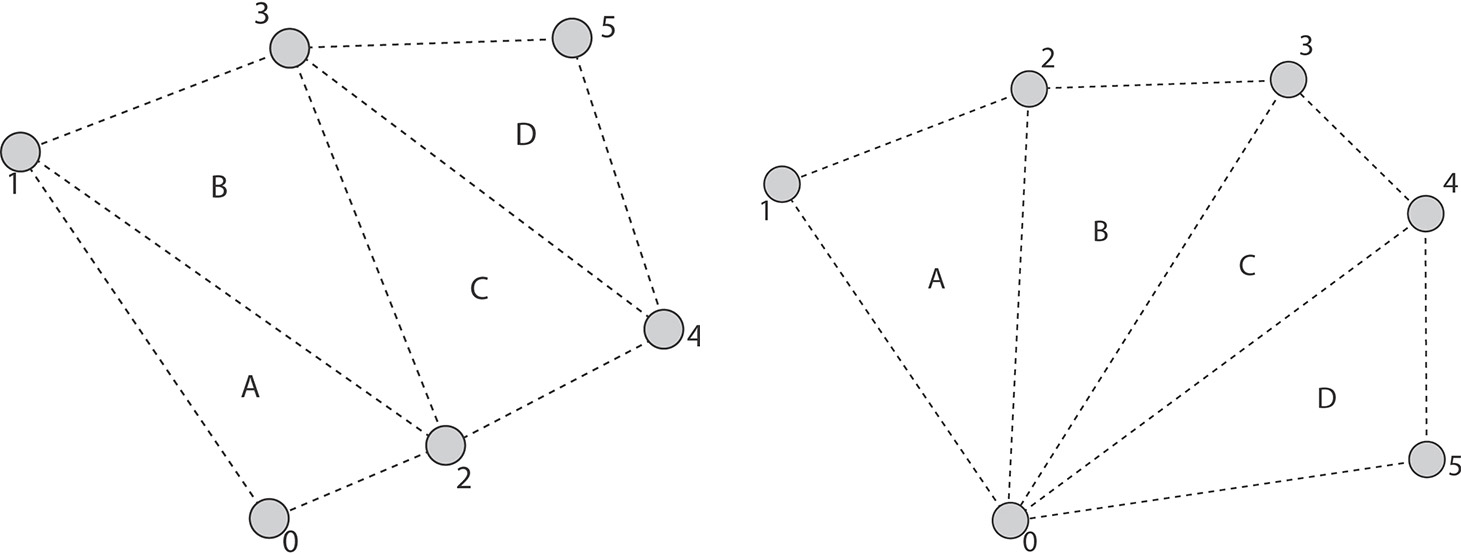
Next are the strip and fan primitives. These are groupings of vertices into primitives (lines or triangles) in which each line or triangle shares one or two vertices with the previous one. The strip and fan primitives are as follows:
• VK_PRIMITIVE_TOPOLOGY_LINE_STRIP: The first two vertices in a draw form a single line segment. Each new vertex after them forms a new line segment from the last processed vertex. The result is a connected sequence of lines.
• VK_PRIMITIVE_TOPOLOGY_TRIANGLE_STRIP: The first three vertices in a draw form a single triangle. Each subsequent vertex forms a new triangle along with the last two vertices. The result is a connected row of triangles, each sharing an edge with the last.
• VK_PRIMITIVE_TOPOLOGY_TRIANGLE_FAN: The first three vertices in a draw form a single triangle. Each subsequent vertex forms a new triangle along with the last vertex and the first vertex in the draw.
Strip and fan topologies are not complex but can be difficult to visualize if you are not familiar with them. Figure 7.2 shows these topologies laid out graphically.
Next are the adjacency primitives, which are typically used only when a geometry shader is enabled and are able to convey additional information about primitives next to them in an original mesh. The adjacency primitive topologies are
• VK_PRIMITIVE_TOPOLOGY_LINE_LIST_WITH_ADJACENCY: Every four vertices in the draw form a single primitive, with the center two vertices forming a line and the first and last vertex in each group of four being presented to the geometry shader, when present.
• VK_PRIMITIVE_TOPOLOGY_LINE_STRIP_WITH_ADJACENCY: The first four vertices in the draw form a single primitive, with the center two vertices forming a line segment and the first and last being presented to the geometry shader as adjacency information. Each subsequent vertex essentially slides this window of four vertices along by one, forming a new line segment and presenting the new vertex as adjacency information.
• VK_PRIMITIVE_TOPOLOGY_TRIANGLE_LIST_WITH_ADJACENCY: Similar to lines with adjacency, each group of six vertices is formed into a single primitive, with the first, third, and fifth in each group constructing a triangle and the second, fourth, and sixth being presented to the geometry shader as adjacency information.
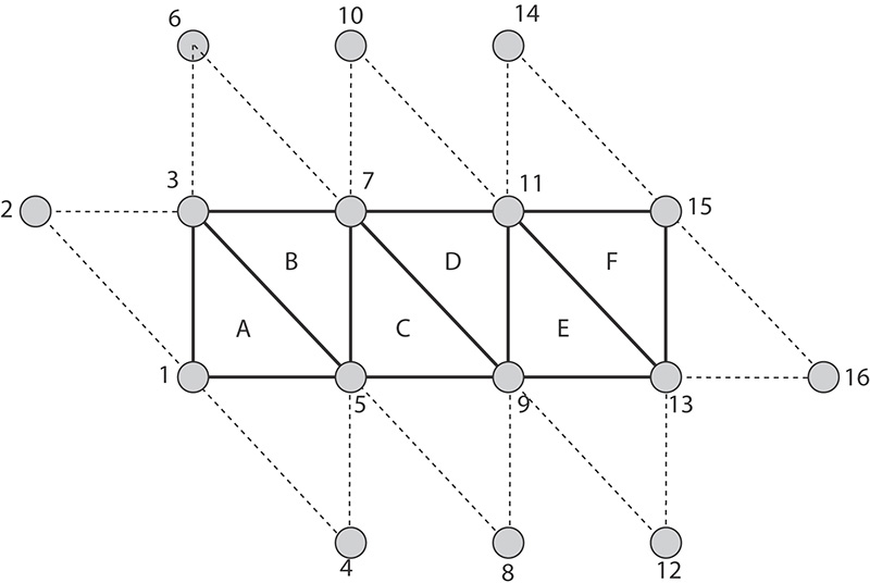
• VK_PRIMITIVE_TOPOLOGY_TRIANGLE_STRIP_WITH_ADJACENCY: This is perhaps the most confusing primitive topology and certainly needs a diagram to visualize. Essentially, the strip begins with the first six vertices forming a triangle with adjacency information as in the list case. For every two new vertices, a new triangle is formed, with the odd-numbered vertices forming the triangle and the even-numbered vertices providing adjacency information.
Again, adjacency topologies can be quite difficult to visualize—especially the VK_PRIMITIVE_TOPOLOGY_TRIANGLE_STRIP_WITH_ADJACENCY topology. Figure 7.3 illustrates the layout of vertices within the VK_PRIMITIVE_TOPOLOGY_TRIANGLE_LIST_WITH_ADJACENCY topology. In the figure you can see that there are two triangles formed from a total of 12 vertices. The vertices wrap around the outside of each triangle, with the odd-numbered vertices forming the center triangles (A and B) and the even-numbered vertices forming virtual triangles that are not rendered, but carry adjacency information. This concept carries on to the triangle strip
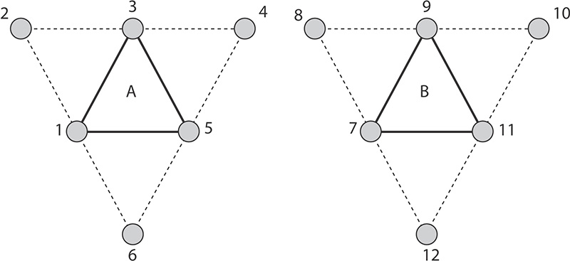
primitive. Figure 7.4 shows how it is applied to the VK_PRIMITIVE_TOPOLOGY_TRIANGLE_STRIP_WITH_ADJACENCY.
Adjacency topologies are typically used only when a geometry shader is present, as the geometry shader is the only stage that really sees the adjacency vertices. However, it’s possible to use adjacency primitives without a geometry shader; the adjacency vertices will simply be discarded.
The last primitive topology is VK_PRIMITIVE_TOPOLOGY_PATCH_LIST. This topology is used when tessellation is enabled, which requires additional information to be passed to pipeline construction.
The last field in VkPipelineInputAssemblyStateCreateInfo is primitiveRestartEnable. This is a flag that is used to allow strip and fan primitive topologies to be cut and restarted. Without this, each strip or fan would need to be a separate draw. When you use restarts, many strips or fans can be combined into a single draw. Restarts take effect only when indexed draws are used because the point at which to restart the strip is marked using a special, reserved value in the index buffer. This is covered in more detail in Chapter 8, “Drawing.”
Tessellation State
Tessellation is the process of breaking a large, complex primitive into a large number of smaller primitives approximating the original. Vulkan can tessellate a patch primitive into many smaller point, line, or triangle primitives prior to geometry shading and rasterization. Most of the state related to tessellation is configured using the tessellation control shader and tessellation evaluation shader. However, because these shading stages don’t run until vertex data has already been fetched and processed by the vertex shader, some information is needed up front to configure this stage of the pipeline.
This information is provided through an instance of the VkPipelineTessellationStateCreateInfo structure, pointed to by the pTessellationState member of VkGraphicsPipelineCreateInfo. The definition of VkPipelineTessellationStateCreateInfo is
typedef struct VkPipelineTessellationStateCreateInfo {
VkStructureType sType;
const void* pNext;
VkPipelineTessellationStateCreateFlags flags;
uint32_t patchControlPoints;
} VkPipelineTessellationStateCreateInfo;
When the topology field of the VkPipelineInputAssemblyStateCreateInfo structure is set to VK_PRIMITIVE_TOPOLOGY_PATCH_LIST, pTessellationState must be a pointer to a VkPipelineTessellationStateCreateInfo structure; otherwise, pTessellationState can be nullptr.
sType for VkPipelineTessellationStateCreateInfo is VK_STRUCTURE_TYPE_PIPELINE_TESSELLATION_STATE_CREATE_INFO. pNext should be set to nullptr, and flags is reserved for use in future versions of Vulkan and should be set to zero. The only field of significance in VkPipelineTessellationStateCreateInfo is patchControlPoints, which sets the number of control points that will be grouped into a single primitive (patch). Tessellation is a somewhat advanced topic and will be covered in more detail in Chapter 9, “Geometry Processing.”
Viewport State
Viewport transformation is the final coordinate transform in the Vulkan pipeline before rasterization occurs. It transforms vertices from normalized device coordinates into window coordinates. Multiple viewports can be in use simultaneously. The state of these viewports, including the number of active viewports and their parameters, is set through an instance of the VkPipelineViewportStateCreateInfo structure, the address of which is passed through the pViewportState member of VkGraphicsPipelineCreateInfo. The definition of VkPipelineViewportStateCreateInfo is
typedef struct VkPipelineViewportStateCreateInfo {
VkStructureType sType;
const void* pNext;
VkPipelineViewportStateCreateFlags flags;
uint32_t viewportCount;
const VkViewport* pViewports;
uint32_t scissorCount;
const VkRect2D* pScissors;
} VkPipelineViewportStateCreateInfo;
The sType field of VkPipelineViewportStateCreateInfo should be set to VK_STRUCTURE_TYPE_PIPELINE_VIEWPORT_STATE_CREATE_INFO, and pNext should be set to nullptr. The flags field is reserved for use in a future version of Vulkan and should be set to zero.
The number of viewports that will be available to the pipeline is set in viewportCount, and the dimensions of each viewport are passed in an array of VkViewport structures, the address of which is specified in pViewports. The definition of VkViewport is
typedef struct VkViewport {
float x;
float y;
float width;
float height;
float minDepth;
float maxDepth;
} VkViewport;
The VkPipelineViewportStateCreateInfo structure is also used to set the scissor rectangles for the pipeline. As with viewports, a single pipeline can define multiple scissor rectangles, and they are passed through an array of VkRect2D structures. The number of scissor rectangles is specified in scissorCount. Note that the index used for the viewport and scissor rectangles when drawing is the same, so you must set scissorCount to the same value as viewportCount. VkRect2D is a simple structure defining a rectangle in 2D and is used for many things in Vulkan. Its definition is
typedef struct VkRect2D {
VkOffset2D offset;
VkExtent2D extent;
} VkRect2D;
Support for multiple viewports is optional. When multiple viewports are supported, then at least 16 are available. The maximum number of viewports that can be enabled in a single graphics pipeline can be determined by inspecting the maxViewports member of the VkPhysicalDeviceLimits structure returned from a call to vkGetPhysicalDeviceProperties(). If multiple viewports are supported, then this limit will be at least 16. Otherwise, this field will contain the value 1.
More information about how the viewport transformation works and how to utilize multiple viewports in your application is given in Chapter 9, “Geometry Processing.” Further information about scissor testing is contained in Chapter 10, “Fragment Processing.” In order to simply render to the full framebuffer, disable the scissor test and create a single viewport with the same dimensions as the framebuffer’s color attachments.
Rasterization State
Rasterization is the fundamental process whereby primitives represented by vertices are turned into streams of fragments ready to be shaded by your fragment shader. The state of the rasterizer controls how this process occurs and is set using an instance of the VkPipelineRasterizationStateCreateInfo passed through the pRasterizationState member of VkGraphicsPipelineCreateInfo. The definition of VkPipelineRasterizationStateCreateInfo is
typedef struct VkPipelineRasterizationStateCreateInfo {
VkStructureType sType;
const void* pNext;
VkPipelineRasterizationStateCreateFlags flags;
VkBool32 depthClampEnable;
VkBool32 rasterizerDiscardEnable;
VkPolygonMode polygonMode;
VkCullModeFlags cullMode;
VkFrontFace frontFace;
VkBool32 depthBiasEnable;
float depthBiasConstantFactor;
float depthBiasClamp;
float depthBiasSlopeFactor;
float lineWidth;
} VkPipelineRasterizationStateCreateInfo;
The sType field of VkPipelineRasterizationStateCreateInfo should be set to VK_STRUCTURE_TYPE_PIPELINE_RASTERIZATION_STATE_CREATE_INFO and pNext should be set to nullptr. The flags field is reserved and should be set to zero.
The depthClampEnable field is used to turn depth clamping on or off. Depth clamping causes fragments that would have been clipped away by the near or far planes to instead be projected onto those planes and can be used to fill holes in geometry that would be caused by clipping.
rasterizerDiscardEnable is used to turn off rasterization altogether. When this flag is set, the rasterizer will not run, and no fragments will be produced.
The polygonMode field can be used to get Vulkan to turn triangles into points or lines automatically. The possible values for polygonMode are
• VK_POLYGON_MODE_FILL: This is the normal mode that is used to fill in triangles. Triangles will be drawn solid, and every point inside the triangle will create a fragment.
• VK_POLYGON_MODE_LINE: This mode turns the triangles into lines, with each edge of each triangle becoming a line. This is useful for drawing geometry in wireframe mode.
• VK_POLYGON_MODE_POINT: This mode simply draws each vertex as a point.
The advantage of using the polygon mode to turn geometry into wireframe or point clouds over simply drawing lines or points is that operations that operate only on complete triangles, such as back-face culling, are still performed. Thus, lines that would have encompassed a culled triangle are not drawn, whereas they would be if the geometry were simply drawn as lines.
Culling is controlled with cullMode, which can be zero or a bitwise combination of either of the following:
• VK_CULL_MODE_FRONT_BIT: Polygons (triangles) that are considered to face the viewer are discarded.
• VK_CULL_MODE_BACK_BIT: Polygons that are considered to face away from the viewer are discarded.
For convenience, Vulkan defines VK_CULL_MODE_FRONT_AND_BACK as the bitwise OR of both VK_CULL_MODE_FRONT_BIT and VK_CULL_MODE_BACK_BIT. Setting cullMode to this value will result in all triangles being dicarded. Note that culling doesn’t affect lines or points because they don’t have a facing direction.
Which direction a triangle is facing is determined from the winding order of its vertices—whether they proceed clockwise or counterclockwise in window space. Which of clockwise or counterclockwise is considered front-facing is determined by the frontFace field. This is a member of the VkFrontFace enumeration and can be either VK_FRONT_FACE_COUNTER_CLOCKWISE or VK_FRONT_FACE_CLOCKWISE.
The next four parameters—depthBiasEnable, depthBiasConstantFactor, depthBiasClamp, and depthBiasSlopeFactor—control the depth bias feature. This feature allows fragments to be offset in depth before the depth test and can be used to prevent depth fighting. This feature is discussed in some detail in Chapter 10, “Fragment Processing.”
Finally, lineWidth sets the width of line primitives, in pixels. This applies to all lines rasterized with the pipeline. This includes pipelines in which the primitive topology is one of the line primitives, the geometry or tessellation shaders turn the input primitives into lines, and the polygon mode (set by polygonMode) is VK_POLYGON_MODE_LINE. Note that some Vulkan implementations don’t support wide lines and will ignore this field. Others may run very slowly when this field is not 1.0; still others may honor this field completely and throw away all your lines if you set lineWidth to 0.0. Therefore, you should always set this field to 1.0 unless you’re sure you want something else.
Even when wide lines are supported, the maximum width of a line is device-dependent. It is guaranteed to be at least 8 pixels but could be much higher. To determine the maximum line width supported by a device, check the lineWidthRange field of its VkPhysicalDeviceLimits structure. This is an array of two floating-point values, the first being the minimum width of a line (which will be at most 1 pixel; its purpose is for drawing lines that are less than a pixel wide) and the second being the maximum width of a line. If variable line width is not supported, then both elements of the array will be 1.0.
Further, as line width is changed, a device may snap the width you specify into fixed-size increments. For example, it may support only whole-pixel size changes. This is the line width granularity, which can be determined by inspecting the lineWidthGranularity field of the VkPhysicalDeviceLimits structure.
Multisample State
Multisampling is the process of generating multiple samples for each pixel in an image. It is used to combat aliasing and can greatly improve image quality when used effectively. When you use multisampling, the color and depth-stencil attachments must be multisample images, and the multisample state of the pipeline should be set appropriately through the pMultisampleState member of VkGraphicsPipelineCreateInfo. This is a pointer to an instance of the VkPipelineMultisampleStateCreateInfo structure, the definition of which is
typedef struct VkPipelineMultisampleStateCreateInfo {
VkStructureType sType;
const void* pNext;
VkPipelineMultisampleStateCreateFlags flags;
VkSampleCountFlagBits rasterizationSamples;
VkBool32 sampleShadingEnable;
float minSampleShading;
const VkSampleMask* pSampleMask;
VkBool32 alphaToCoverageEnable;
VkBool32 alphaToOneEnable;
} VkPipelineMultisampleStateCreateInfo;
The sType field of VkPipelineMultisampleStateCreateInfo should be set to VK_STRUCTURE_TYPE_PIPELINE_MULTISAMPLE_STATE_CREATE_INFO and pNext should be set to nullptr. The flags field is reserved and should be set to zero.
Depth and Stencil State
The depth-stencil state controls how the depth and stencil tests are conducted and what happens to a fragment should it pass or fail either of those tests. The depth and stencil tests can be performed either before or after the fragment shader runs. By default, the tests occur after the fragment shader.1
1. Most implementations will only keep up the appearance that the depth and stencil tests are running after the fragment shader and, if possible, run the tests before running the shader to avoid running shader code when the test would fail.
To run the fragment shader before the depth test, we can apply the SPIR-V EarlyFragmentTests execution mode to the entry point of our fragment shader.
The depth-stencil state is configured through the pDepthStencilState member of VkGraphicsPipelineCreateInfo, which is a pointer to an instance of the VkPipelineDepthStencilStateCreateInfo structure. The definition of VkPipelineDepthStencilStateCreateInfo is
typedef struct VkPipelineDepthStencilStateCreateInfo {
VkStructureType sType;
const void* pNext;
VkPipelineDepthStencilStateCreateFlags flags;
VkBool32 depthTestEnable;
VkBool32 depthWriteEnable;
VkCompareOp depthCompareOp;
VkBool32 depthBoundsTestEnable;
VkBool32 stencilTestEnable;
VkStencilOpState front;
VkStencilOpState back;
float minDepthBounds;
float maxDepthBounds;
} VkPipelineDepthStencilStateCreateInfo;
The sType field for VkPipelineDepthStencilStateCreateInfo should be set to VK_STRUCTURE_TYPE_PIPELINE_DEPTH_STENCIL_CREATE_INFO and pNext should be set to nullptr. The flags field is reserved and should be set to zero.
The depth test is enabled if depthTestEnable is set to VK_TRUE. If the depth test is enabled, then the test to use is selected using depthCompareOp, which is one of the VkCompareOp enumerant values. The available depth testing operations are discussed in more detail in Chapter 10, “Fragment Processing.” If depthTestEnable is set to VK_FALSE, then the depth test is enabled. The value of depthCompareOp is enabled, and all fragments are considered to have passed the depth test. It should be noted, however, that when the depth test is disabled, no writes to the depth buffer occur.
If the depth test passes (or if the depth test is disabled), then the fragment passes on to the stencil test. The stencil test is enabled if the stencilTestEnable field of VkPipelineDepthStencilCreateInfo is set to VK_TRUE and disabled otherwise. When stencil testing is enabled, a separate state is provided for front- and back-facing primitives in the front and back members, respectively. If stencil test is disabled, all fragments are considered to have passed the stencil test.
The details of depth and stencil testing are covered in more depth in Chapter 10, “Fragment Processing.”
Color Blend State
The final stage in the Vulkan graphics pipeline is the color blend stage. This stage is responsible for writing fragments into the color attachments. In many cases, this is a simple operation that simply overwrites the existing content of the attachment with value(s) output from the fragment shader. However, the color blender is capable of mixing (blending) those values with the values already in the framebuffer and performing simple logical operations between the output of the fragment shader and the current content of the framebuffer.
The state of the color blender is specified using the pColorBlendState member of the VkGraphicsPipelineCreateInfo structure. This is a pointer to an instance of the VkPipelineColorBlendStateCreateInfo structure, the definition of which is
typedef struct VkPipelineColorBlendStateCreateInfo {
VkStructureType sType;
const void* pNext;
VkPipelineColorBlendStateCreateFlags flags;
VkBool32 logicOpEnable;
VkLogicOp logicOp;
uint32_t attachmentCount;
const VkPipelineColorBlendAttachmentState* pAttachments;
float blendConstants[4];
} VkPipelineColorBlendStateCreateInfo;
The sType field of VkPipelineColorBlendStateCreateInfo should be set to VK_STRUCTURE_TYPE_PIPELINE_COLOR_BLEND_STATE_CREATE_INFO, and pNext should be set to nullptr. The flags field is reserved for future use and should be set to zero.
The logicOpEnable field specifies whether to perform logical operations between the output of the fragment shader and the content of the color attachments. When logicOpEnable is VK_FALSE, then logical operations are disabled and values produced by the fragment shader are written into the color attachment unmodified. When logicOpEnable is VK_TRUE, logic operations are enabled for the attachments that support them. The logic operation to apply is the same for every attachment and is a member of the VkLogicOp numeration. The meaning of each of the enumerants and more information about logical operations is given in Chapter 10, “Fragment Processing.”
Each attachment can have a different format, and can support different blending operations. These are specified with an array of VkPipelineColorBlendAttachmentState structures, the address of which is passed through the pAttachments member of VkPipelineColorBlendStateCreateInfo. The number of attachments is set in attachmentCount. The definition of VkPipelineColorBlendAttachmentState is
typedef struct VkPipelineColorBlendAttachmentState {
VkBool32 blendEnable;
VkBlendFactor srcColorBlendFactor;
VkBlendFactor dstColorBlendFactor;
VkBlendOp colorBlendOp;
VkBlendFactor srcAlphaBlendFactor;
VkBlendFactor dstAlphaBlendFactor;
VkBlendOp alphaBlendOp;
VkColorComponentFlags colorWriteMask;
} VkPipelineColorBlendAttachmentState;
For each color attachment, the members of VkPipelineColorBlendAttachmentState control whether blending is enabled, what the source and destination factors are, what the blending operation is (for both the color and alpha channels separately), and which channels in the output image are to be updated.
If the colorBlendEnable field of VkPipelineColorBlendAttachmentState is VK_TRUE, then the remaining parameters control the state of blending. Blending will be covered in more detail in Chapter 10, “Fragment Processing.” When colorBlendEnable is VK_FALSE, the blending parameters in VkPipelineColorBlendAttachmentState are ignored, and blending is disabled for that attachment.
Regardless of the state of colorBlendEnable, the final field, colorWriteMask, controls which channels of the output image are written in this attachment. It is a bitfield made up of bits from the VkColorComponentFlagBits enumeration. The four channels, represented by VK_COLOR_COMPONENT_R_BIT, VK_COLOR_COMPONENT_G_BIT, VK_COLOR_COMPONENT_B_BIT, and VK_COLOR_COMPONENT_A_BIT, can be individually masked out for writing. If the flag corresponding to a particular channel is not included in colorWriteMask, then that channel will not be modified. Only the channels included in colorWriteMask will be updated through rendering to the attachment.
Dynamic State
As you have seen, the graphics pipeline object is large and complex, and contains a lot of state. In many graphics applications, it is often desirable to be able to change some states at a relatively high frequency. If every change in every state required that you created a new graphics pipeline object, then the number of objects your application would have to manage would quickly become very large.
To make fine-grained state changes more manageable, Vulkan provides the ability to mark particular parts of the graphics pipeline as dynamic, which means that they can be updated on the fly using commands directly inside the command buffer rather than using an object. Because this reduces the opportunity for Vulkan to optimize or absorb parts of state, it’s necessary to specify exactly what state you want to make dynamic. This is done through the pDynamicState member of the VkGraphicsPipelineCreateInfo structure, which is a pointer to an instance of the VkPipelineDynamicStateCreateInfo structure, the definition of which is
typedef struct VkPipelineDynamicStateCreateInfo {
VkStructureType sType;
const void* pNext;
VkPipelineDynamicStateCreateFlags flags;
uint32_t dynamicStateCount;
const VkDynamicState* pDynamicStates;
} VkPipelineDynamicStateCreateInfo;
The sType for VkPipelineDynamicStateCreateInfo should be set to VK_STRUCTURE_TYPE_PIPELINE_DYNAMIC_STATE_CREATE_INFO, and pNext should be set to nullptr. The flags field is reserved and should be set to zero.
The number of states that you wish to be dynamic is specified in dynamicStateCount. This is the length of the array pointed to by pDynamicStates, which is an array of elements from the VkDynamicState enumeration. Including a member of this enumeration in the pDynamicStates array tells Vulkan that you want to be able to change that state using the corresponding dynamic state setting commands. The members of VkDynamicState and their meanings are as follows:
• VK_DYNAMIC_STATE_VIEWPORT: The viewport rectangle is dynamic and will be updated using vkCmdSetViewport().
• VK_DYNAMIC_STATE_SCISSOR: The scissor rectangle is dynamic and will be updated using vkCmdSetScissor().
• VK_DYNAMIC_STATE_LINE_WIDTH: The line width is dynamic and will be updated using vkCmdSetLineWidth().
• VK_DYNAMIC_STATE_DEPTH_BIAS: The depth bias parameters are dynamic and will be updated using vkCmdSetDepthBias().
• VK_DYNAMIC_STATE_BLEND_CONSTANTS: The color blend constants are dynamic and will be updated using vkCmdSetBlendConstants().
• VK_DYNAMIC_STATE_DEPTH_BOUNDS: The depth bounds parameters are dynamic and will be updated using vkCmdSetDepthBounds().
• VK_DYNAMIC_STATE_STENCIL_COMPARE_MASK, VK_DYNAMIC_STATE_STENCIL_WRITE_MASK, and VK_DYNAMIC_STATE_STENCIL_REFERENCE: The corresponding stencil parameters are dynamic and will be updated using vkCmdSetStencilCompareMask(), vkCmdSetStencilWriteMask(), and vkCmdSetStencilReference(), respectively.
If a state is specified as being dynamic, then it becomes your responsibility to set that state when binding the pipeline. If the state is not marked as dynamic, then it is considered static and is set when the pipeline is bound. Binding a pipeline with static state makes the dynamic state undefined. The reason for this is that Vulkan implementations might optimize static states into the pipeline object and not actually program them into hardware if they’re not used or if it can otherwise be determined that this is valid. When a pipeline with that state marked dynamic is subsequently bound, it’s not defined whether the dynamic state is consistent in hardware.
When you are switching between pipelines that mark the same state as dynamic, however, then the state remains persistent across binds. Table 7.1 illustrates this.
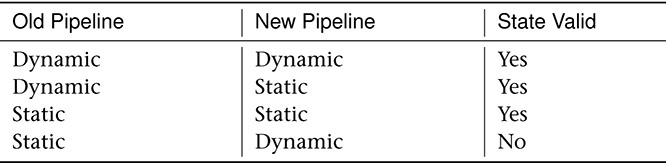
As you can see in Table 7.1, the only case in which state becomes undefined occurs when switching from a pipeline with that state marked as static to one in which the same state is marked as dynamic. In all other cases, the state is well defined and comes from either the pipeline’s state or the dynamic state set with the appropriate command.
If you set a dynamic state when a pipeline with that state set as static is currently bound, the results are undefined if you then draw with that pipeline. The effect could be to ignore the state-setting command and continue to use the static version of the state from the pipeline, honor the state-setting command and use the new dynamic state, or corrupt state altogether and break your application entirely. The effect will be different across implementations and will likely depend on which state is erroneously overridden.
Setting dynamic state and then binding a pipeline with that state marked as dynamic should cause the dynamic state to be used. However, it’s good practice to bind the pipeline first and then bind any related state simply to avert the possibility of undefined behavior.
Summary
This chapter provided a whirlwind tour of the Vulkan graphics pipeline. The pipeline consists of multiple stages, some of which are configurable but fixed-function, and some of which are made up of extremely powerful shaders. Building on the concept of the pipeline object introduced in Chapter 6, “Shaders and Pipelines,” the graphics pipeline object was introduced. This object includes a large amount of fixed function state. Although the pipelines built in this chapter were simple, a solid foundation was laid upon which to build more complex and expressive pipelines in later chapters.