
There was a great movie back in the 1980s that had a character giving his buddy tips on how to ski; his simple instructions were “Go that way, really fast. If something gets in your way, turn.” Well, that advice can apply to robots too. We want our robots to go toward the mission, and if an obstacle gets in the way, we’re going to need to turn the robot. The trick is turning in a consistent manner that allows the robot to end up where we expect it to.
There are just as many factors that affect a smooth turn as for going straight. Your robot’s wheels, chassis design, and, of course, programming all play a big part in turning smoothly.
Tip
When going straight, having a robot that has a low center of gravity is helpful. The same is true when turning. If the robot chassis is top heavy or off balance, a quick turn could cause the robot to flip over on its side. Even a robot that tilts a little due to loss of balance when turning would cause undesired turning accuracy. If the drive wheels lose contact with the field at any time during a turn, making an accurate turn will be impossible. You want consistent and accurate turns, so keep the robot on the ground at all times. Keep the chassis balanced and turn slowly to avoid losing wheel contact.
Turning Designs
There are basically two types of turning method designs used on LEGO robots, and really only one of them is desirable when building a FIRST LEGO League robot. There are differential steering drive systems and steering drive systems. The latter is rarely used in FIRST LEGO League robots because it’s too complex and difficult to pull off with a LEGO MINDSTORMS robot. I do think steering system robots have their place and are a great challenge to build, but when it comes to building a winning FIRST LEGO League robot, the differential steering system is hard to beat for its simplicity and ease of use.
Differential Steering Systems
A differential steering robot, also called a differentially steered drive system, is one of the most common steering systems used on small robots and works well for LEGO robots. Differential steering is very simple and easy to create with LEGO, and it works much like the drive system of a wheelchair. Each axle is independently controlled for driving and steering, thus allowing the axles to move at different speeds and directions. This allows the robot to turn based solely on applying varying power to the motors. So, like a wheelchair, if you turn one wheel forward and one in reverse, the chair will spin in place (assuming you turn both wheels at the same rate and degrees of rotation). Also if you spin only one wheel, the chair will rotate in a circle using the stationary wheel as the pivot point. And if you turn both wheels in the same direction but at different speeds, the chair will turn in a curved path toward the slower wheel. Being able to turn in such a way allows a robot to make quick steering changes with a minimum of space. The DemoBot (see Figure 4-1) uses differential steering for making turns.
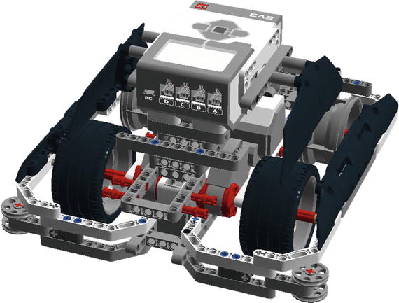
Figure 4-1. DemoBot is an example o f a differental steering robot chassis design. The two motors are used to control the speed as well as the direction.
If you notice on the DemoBot, the rear wheels do not have tires, because when the front tires are rotating and making the robot turn, the rear wheels are going to skid across the surface. The rear wheels do not need to get traction; they are simply there to help balance the robot. If the robot was using a caster wheel on the back, that wheel would simply turn passively with the robot as it rotated. You can even have skids on the back, as I discussed in Chapter 2. Whatever design you use, make sure it does not create a lot of friction when the robot starts to turn. The trick is to make the turn as frictionless as possible, so that you get a nice smooth turn. If the robot stumbles or encounters too much friction with the field, the turning accuracy will be diminished considerably.
Be careful not to confuse differential steering with the differential drive system used on automobiles; a differential drive system is where a single source of power is delivered to the drive wheels through a differential gear system. This is not the same as having two independent power sources for the robot’s drive wheels. Sometimes similar terminology can confuse people.
Steering Drive Systems
A steering drive system is what most cars use to turn; in a robot, you would have a single motor powering the robot and then a second motor controlling the steering. You would most likely have a differential gear system on the drive wheels to prevent skidding and some kind of rack system on the front steering mechanism. With LEGO robots, systems like this can be a bit more difficult to build but can be done with a little patience.
There are multiple variations for a steering drive robot. You can have two wheels that turn, like on a car, or have a single steering wheel that controls the steering. When having two wheels that steer, you have to be concerned about wheel skid, since both steering wheels are pivoting on their own pivot points and not on a common point. Cars overcome this problem by using Ackerman steering correction. This is a geometry that reduces the skid of the wheels by forcing the steering wheels to turn along the same steering arc. Without Ackerman correction, the steering wheels will turn on different steering arcs, forcing them to skid and throw off your robot’s odometry calculations. A single steering wheel such as on a tricycle will prevent this problem, since you then only have to deal with a single turning arc instead of two.
The advantage to a steering drive system is that you have separated the drive system from the steering system, so you no longer have to worry about issues like motor matching and keeping two motors’ rotations in sync. This is great for situations in which you’re using odometry.
A disadvantage to using a steering drive is that turning into tight spots is not as easy as it is with a differential steering system. A differential steering system has a zero turning radius, while a steering drive robot must move some distance as it turns. As with a car, you can turn the steer wheels all you want, but a robot with a steering drive system won’t actually start to turn until it moves either forward or backward. You’ll see many lawn tractors that now use a zero turn radius system so they can get into tight spots when mowing a lawn, versus a traditional lawn tractor that might have to back up and make multiple attempts to reach a hard-to-access patch of grass.
One of the biggest disadvantages that I have found with steering drive robots is that when a robot is running in autonomous mode, such as FIRST LEGO League robots, it’s very hard to keep track of when the robot is pointed straight. Even with the built-in rotation sensors in the EV3 servos, you still can never be 100 percent certain that the robot’s steering is tracking straight. If the robot is remote controlled, it’s easy for the human operator to adjust the steering back to straight, but it’s a much larger task with autonomous LEGO robots. I have never seen any real benefits of going with such a design in a LEGO robots competition such as FIRST LEGO League.
Calculating Turns
There are two different ways to turn a differential steering robot: by turning both wheels or by only turning one wheel and pivoting on the stationary wheel. The trick is to figure out how much you should turn the wheel to get the desired turning position.
Bear in mind that, while you can accurately calculate the proper degrees needed for a precision turn, you are still dealing with LEGO robots that are not precision machines. No matter how accurate your math, any LEGO robot that you build will still need some final tweaking.
Note
There are about six to eight degrees of gear slack in a LEGO EV3 large servo, so getting accurate movements down within a few degrees will not be possible. Always allow some room for error when turning.
Single-Wheel Turns
In a single-wheel turn, one wheel remains stationary while the other moves and controls the turn. If you are turning your robot to the left by only turning the right wheel forward and keeping the left wheel stationary, this will create a steering circle with the left wheel position as the center (pivot point), and the distance between the right and left wheel, called the track, will be the radius of the steering circle, as shown in Figure 4-2. The circumference of the steering circle is calculated with the following formula:

Figure 4-2. DemoBot making a 180-degree turn with a single motor would create a steering circle with the diameter being twice that of the robot’s track. The track is the distance between the robot’s drive wheels. The center of the steering circle would be the point at which the robot would pivot on the nonmoving wheel.
Circumference = 2 × radius × piTo turn 90 degrees, the robot would have to travel one-fourth of the circumference of the steering circle, while a 180-degree turn would require traveling half the steering circle circumference. Therefore, to calculate the desired duration needed in the motor block, you would first figure out the distance you need to travel around the steering circle. If you’re turning 360 degrees (a complete circle) with the DemoBot, which has a track of 5.5 inches, the equation would be something like this:
Distance = Steering circle × circumferenceDistance = 2 × 5.5 × 3.14Distance = 34.54 inches
With the distance now known, you can calculate the duration needed in the motor block by using the same formula that you used to calculate the duration when going straight. The robot has wheels that have a diameter of 2.71 inches, so the calculation will look like this:
Duration = Distance / Wheel circumferenceDuration = 34.54 / (2.71 × 3.14)Duration = 4 rotations
The value 2.86 gives you the rotation duration needed to turn the robot a single degree; for the robot to make a complete circle, you would multiply 360 by the single degree number (2.86):
Duration = 4 rotations × 360 degreesDuration = 1440 degrees
Now you have found that the number 4 is the key. You can multiply this number by any angle turn you want the robot to make. If you want the robot to turn 90 degrees instead of 360, you simply calculate the duration by using the newfound key of 4. The duration for a 90-degree turn is figured like such:
Duration = 4 × 90Duration = 360 degrees
Even though the key value is unitless, remember when making these calculations that you keep the units the same for your other values, so if you’re measuring your track in inches, the resulting distance will also be in inches. This is the same for the wheel diameter; if all your other measurements are in inches, you need to measure the wheel in inches as well. Mixing English measurements with metric measurements can cause disastrous results.
Note
One of the most famous of all metric versus English mixups resulted in the loss of the Mars Climate Orbiter that was part of NASA’s Mars Surveyor ’98 program. That spacecraft was destroyed due to a navigation error induced by using metric values where English values (that is, Imperial System, or IS, values) were expected. You can read more about the story at http://en.wikipedia.org/wiki/Mars_Climate_Orbiter .
Dual-Wheel Pivot
With the single-wheel turn, your robot is only powering one wheel and turns the robot around an arc. But if you turn both wheels in opposite directions, you can pivot the robot right where it is sitting. The pivot point is no longer the stationary wheel but the center of the robot’s track. You can even calculate the number of degrees needed to make the turn in the same way you did with the single-wheel turn. The only difference is that you will have to divide the degrees in half and apply them to both wheels; and remember that one wheel will be going in the opposite direction of the other. Figure 4-3 shows that the steering circle is much smaller than the steering circle of a single-wheel turn, actually half the size.

Figure 4-3. DemoBot making a 180-degree dual-wheel pivot turn with both motors would create a steering circle with the diameter equal to the length of the robot’s track. The center of the steering cirlce would be the center point of the robot track.
Say you want to pivot the DemoBot 180 degrees. You would again use the key value of 4 that was calculated earlier. This time, you would multiply it by 180 and then divide by 2:
Pivot duration = (4 × 180) / 2Pivot duration = 720 / 2Pivot duration = 360 degrees
If you are using a Move Steering block, you would set the steering to 100 or –100, depending on which direction you wanted to turn, and then enter a duration of 360 degrees, as shown in Figure 4-4.

Figure 4-4. A Move Steering block being set to pivot the DemoBot 180 degrees by using the value of 360 as the degrees and the steering set to the far right
You can also use a Move Tank block. Simply set the duration to 360 degrees and set one motor to travel in the opposite direction of the other (see Figure 4-5).

Figure 4-5. The Move Tank block being set to pivot the DemoBot 180 degrees by using the value of 360 as the degrees and setting the two motors in opposite directions
Both the Move Steering and Move T ank blocks work equally well for pivoting. I always preferred the pairing of the two motors in the Move Tank block. However, that is just my personal preference.
Programming
I’ve already mentioned that you can choose between Move Steering and Move Tank blocks when turning. You can also create custom blocks using the My Block builder. The following subsections show how to program these different choices.
Move Steering Block
I mentioned earlier in Chapter 3 that the Move Steering block would be use when you wanted a robot to go straight. Now that you want the robot to turn, the Move Steering block can be used again. The Move Steering block has a steering parameter that allows for values between –100 and 100. A slider on the block can move 100 positions to the right and 100 positions to the left.
The key values that are helpful with using the Move block for steering are provided in Table 4-1.
Table 4-1. Move Steering Block Common Steering Settings
Steering Value | Steering Results |
|---|---|
100 | Pivot to the right |
50 | Turn to the right using one motor |
0 | Go straight |
–50 | Turn to the left using one motor |
–100 | Pivot to the left |
Other steering values are allowed and can be useful when you want to travel in a large arc, but these require a bit more trial and error when using the Move Steering block. It is a good idea to keep the speed in the 25–75 range; going too fast or too slow adds some unexpected results to the Move Steering block at times.
Move Tank Block
I have always preferred to have my teams use the Move Tank block when making turns. The results can be much more predictable because you are controlling each motor separately; you have the ability to get a bit more precision with the values that you can apply to the motors. Using a Move Tank block lets you apply different power values; this can be helpful when trying to match a particular trajectory arc. At the same time, teams new to EV3 sometimes get confused by switching between Move Steering and Move Tank blocks. If you’re more comfortable with using just the Move Steering block, do what works best for you and your team.
With the Move Tank block, you will find that you have more control over your turns simply because you specify the actual power for each motor. As you saw earlier when calculating the durations for various types of turns, it’s nice to have this kind of control over each motor.
If I were trying to move my robot along a large trajectory using arcs, the Move Tank block would give me the ability to navigate such an arc with a lot more predictability.
Creating a Custom MyPivot Block
As you learned in Chapter 3, you can create your own custom programming blocks in EV3 by using My Block components, which allow you to take some of your own code and combine it i nto a usable block of code that you can share among many different programs. Code reusability is great for saving time and memory in the EV3 brick. Also, including custom My Block components in your code is one of the things that technical judges will be looking for during any kind of technical interview with your team. Be sure to talk about any custom blocks you create and make sure everyone on the team understands what they do.
While doing all the calculations for figuring out the correct duration needed to turn the robot in the direction you desire, you may have realized that much of that logic could be included in a custom My Block to be used for making a pivot turn; let’s call that new block MyPivot.
For example, once you know the key value, 4 for the DemoBot, you could make that a constant in your new MyPivot block. Then, all you would need to do is enter the desired turning degrees and let the block calculate the true duration needed for your robot to complete the turn.
If your robot’s wheels or track size change in the future, you would simply recalculate the key value and modify the key constant in your MyPivot block without needing to modify any of the code elsewhere. In Figure 4-6, you can see the code that will make up the DemoBot’s new MyPivot block. There is a Variable block for the degrees and a Constant block that will hold the key value of 4. These values are then passed to the Math block, where they are multiplied by each other and passed to one more Math block so that it can divide them by 2. The new calculated duration is then passed to a Move Tank block that has its motors running in opposite directions.

Figure 4-6. The definition of MyPivot blo ck, which will allow the robot to pass in the desired turn degrees and have the duration calculated automatically
Now, to create the new MyPivot block, you will select all the blocks in your code except the Degrees variable; let’s purposely leave this block out of the selection (you’ll see why in a moment). Once the blocks are selected, as shown in Figure 4-7, go to the Edit menu and select Make a New My Block. Then you will see the My Block Builder dialog box with the code you selected displayed. Notice that, since you did not select the Variable block that contained the degrees value, a special parameter wire was added to the new block. Figure 4-8 shows the newly created MyPivot block being used with the single parameter of Degrees.
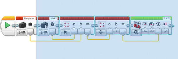
Figure 4-7. Selected blocks that will be a part of the new MyPivot block

Figure 4-8. The My Block Builder with the code blocks for the MyPivot block. The Degrees input will be defined in the Parameter Setup tab.
Now, when you’re finished in the My Block Builder dialog, the newly created MyPivot block will be inserted into the code and put in place of the code you selected to be p art of the block, as shown in Figure 4-9. You’ll also notice that, when you select the MyPivot block, you are presented with one single parameter labeled Degrees, as you defined in the Parameter Tab when creating the new block. This parameter is the amount of degrees you want the robot to pivot.

Figure 4-9. The new MyPivot block is connected to the Variable block that was left out of the MyPivot definition.
If you double-click the new MyPivot block, you’ll see that the application will open the block code in a new tab so that you can modify the code if needed. Also you will notice the Degrees parameter with its own wired block, as shown in Figure 4-10.

Figure 4-10. Expanded MyPivot block
Creating a Custom MyTurn Block
Say you want a block to do single-wheel turns. You can simply modify the MyPivot block by removing one of the Motor blocks and removing the Math block that was dividing the calculated value by 2. The results would look like those shown in Figure 4-11.

Figure 4-11. The MyTurn block , simliar to the MyPivot block but with only one Motor block and a single Math block
Gyro Sensor
One of the additions included with the EV3 is a new sensor, the Gyro Sensor. This allows the measurement of angles; actually it doesn’t measure angles but rather angle velocity. This means it can measure the speed at which the robot it changing angles and tries to track the angle. The accuracy is plus or minus four degrees per 90 degrees.
If accuracy is critical for your robot’s turn, then the Gyro Sensor might not be your best choice. Here I will discuss a few tricks to help you improve the accuracy of the Gyro Sensor.
Calibrating the Gyro Sensor
There is no built-in Gyro Sensor calibration block for the EV3, but you can take advantage of the fact that the Gyro Sensor resets anytime you change the mode, so changing from Rate to Angle will cause the recalibration. When doing this calibration, it is important that the robot be perfectly still in order for the calibration to work correctly. The program in Figure 4-12 shows a simple calibration program.

Figure 4-12. Custom Gyro Sensor calibration code block
Using the Gyro Sensor to Make a Turn
If you simply rely on the v alues of the Gyro Sensor when making turns, you will notice that it experiences a lot of lag time in getting the readings. So when the Gyro Sensor reaches the desired angle, there is sometimes a delay or lag in getting that value to the code, causing the robot to turn farther than desired.
One way to help compensate for the lag time is to design your program so that the robot slows down as it gets closer to its desired angle. The program in Figure 4-13 shows how to do this with the help of a Math block. The angle value from the Gyro Sensor is subtracted from the desired angle, 90 degrees in this case, and the sum of the subtraction is used as the power given to the motors in the Steering block. The power value will decrease as the Gyro Sensor angle value increases. The slowing down of the motors will allow the values to be more accurately read the closer you get to the desired angle value. The Loop block will exit once Motor B’s power value gets to zero, so it will exit the loop once the motors have stopped.
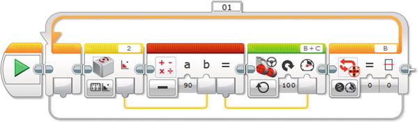
Figure 4-13. Turning code slowing the motor power down as the value gets closer t o 90-degree angle
Mounting the Gyro Sensor on Your Robot
The Gyro Sensor needs to be m ounted on the robot so that it’s level with the ground when the robot is sitting still. Also it’s recommend that the sensor be kept away from any of your robot’s motors. The moving motors can cause some inference with the Gyro Sensor’s performance. Figure 4-14 shows an easy mounting location on the DemoBot is the side of the EV3.
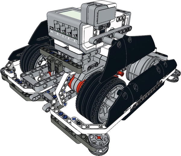
Figure 4-14. DemoBot with a Gyro Sensor mounted to the side of the EV3
Summary
Steering a LEGO robot can at times be an art, but knowing the math behind accurate turning can help get your robot close to the place you want it to go. I would never make more than two turns before realigning the robot with some fixture on the game field; I’ll discuss how to do this in later chapters. Too many unchecked turns in a single run can cause the room for error to expand greatly.
When making a turn with your robot, think it through, and try not to guess at the duration and angle needed. The more you can understand about why your robot is turning the way that it is, the easier it will be for you to make corrections in its turning direction.