
Chapter 3. Rotoscoping, Motion Tracking, and 2D Matchmoving
In addition to selections, extractions, cloning, and compositing, the other three most important skills in a visual effects artist’s arsenal—which you will need to understand and become proficient with—are rotoscoping, motion tracking, and matchmoving. Rotoscoping allows us to very accurately modify frames of a sequence or animation on a frame-by-frame-accurate basis. By motion tracking footage, we can precisely follow the motion of a subject in frame, or the sequence as a whole, and then do a wide variety of things with the tracking data we obtain—everything from attaching a 2D or 3D object and stabilizing and destabilizing the image, to semi-automating our roto, paint, or cloning work.
Introducing Roto
Perhaps one of the most important and most misunderstood terms in VFX is the term rotoscoping, or, more commonly these days, roto for short. The term is derived from the old days of cel animation in which artists who wanted to create lifelike motion in their animated characters would use a machine called a rotoscope, which projected filmed images onto the animator’s animation plate (yes, the same plate we derive our VFX terms from, such as background plate, foreground plate, clean plate, and so on). The animator would then trace, draw, or paint over the image onto a glass or acetate animation cel (celluloid made of cellulose nitrate and later cellulose acetate). This process became known as rotoscoping. The job of painting frame-by-frame became rotopaint.
As the use of computers emerged onto the animation and VFX scene, it became more efficient to create a shape frame-by-frame on a computer screen and simply move the shape, rather than repainting it every frame as had been previously done. To make things even more efficient, the use of spline-based tools to create shapes quickly became the state of the art because splines (which are mathematically created) could, additionally, be modified periodically (or keyframed) and the computer would automatically create (interpolate) the in-between or tween shapes. The job of rotopaint quickly gave way to the new form, rotosplining (rotoscoping using splines, which interpolate between keyframes).
Rotoscoping has since become synonymous with anything that is done on a frame-by-frame basis, from the hand painting of mattes to clay and stop motion animation. All of these have come to be known collectively as roto.
Rotoscoping Mattes
One of the most basic uses of roto is in the creation of mattes. As you saw in Chapter 2, to most efficiently perform key color extractions for compositing, it is critical that we use garbage and core mattes to allow us to retain as much detail as possible in the fine edges of our image. Because our image is likely moving, rotosplines will be the tool of choice to create our mattes. When rotoing, you will be able to move entire rotospline shapes and combine them into the final matte instead of having to paint entire mattes by hand every frame, which is very tedious and time consuming. The computer helps you by drawing all of the frames in between (or tween) your keyframes. You draw a frame of your rotospline, set a keyframe, move the timeline to another position, and set a new keyframe, and the software creates and animates all the tween frames.
There is much disinformation as to the strategies for placing keyframes while doing roto work—continually halving the number of frames, placing keyframes at each halfway mark, placing keyframes every ten frames, placing keyframes every x number of frames, and so on. All of these are poor, inaccurate, and wasteful strategies for doing roto and will usually create far too many keyframes, resulting in much more work than is necessary, as well as poor matte motion.
Note
Roto work is still a very patience-intensive job. A good way to approach roto is to get into the proper mindset for the task. You will be spending a lot of time doing very repetitive and detailed work, so being in a rushed or impatient mood will no doubt result in frustration. Get relaxed, pour a cup of coffee or tea, perhaps (for some people) put on some relaxing music you enjoy. Roto is much more enjoyable if you can get into a groove or “flow” (the Zen-like state of relaxed free-flowing concentration).
Roto Basics: Types of Rotosplines
To get started with a roto project, you first need to decide which is the best type of rotospline to use for the particular task at hand. The two most common types of rotosplines used for roto work are the Bezier curve and the B-spline curve.
Bezier
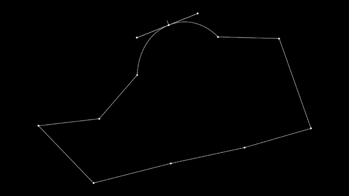
Bezier (pronounced bez-ee-ay) curves are parametric curves created by placing points, or vertices, which are then automatically connected by rubber-band–like line sections. Simply placing points will give you sharp-pointed, or cusp, corners, like those you see in Figure 3.1, whereas clicking and then dragging the mouse will pull out two tangent handles from the point that can be controlled together and used to form a smooth curve, like the top point in Figure 3.2.
Figure 3.1. Sharp-edged, or cusp, Bezier curve

Figure 3.2. Tangent handles pulled out to create a smooth curve
These tangent handles can also be broken and controlled individually to create sharp or obtuse angles and curves, as seen in Figure 3.3.
Figure 3.3. Tangent handle broken to create sharp or obtuse angles

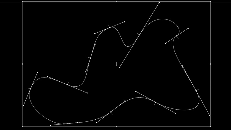
Because Bezier curves are parametric, their vertices can easily be converted back and forth from curves to cusped, and tangent handles can be animated or modified at any time, as seen in Figure 3.4.
Figure 3.4. All vertices converted to smooth
B-Spline
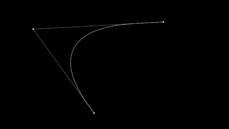
B-spline curves, unlike Bezier curves, require three points, or vertices, to create a curve. A B-spline uses these three points to interpolate a smooth curve between them as you can see in Figure 3.5.
Figure 3.5. B-spline curve interpolated between 3 points
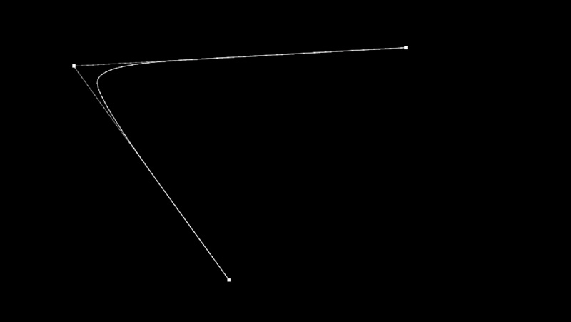
Although B-spline curves don’t have the tangent handle controls that Bezier curves have, they can be more accurately controlled by adjusting the weight or tension of each vertex. You can think of this weight/tension as being like gravity. The stronger the weight or tension is, the stronger the pull of gravity on the curve toward the vertex, as shown in Figure 3.6.
Figure 3.6. Center point weight/tension increased to create sharper curve
Deciding Which Type of Curve to Use
Each type of curve has its advantages. For rotosplining hard surfaces with straight edges, Bezier curves are much faster because they are straight by default until the tangent handles are pulled out from a point. I prefer the workflow for using them for most everything, since once you get the hang of them, creating almost any shape or following virtually any edge is fast and intuitive.
On the other hand, many artists prefer B-splines and feel they are faster using a “put the points down quickly and come back to refine them after” workflow. B-splines are particularly good for rotoing organic shapes because they are always perfectly smooth by default. You can think of the two different types of splines as almost opposite workflows, Bezier splines are sharp edged by default, but you can make them smooth, and B-splines are smooth by default but you can make them sharp edged.
Advanced Spline Features
Although rotosplines are great at creating sharp and smooth curves, the principles we discussed in Chapter 2 should instantly come to mind. Almost nothing in reality has a perfectly sharp edge. Fortunately, most high-end applications have solutions for this exact challenge. First, and simplest, is the same technique we used in Chapter 2—a feather or blur. Most professional applications provide for not only an edge feather/blur control but for various types of falloff as well. In addition, the best roto apps provide a double-edged rotospline, which allows for a second, and attached set of curves to be pulled from the first, allowing for very precise feathered edges that can be custom tailored to your subject to account for varying amounts of motion or blur, as seen in Figure 3.7.
Figure 3.7. A double-edged rotospline showing varying amounts of edge feathering
The Golden Rules of Roto
When rotoing, a definite set of Golden Rules should be followed to ensure the best and cleanest possible matte with the least amount of edge vibration or chatter. Engrain these Golden Rules in your memory; they are critical to good roto work:
1. Create your shapes with as few points possible (the more points you have to deal with, the greater the chance of matte chatter).
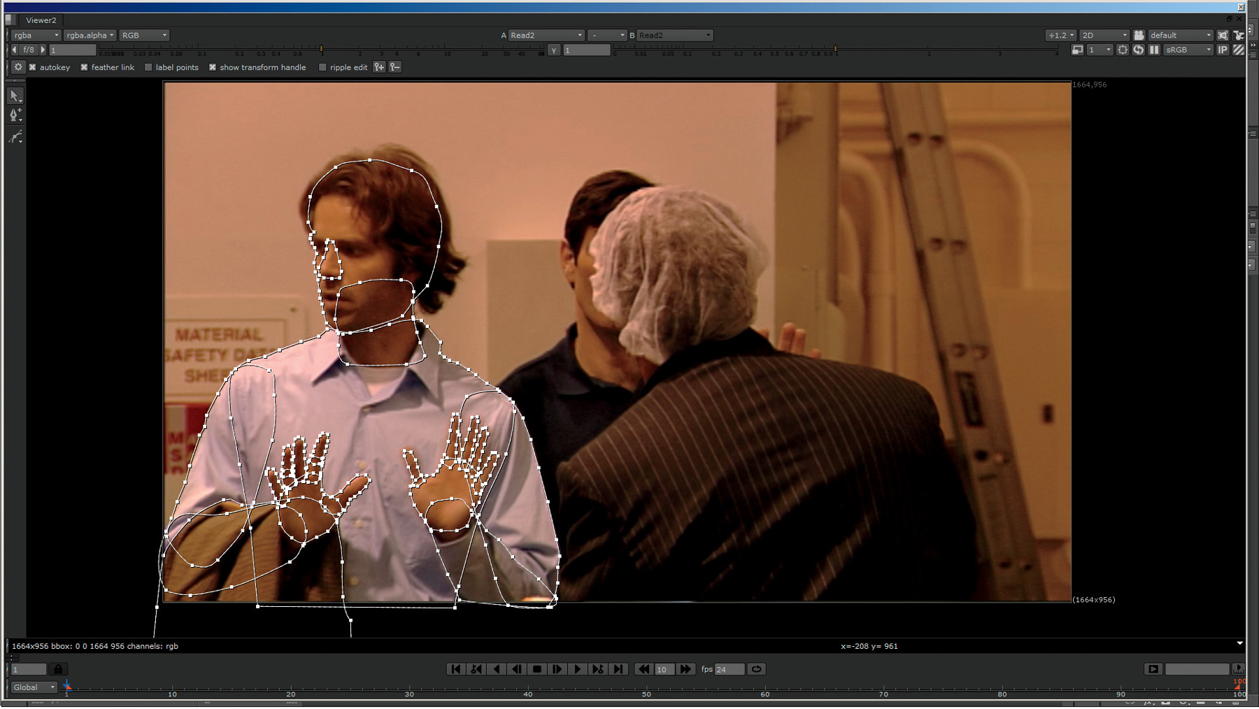
2. Create your mattes using multiple individual roto shapes for every part of the subject that will move or change shape in profile within the sequence (although you may be tempted to create your mattes using one big roto shape, as in Figure 3.8, this will very likely end in disaster as soon as a part of the subject disappears into the body of the shape and reappears out the other side, as when an actor turns from side to side.) Creating your mattes using multiple individual animated shapes for each moving part (as seen in Figure 3.9) allows for whole shapes to be moved without individual points needing to be manipulated, thus reducing matte chatter.
Figure 3.8. Bad roto—do not use one big shape like this.
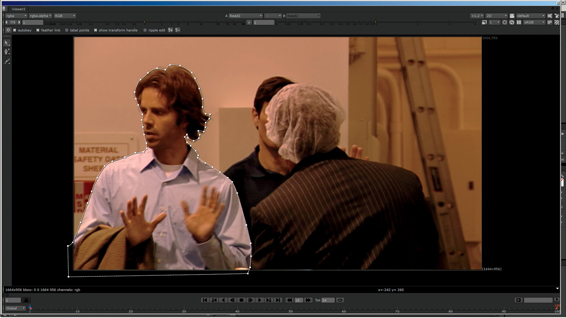
Figure 3.9. Good roto—proper break up of shapes into small shapes that can be articulated as a whole
3. Think of creating a “paper puppet” when rotosplining people or subjects with moving parts; create rigid shapes for each part that doesn’t change shape (i.e., for a person, you’d create a shape for the upper arm, connect it to a shape for the lower arm, connected to a shape for the hand, fingers, and so on). This allows for the simple rigid animation—via translation, rotation, and scale—of entire shapes without having to do extensive single point adjustments.
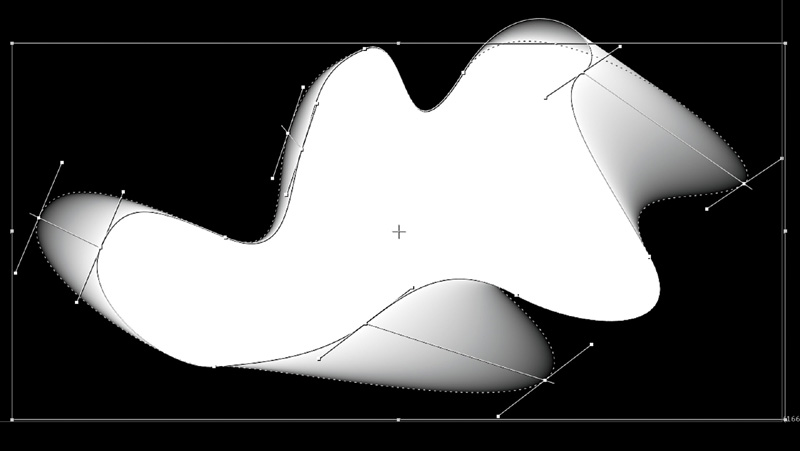
4. When animating shapes, find the frame where the subject moves farthest away from the rotoshape’s position before either changing direction or moving back toward the original position. That is the point at which you want to place your keyframe. (in Figure 3.10, we see actor Chad Ayers at the forward most position in frame 1; by frame 50, he is at the farthest point back; and he has moved forward again toward his beginning position at frame 100. Frame 50, his farthest point, is where we will place the first keyframe. After this, we find the next farthest point he moves to before either changing direction or starting to move back toward this position, and place our keyframe at this frame. We continue this process until the spline is locked to the motion).
Figure 3.10. Best frame at which to place a roto keyframe

5. The object is to set as few keyframes as possible. This will deliver the cleanest and smoothest animation possible.
6. It is perfectly correct and common to start from the beginning and work forward, start at the end and work backward, start in the middle and work forward, then backward, and so on. Many times you will have to work in small segments as well.
7. When moving rotoshapes, your first line of defense is to try to move all, or as many of the shapes as possible, together by translating, scaling, and rotating them as a single unit.
8. If this isn’t possible, try to move as many individual whole shapes as possible by translating, scaling, and rotating them as a single units.
9. If this isn’t possible, try to move as many points together as possible by translating, scaling, and rotating them as a single unit.
10. Only as a last resort after all of the above are exhausted should you move individual points in a spline.
Note
These procedures are critical to good roto work; they are not just suggestions!
Isolated Roto for Keying
In addition to utilizing rotosplines to create mattes for extractions, you can use rotosplines to isolate areas of an image that are particularly difficult to extract for one reason or another. In Figure 3.11 you can see the matte created from the combined splines seen in Figure 3.9. Notice how it would be extremely difficult to create a matte of the actor’s hair using this method; you’d be trying to create individual shapes for each hair or set of hairs. For this, you can use an isolated roto matte, like the one in Figure 3.12, just to isolate and then key a specific feature—in this case the hair; you’d then combine the matte created with that key with the ones you created previously using rotosplines.
Figure 3.11. Matte created from rotosplines in Figure 3.9
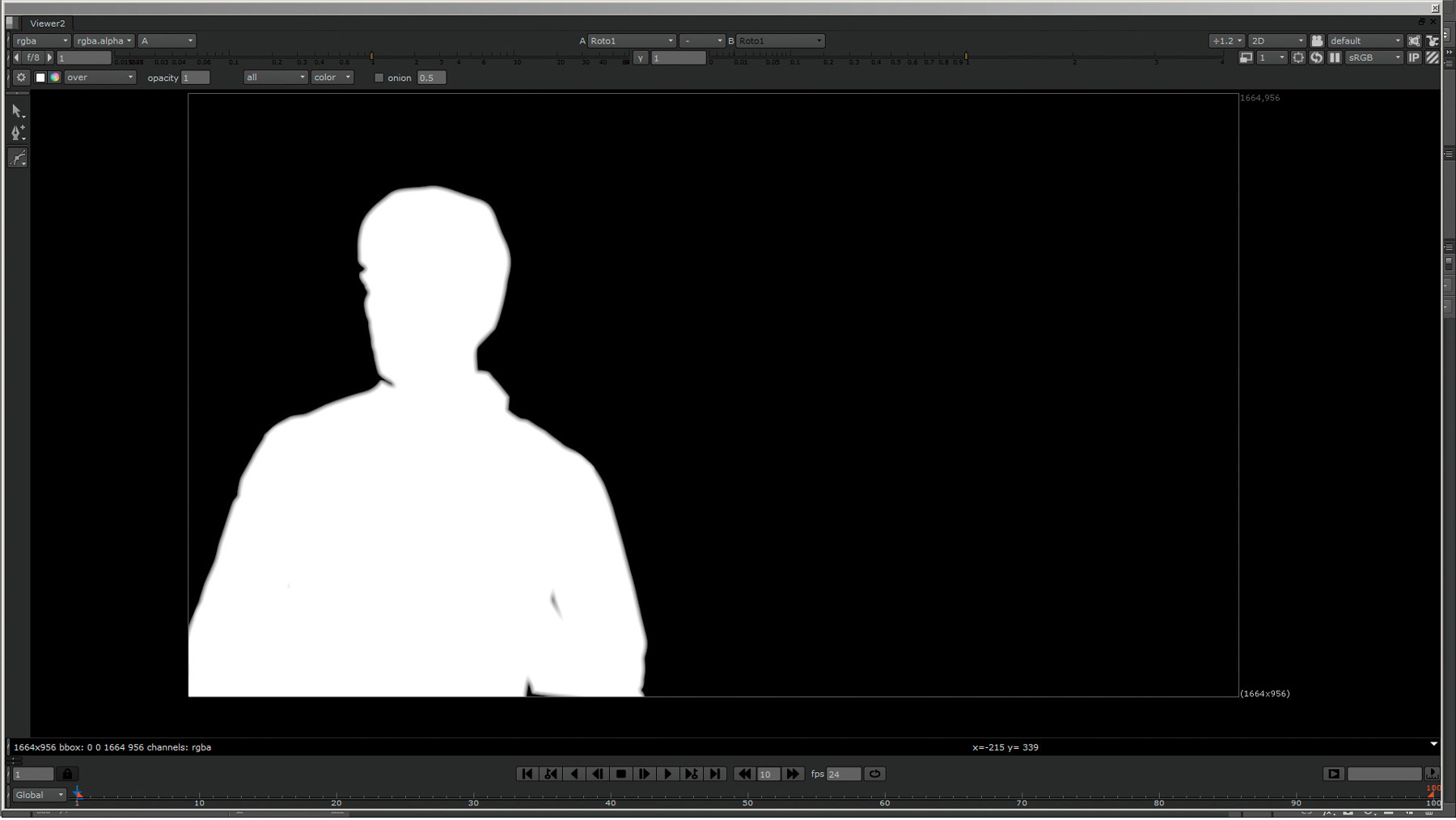
Figure 3.12. Isolated roto matte created to key only actor’s hair

In Figure 3.13 you can see the matte created by using a luminance key (a key based on luminance or brightness) isolated with the matte from Figure 3.12. If we combine this matte with the roto matte in Figure 3.14, we get a very nice fully matted actor, complete with fine hair details, as seen in Figure 3.15.
Figure 3.13. Detailed hair matte created by luma keying hair isolated with matte from Figure 3.12

Figure 3.14. Combined roto matte and overlay of isolated roto key area
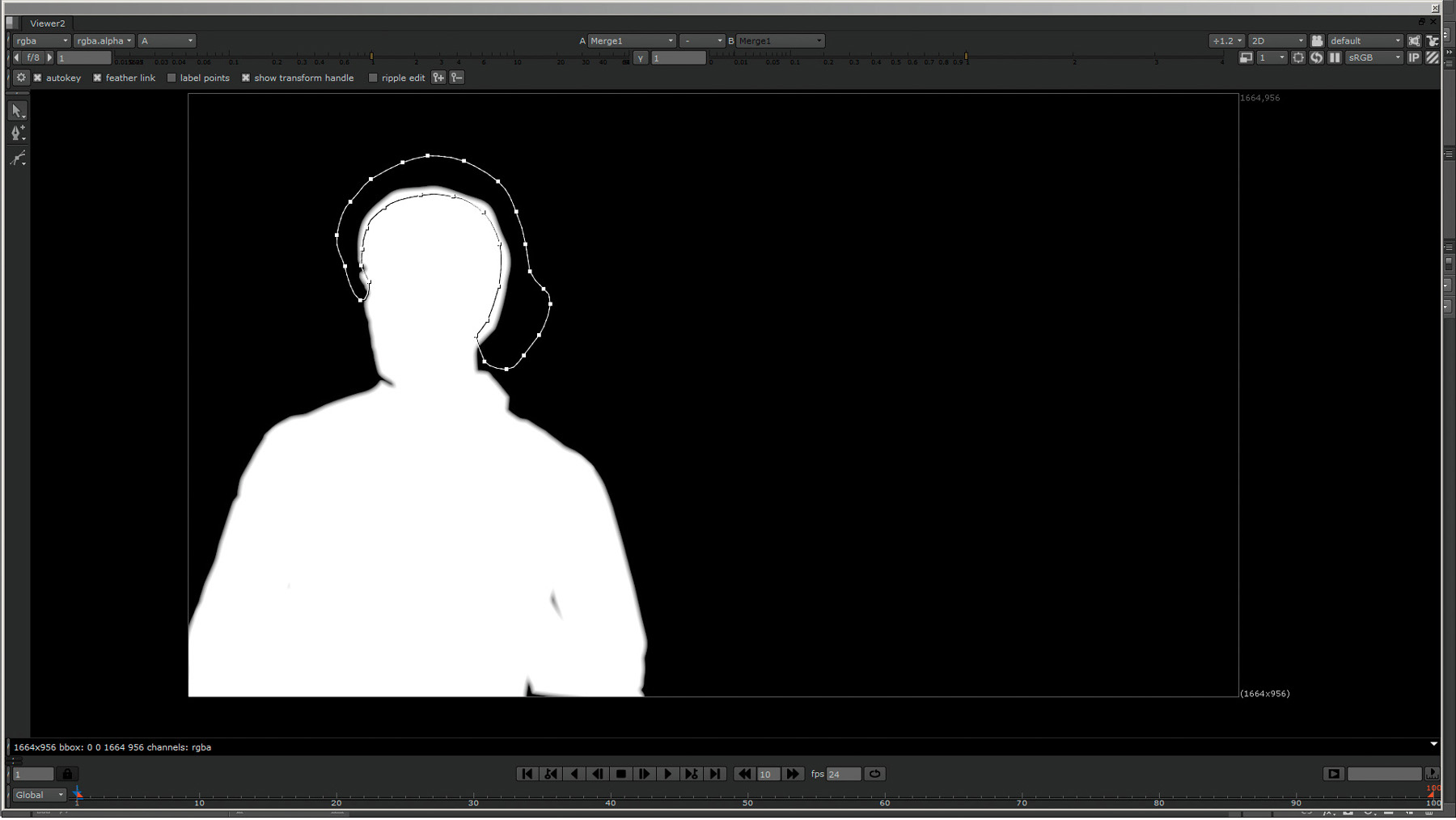
Figure 3.15. Finished matte, created by combining mattes from Figures 3.11 and 3.13

Roto Applications
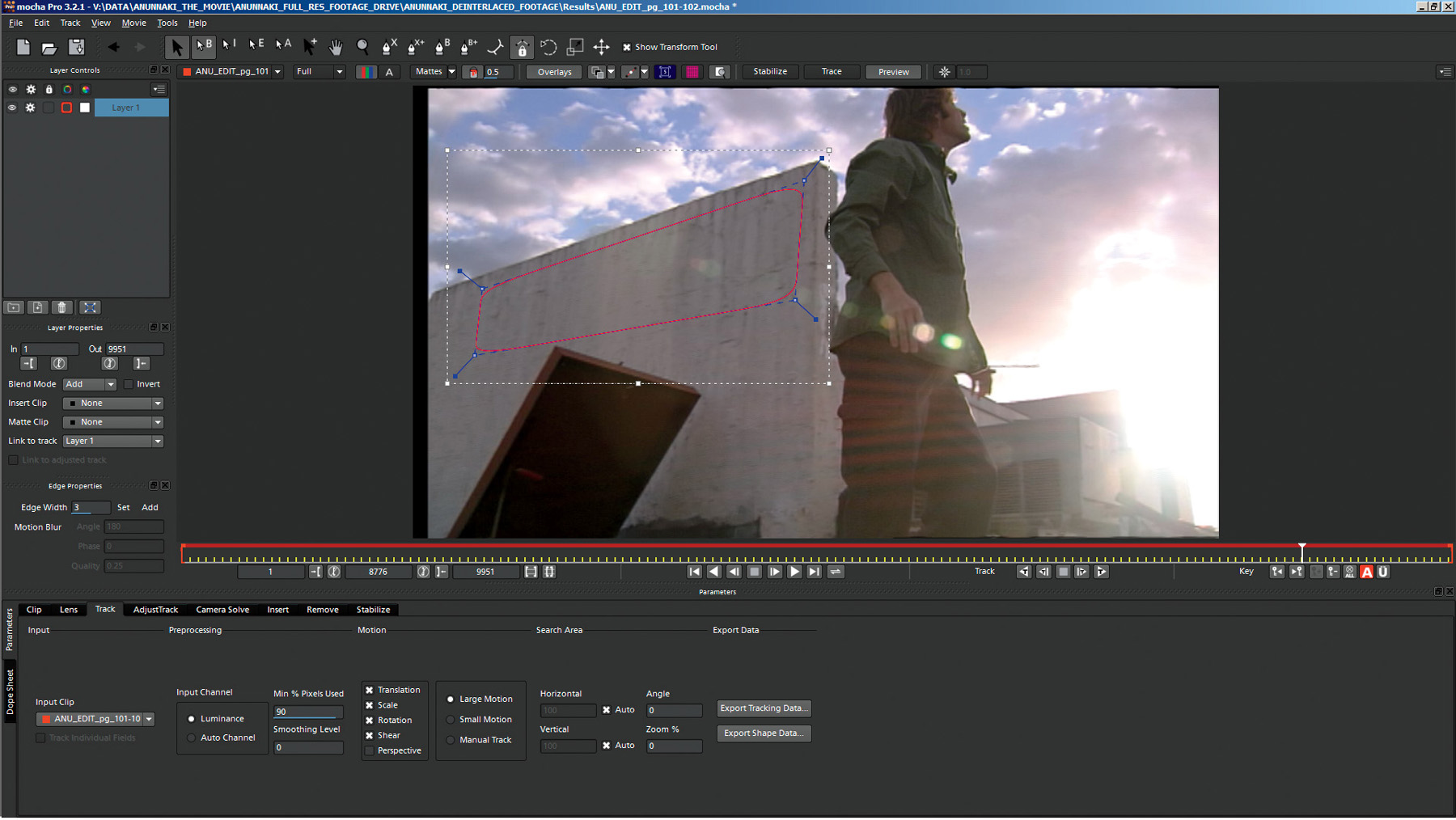
Although there are dedicated applications for sophisticated roto and tracker-assisted roto work, such as Imagineer’s Mocha Pro (seen in Figure 3.16) and Silhouette, almost all compositing applications (including Nuke, After Effects, Fusion, Shake, etc.) will have very capable roto tools, which all work basically the same way.
Figure 3.16. Mocha Pro planar tracking and roto application interface
2D Motion Tracking
Modern VFX artists don’t have the luxury their early VFX predecessors had—using still, or locked off, VFX footage (where great care was taken to ensure that the camera didn’t move at all to allow VFX elements to be more easily and perfectly aligned and integrated). Today, most VFX shots are going to be moving, and because of this, you have to have a way to integrate your VFX element using the same motion that is happening in the footage or it will be painfully apparent that your fake VFX element is floating awkwardly onscreen looking as if it were just poorly pasted on.
To ensure your VFX elements match and integrate perfectly, you will need to motion track, or track the motion, in the footage or sequence to which you will be adding an effect. In its simplest form, 2D motion tracking analyzes a specific set of pixels (which you identify) and then tries to follow those throughout the duration of the footage while recording the horizontal and vertical, or X and Y, coordinates. You can then use and reuse this set of data to move your VFX element in the scene to match the original camera’s motion, or to make it easier to integrate other features.
Anatomy of a Motion Tracker
A motion tracker will almost always consist of three parts (as seen in Figure 3.17):
Figure 3.17. A typical motion tracker
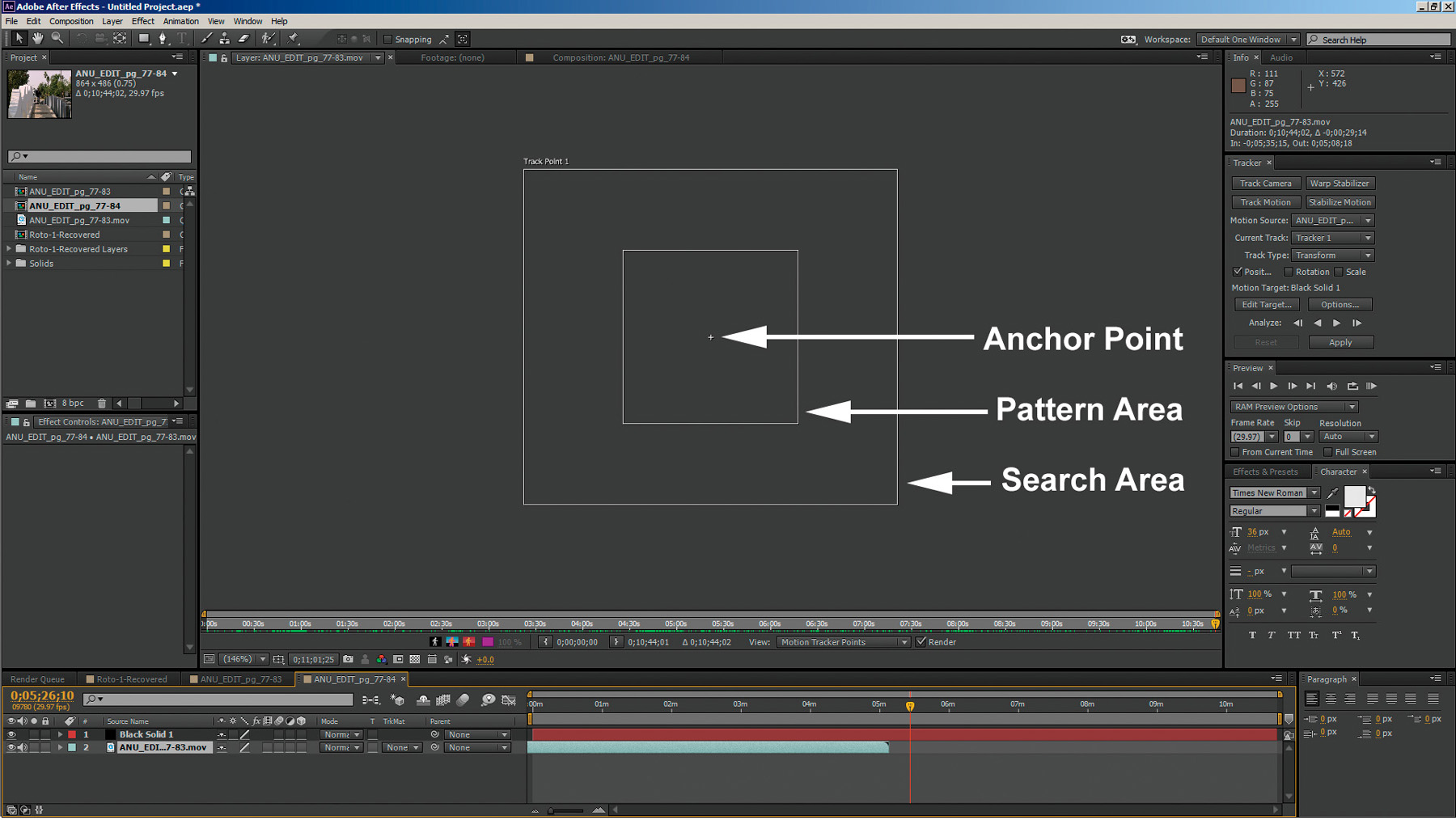
• The pattern area: This is the area defining the pattern that the motion tracker is to try to follow.
• The search area: This is the area or distance that the tracker will limit its search to, for the pattern defined in the pattern area, on any given frame.
• The anchor target: This is the point that any data will actually attach to.
Types of 2D Motion Tracking
There are a few different types of 2D motion trackers, each with its own purpose (and sometimes as a necessary fallback for another, when one doesn’t work).
1 Point
The simplest of 2D tracks is a 1 point track. A 1 point track uses one motion tracker (as seen in Figure 3.18) to track one pattern. This allows for the attachment of an element to the translational motion of the pattern being tracked in the horizontal and vertical, or X and Y, motion planes and is the goto workhorse tracking method for simple tracks or when all else fails.
2 Point
Adding a second tracker, as seen in Figure 3.19, adds two functionalities:

• The added ability to track relative rotation between the two trackers
• The added ability to track relative (faked) scale between the two trackers as they move closer together or farther apart
4 Point Cornerpin
Tracking with four trackers, as seen in Figure 3.20, adds
Figure 3.20. A 4 point cornerpin track

• The ability to pin or stick an image to common flat plane targets such as billboard signs, computer screens, and so on
• The added ability to warp four corners of an element to add perceived (faked) perspective
The Golden Rules of Motion Tracking
Just as in roto, there is a definite set of Golden Rules that should be followed to ensure the best and cleanest possible track with the least amount of noise or drift. Like the Golden Rules for r, engrain these Golden Rules in your memory; they are critical to good tracking and matchmoving work:
1. When selecting your pattern area, choose a pattern that has as many of these attribute as possible:
• Has high contrast
• Doesn’t change shape during the course of the footage
• Doesn’t change lighting appearance (reflective, flashing, etc.)
• Isn’t occluded during the footage
• Contains distinct high-contrast corners or angles or is completely surroundable as is the case with a circle or sphere
• Doesn’t contain long, continuous, unbroken lines or repetitive or similar patterns seen elsewhere in the scene
2. When selecting your pattern area, choose a pattern that is positioned
• For a 1 point track—as close to the position where the CG or VFX element will appear as possible (especially in depth, or z-space)
• For a 2 point track—as far apart onscreen as possible but in the same depth or z-space
• For a 4 point cornerpin track—as close to the corners of the area where the CG or VFX element will be placed in the scene
3. When selecting the search area, make sure to first analyze the footage to determine how far the point to be tracked moves on any given frame:
• Creating a search area that is too large will waste a lot of calculation, resulting in long track times, and is likely to lose the track mistaking something else in the image for the pattern area.
• Creating a search area that is too small will quickly lose the track as the pattern area to be tracked moves outside of the area to be searched.
• Creating tiny pattern or search areas can result in the tracker thinking film grain or video noise is motion and tracking it, thus resulting in a very jittery or noisy motion track.
4. Although the anchor point may be in the middle of the pattern area, it doesn’t necessarily have to be. A common mistake is to assume it is the center. The anchor point can be placed anywhere in the scene (even outside of both tracking boxes) and is the point to which the motion data will be attached.
5. It is perfectly correct and common to start tracking from the beginning and work forward, start at the end and work backward, start in the middle and work forward, then backward, and so on. Many times you will have to work in small segments as well as the subject you are tracking becomes occluded in areas.
Comparing Good and Bad Tracking Targets
Take a look at Figures 3.21–3.28 in which you can compare a few good and bad tracker targets.
Figure 3.21 shows an example of a good 1 point tracker location. It has high contrast, is singular, and has a well-defined vertical and horizontal angle pattern with a search area that is not too large or too small.
Figure 3.21. Good 1 point tracker location

Figure 3.22, on the other hand, shows poor 1 point tracker placement. In this case the tracker has been placed along a straight edge. Although this pattern area does have high contrast, there is nothing to lock onto vertically, so it not lock on and will slide around on the horizontal edge.
Figure 3.22. Poor 1 point tracker placement

Figure 3.23 shows an example of good 2 point tracker placement. This location has both high contrast and well-defined vertical and horizontal angle patterns, has the trackers placed a good distance apart, and has search areas that are not too large or too small.
Figure 3.23. Good 2 point tracker placement

Though the 2 point tracker placements in Figure 3.24 have high contrast and well-defined vertical and horizontal angle patterns with search areas that are not too large or too small, this would be considered an example of poor placement because the trackers are placed too close together and rotational errors will be hugely amplified (see the following section, “2 Point Tracker Placement: Rotation and Scale Error Amplification”).
Figure 3.24. Poor 2 point tracker placement

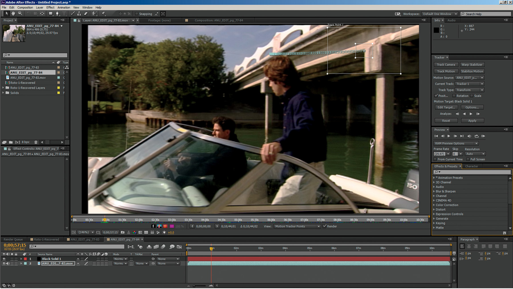
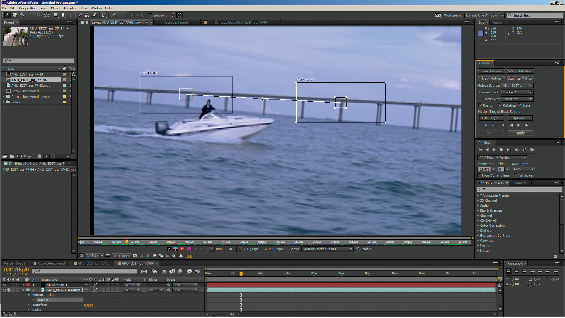
Figure 3.25 is also an example of poor 2 point tracker placement. It does exhibit high contrast and well-defined vertical and horizontal angle patterns, and trackers that have been placed fairly wide, the search areas are too large and will cause long tracking times and tracking errors where the trackers will likely jump to very similar looking nearby bridge pylons that are also within the search area boxes.
Figure 3.25. Another example of poor 2 point tracker placement
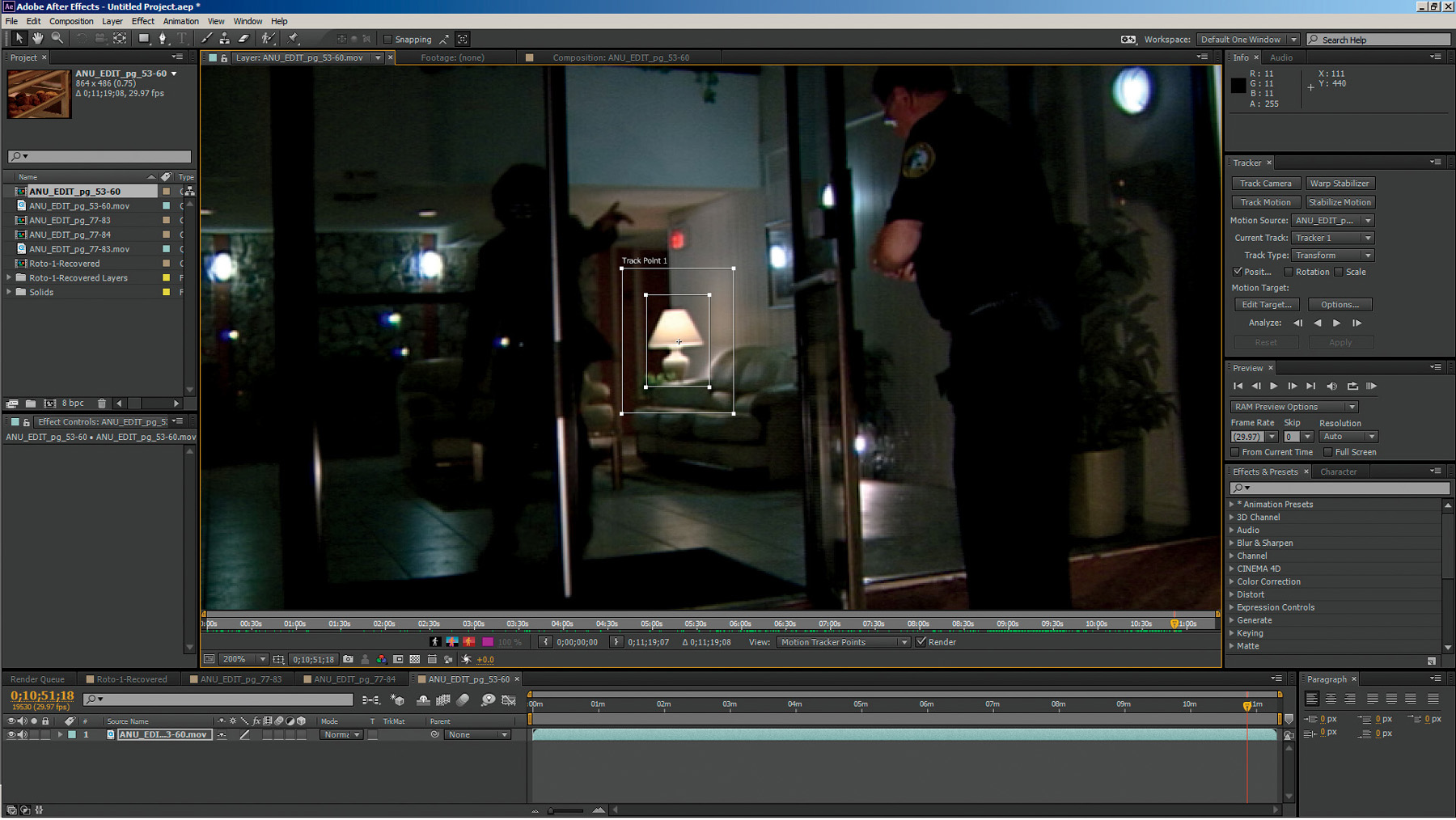
Although at first glance the tracker placement in Figure 3.26 might appear to be a good 1 point motion tracking target for an element to be placed in the distance near the palm tree, and although this example is high contrast and fairly “surroundable,” remember that palm trees sway in the wind, which will likely result in erroneous tracking data (you wouldn’t want your CG building swaying, would you?).
Figure 3.26. A good example of a 1 point tracking target—or is it?

Figure 3.27 shows another poor example of 1 point tracker placement. In this image, the leaves on the tree are far too similar to all of the leaves in the entire group of trees. These leaves are also likely to move randomly in the wind, which will result in a very inaccurate, noisy/jittery, track and data.
Figure 3.27. A further example of poor 1 point tracker placement

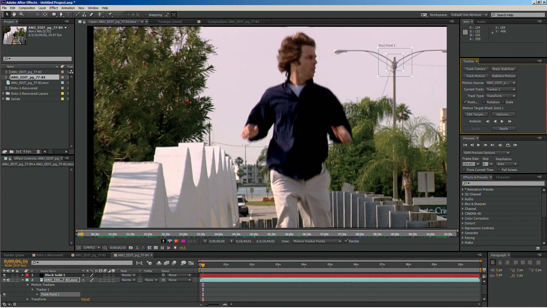
Figure 3.28 shows one more example of good 1 point tracker placement for an element that will be placed near the light pole in z-space. Like the palm tree in Figure 3.26, this is a good high contrast target, but it is in fact much better than the palm tree because it also contains almost perpendicular angles and is a fixed target that doesn’t move.
Figure 3.28. Good 1 point tracker placement
2 Point Tracker Placement: Rotation and Scale Error Amplification
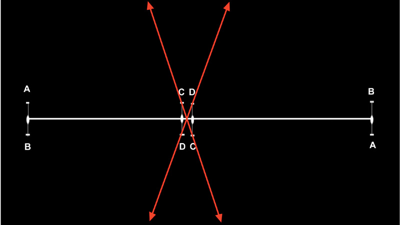
When approaching a 2 point tracking shot, it’s critical to understand the concept of error amplification. If you select tracking points for a 2 point track on a simple scene like the one shown in Figure 3.29, and you place your tracking points as far apart as possible (in this case, the first tracker at the center point between the left A and B and the second tracker at the center point between the right A and B) where the distance between each A and B is assumed to be the distance of error in the track, you get an error rotation up of about 5 degrees and down of approximately 5 degrees, totaling about 10 degrees of rotational error. Any element we attach to that tracking data will rotate through that 10 degrees of error, as illustrated in Figure 3.30.
Figure 3.29. A simple scene for 2 point tracking with error distance points A, B, C, and D, all exactly the same distance from the center line.

Figure 3.30. With trackers set far apart, the total rotational error is about 10 degrees in this particular example, which would impart a slight rocking of the element to which you attach the tracking data.

If we place the tracking markers very close (at the point between the leftmost C and D and between the rightmost C and D) with the same distance of error, we now have a rotational error of plus and minus 70 degrees, or about 140 degrees of total rotational error, as shown in Figure 3.31, which would have our element rotating wildly. This error amplification effect works the same with scale. In instances where you have no choice but to use tracking points that are close together, it’s a good idea to disable the tracking of scale, rotation, or perhaps even both.
Figure 3.31. With trackers set close together, the total rotational error skyrockets to about 140 degrees in this particular example, which would have the element you attach the tracking data to rotating wildly.
2D Motion Tracking Applications
Most good compositing applications contain capable 2D trackers and all follow similar conventions as to the design and functionality of the look and operation of motion trackers.
After Effects
After Effects has a great 2D motion tracker that is very fast to use with its pickwhip (“drag and connect”) functionality (shown in Figure 3.32).
Figure 3.32. After Effects’ motion tracker
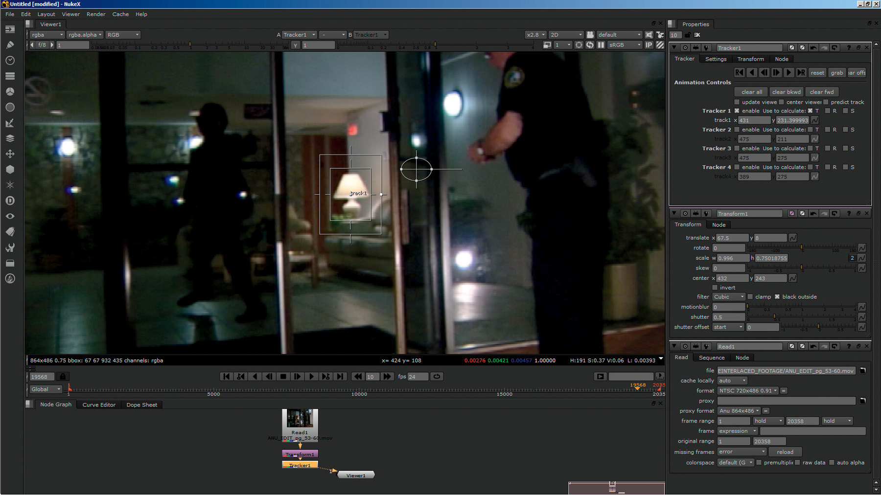
Nuke and Fusion
Nuke (Figure 3.33) and Fusion, which are both nodal-based compositors, contain excellent 2D tracker nodes that look and operate almost identically to the ones in After Effects.
Figure 3.33. Nuke’s motion tracker
Planar Tracking
As you have seen, most of the 2D trackers rely on a definite high contrast “pattern” so they are able to track a subject. One exciting and relatively new spin on tracking has appeared in a technology called planar tracking. True planar tracking differs from point tracking in that it tracks entire planes, every pixel, and thus it can do an amazing job of sticking to a track when point trackers fail.
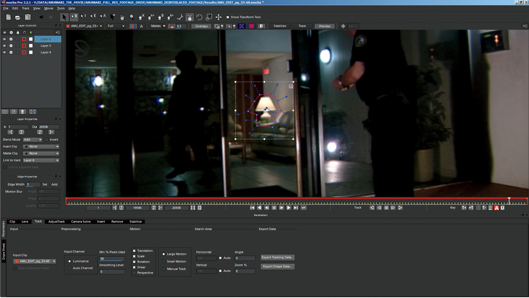
Mocha Pro
One such specialized planar tracker is Mocha Pro (seen in Figure 3.34). Mocha Pro uses X-Splines to surround and define a pattern of pixels on a plane and then tracks every pixel in that pattern to obtain amazing results. New versions of Mocha Pro are also able to determine some 3D planar tracks that are calculated from multiple 2D planes on a different axis.
Figure 3.34. Mocha Pro’s planar tracker with an X-Spline outlining pattern to be tracked
Tracker Assisted Roto
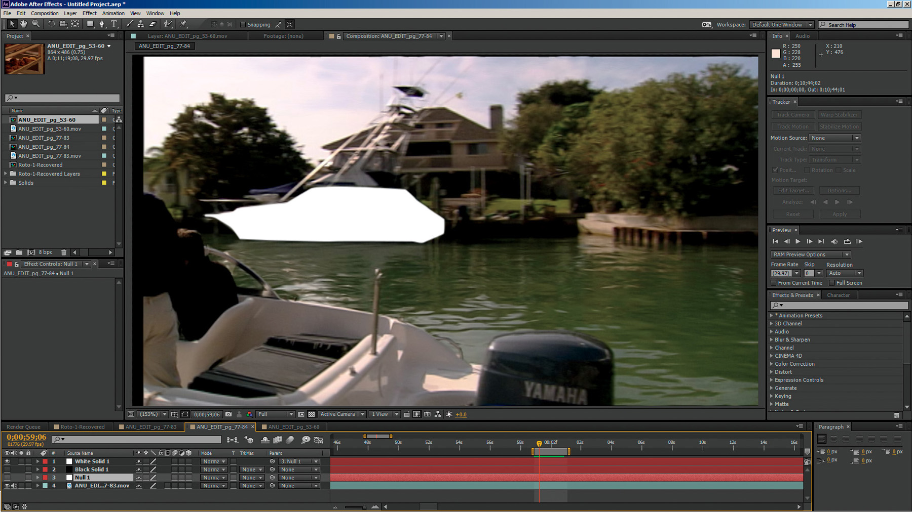
One huge advantage of breaking up subjects to be roto’d into many separate individual shapes is that they can be attached to tracking data to assist in semi-automating the rotoscoping process. For example, if you needed to rotoscope the bottom section of the boat in the background in Figure 3.26, you could roto the boat and keyframe the rotoshapes by hand, or you could create just one shape for the boat as seen in Figure 3.35 (since it is a fairly rigid object), 1 point track the scene, as seen in Figure 3.36, and then simply apply that tracking data to the shape, as seen in Figures 3.37 and 3.38.
Figure 3.35. Simple rotoshape for the bottom of the boat in the background

Figure 3.36. 1 point track of the corner of the boat window

Figure 3.37. Rotoshape attached to 1 point tracking data
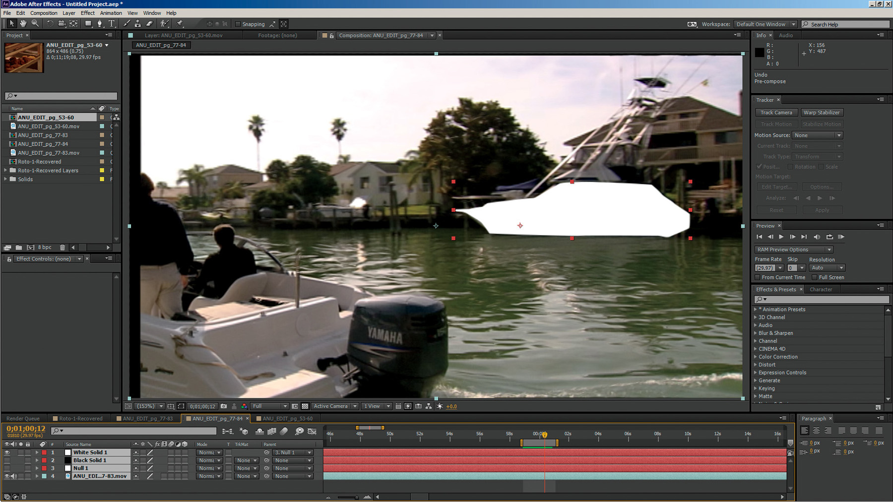
Figure 3.38. Almost perfectly automated animation of roto via tracker assist
2D Matchmoving
2D tracking, of course, is only the first half of the task at hand. The whole reason for tracking our scene is so that you can place something into the scene that moves along with the scene as if it was there when the footage was originally shot. You will do this by the process known as matchmoving. In the old days, matchmoving was done entirely by hand. A matchmover would literally match the move of the footage. In those days, matchmoving was an entire profession (and still is in very high-end VFX companies). Today, however, it is very common for a VFX artist to have to do his own matchmoving.
The process of matchmoving is part technical, part art, and some would argue, part magic. If you have done a perfect track, a matchmove is almost an automatic process. If you haven’t, or if a good track isn’t possible, then it becomes anything from a clever work of art to a complete point-nudging nightmare. The point here is that every step in the process is cumulative. If you take great care to do your tracking well, the matchmove goes smoothly. The opposite is also true, of course.
For a simple example, let’s build some quick sunglasses out of nothing but rotosplines, track the original footage, or plate, of our actor (seen in Figure 3.39), and then matchmove the sunglasses to his movement. Since the shape of these doesn’t have to be animated, we can create them with just two shapes: an outside frame shape and an inside lens shape (created by just scaling down the outside shape and applying a slight bevel effect and a little transparency, as you can see in Figure 3.40).
Figure 3.39. Actor Chad Ayers filmed against a bluescreen
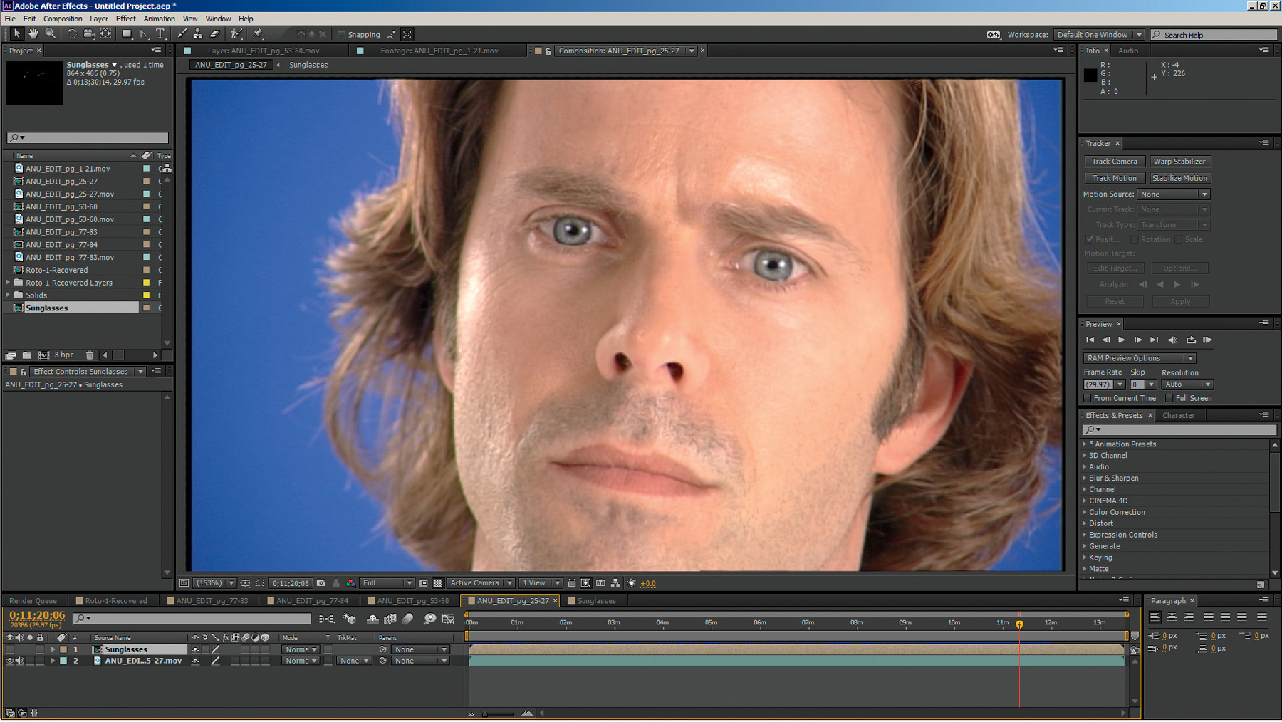
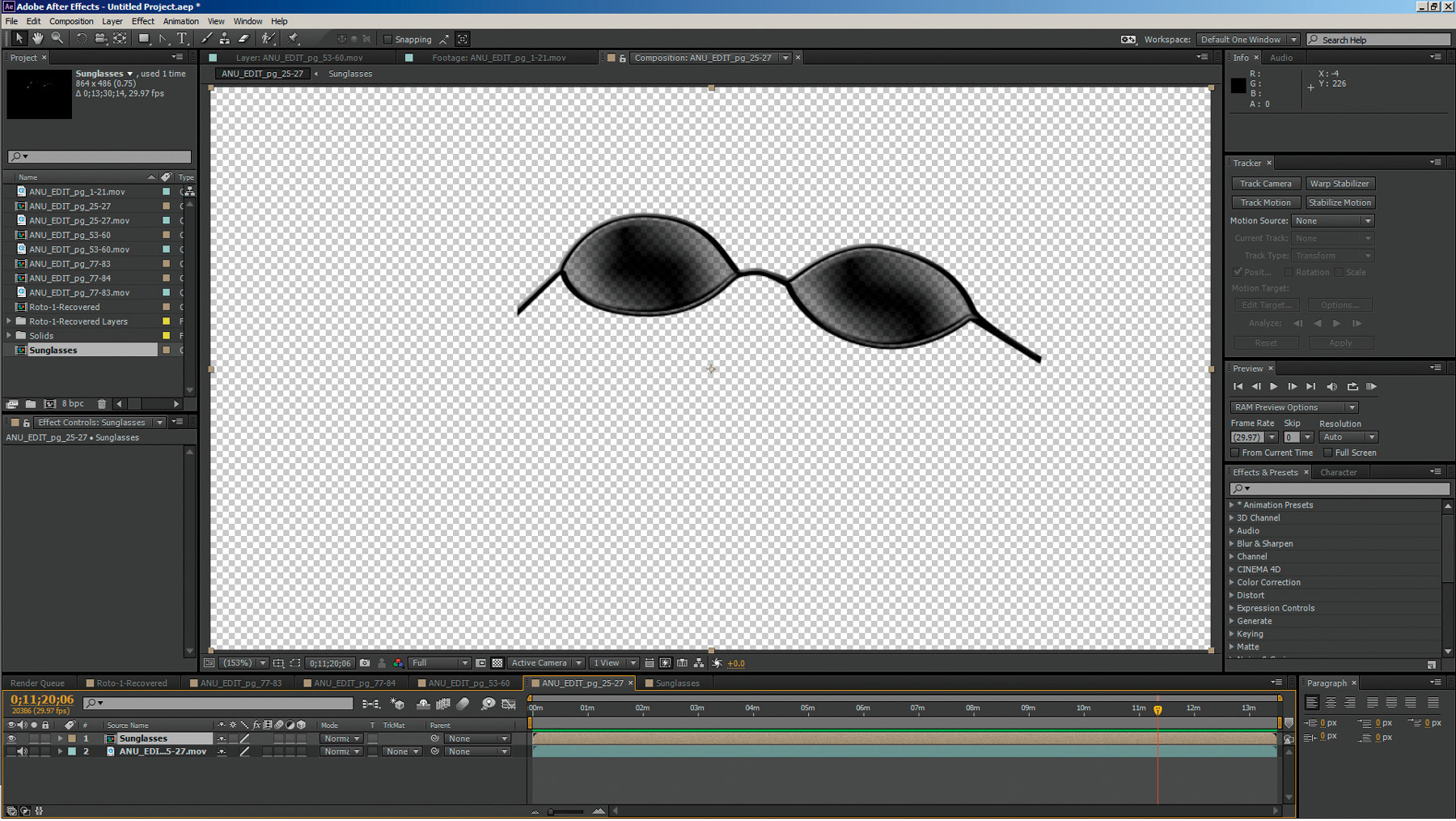
Figure 3.40. Our quick and dirty rotospline sunglasses
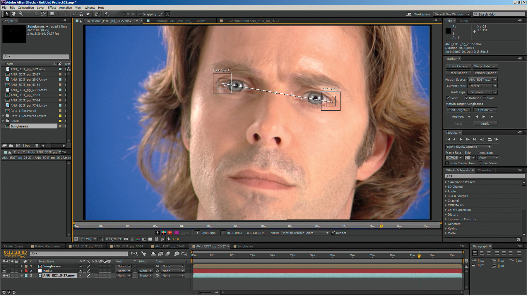
Next, we’ll track his eyes using a 2 point track. Since he isn’t moving toward or away from the camera, we won’t be tracking for scaling, only position and rotation.
Tracking an actor’s face can be tricky as many parts of the face can move (such as the corners of the nose, mouth, ears, eyebrows, etc.). It’s best to try to stick to areas of the face that are pretty much anchored, conveniently in this case, like the corners of the eyes as shown in Figure 3.41.
Figure 3.41. 2 point trackers set to track corners of eyes
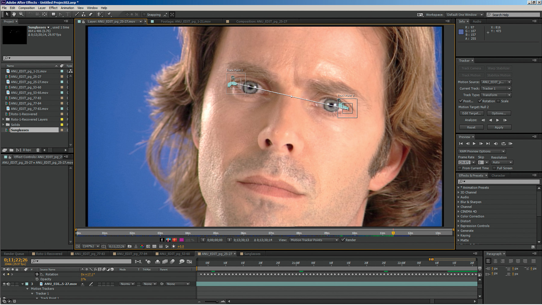
This gives us a pretty good track with only position and rotation keyframes, which you can see as small diamonds on the timeline in Figure 3.42.
Figure 3.42. 2 point track with keyframes on the timeline
Now, all that’s left to do is to position the layer with the sunglasses onto our actor (Figure 3.43) and then attach the tracking data from our 2 point track to the layer with our rotospline sunglasses for them to be matchmoved.
Figure 3.43. The sunglasses layer positioned into place
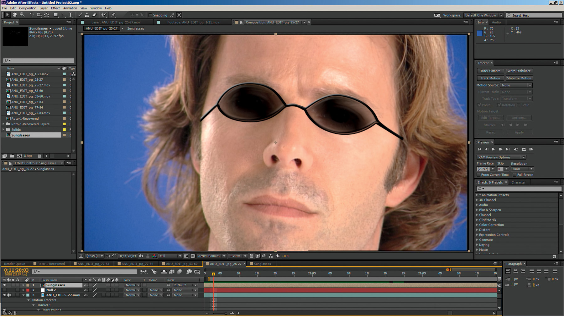
Figure 3.44. Our quick and dirty sunglasses matchmoved onto our actor made out of nothing but rotosplines

Stabilization
If you think of the data we obtain from tracking an object in a scene with a 2D motion track as merely finding the position of that object at each frame and then recording that information in a series of numeric XY coordinate data (which it literally is), you can take that process one step further and apply the inverse, or negative values, of that data to the entire sequence, which will move the footage, or plat, in the opposite direction of the object’s movement every frame, thus stabilizing the plate around the object. The object will appear to be perfectly still, whereas the entire plate appears to move and float around it.
Stabilization is very handy for doing complex shots on footage that additionally has complex camera movement embedded in it as well. Stabilizing the plate allows us to work on what appears to be a locked-off shot.
Destabilization
Once we’ve completed any VFX work on a stabilized shot, we will need to replace the original camera movement back into the shot. This process is known as destabilization and is performed by simply reapplying the original motion tracking data back to the entire plate again (reversing the stabilization back to the original camera motion, but with the VFX now added and appearing to move as if it was part of the original photography). This is a very powerful technique that we will cover in more detail in many later chapters.
Advanced 2D Tracking Strategies
Sometimes, trackers just don’t work. No matter what you do, there’s just not enough to lock onto, or something keeps occluding the frame and throwing the tracker off, or there’s just nothing to track, as in the case of Figure 3.45, where you can see a sequence shot on greenscreen with no tracking markers. At first glance it may seem like there is nothing on the background wall to track. But if you use the same trick you learned in Chapter 2 to pull your grunge maps and add a new trick, we can make this work.
Figure 3.45. Actors shot against greenscreen with no tracking markers or clearly definable high contrast features

First, you will need to look through the individual RGB channels (Figures 3.46–3.48) to see which has the most information for the background greenscreen wall.

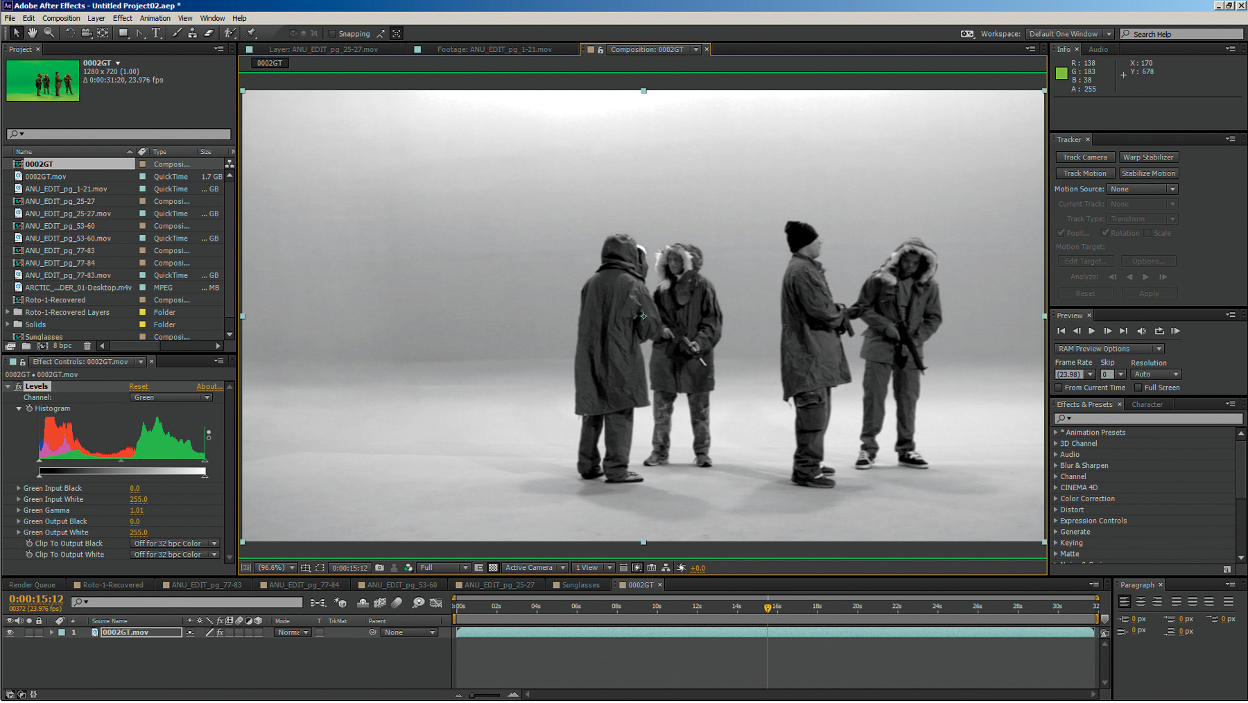
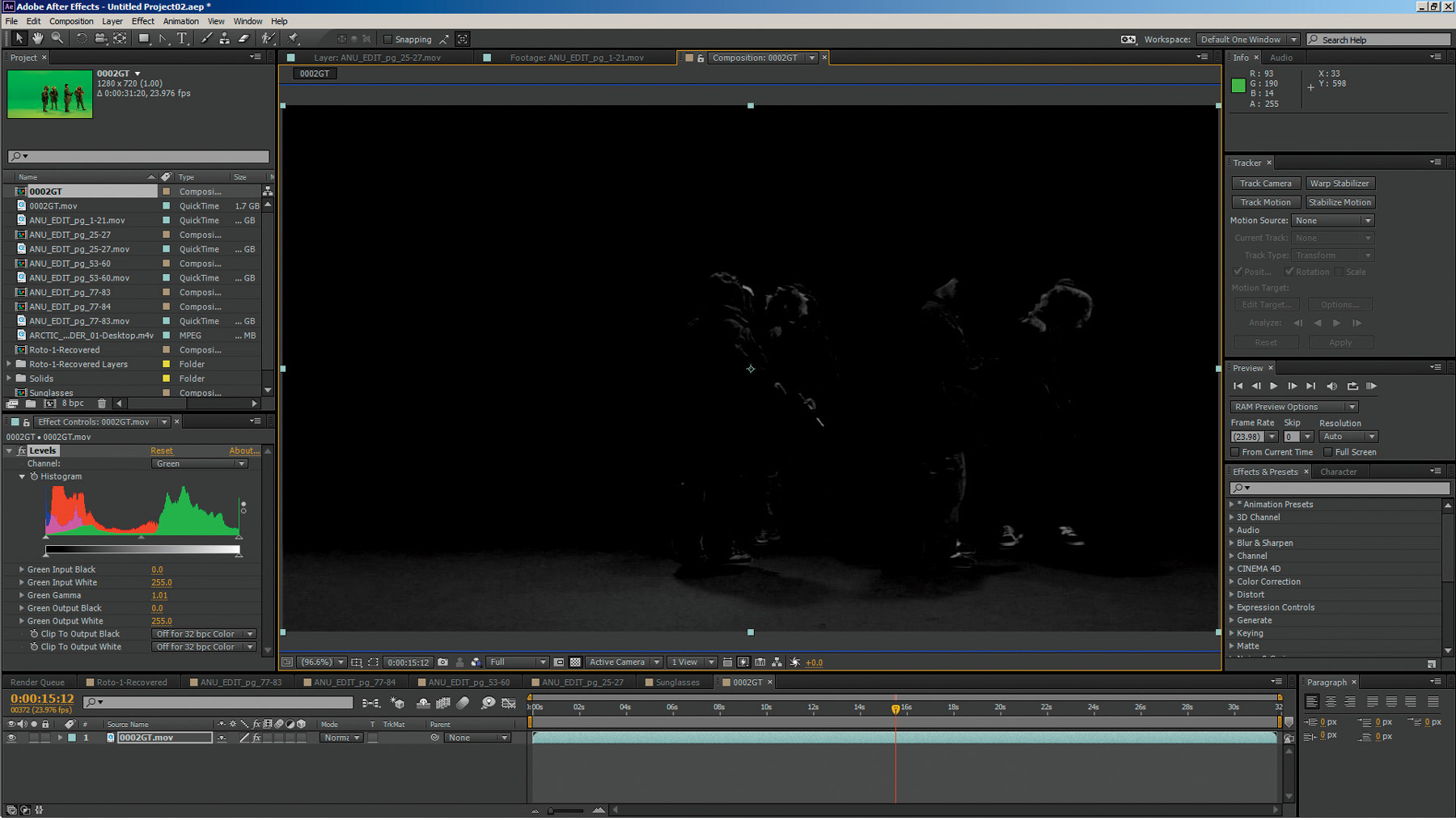
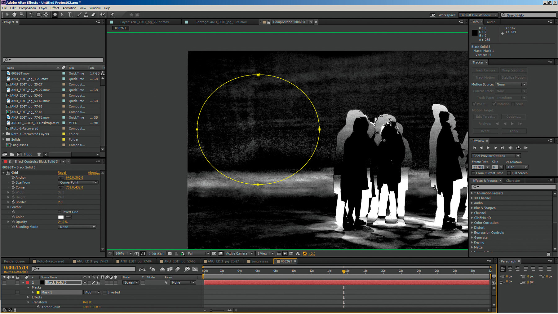
You can see that the green channel, of course, has the most data for the greenscreen background. Add a levels adjustment to the green channel, crush the black levels and lighten the gamma a little, the same way we did in Photoshop to pull the grunge maps from the dirty warehouse floor in Chapter 2. Lo and behold, the drywall seam in the greenscreen background emerges, forming the cross you see in Figure 3.49 and Figure 3.50, as if by magic!
Figure 3.49. Crushing the black levels and raising the gamma reveals the drywall seam on the greenscreen background.

Figure 3.50. Cross formed from drywall seam

Now, this feature still isn’t quite defined enough for a tracker to follow, but it is definitely defined enough for our human eyes to discern and follow. So get ready to get down into the trenches. We’re going to have to do this one by hand.
Hand 2D Matchmoving
There are many techniques that can be used to perform hand tracking. Hand tracking is basically just hand keyframe animating—yes, the same type of keyframe animating that you did creating the rotosplines! Consequently, the same rules apply when determining what frames to make your keyframes.:
• When you are animating a hand track, find the frame in which the subject moves farthest away from your tracker’s position before either changing direction or moving back toward the original position. That is the point at which you want to place your keyframe. After you’ve placed your keyframe, find the next farthest point the target moves to before either changing direction or starting to move back toward this position and place your next keyframe at this frame. Continue this process until the track is locked to the motion.
• The object is to set as few keyframes as possible. Doing so will deliver the cleanest and smoothest animation possible.
• It is perfectly correct and common to start from the beginning and work forward, start at the end and work backward, start in the middle and work forward then backward, and so on. Many times you will have to work in small segments as well.
“But what,” you are surely asking “do I use to actually do the tracking with?”
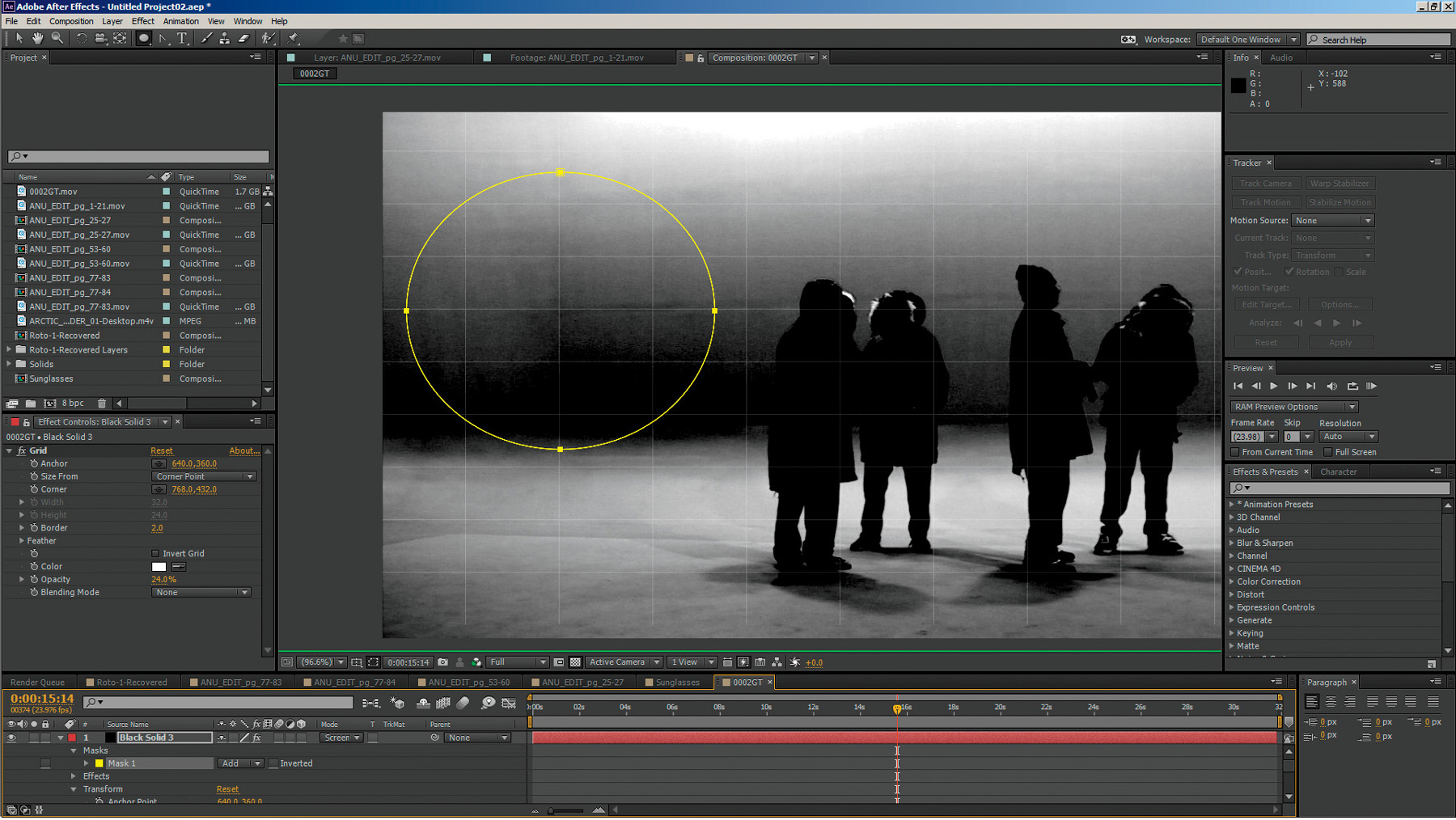
Some people recommend using a layer with a grid to overlay your scene, keyframe animating that layer (matching lines and intersections on the grid to features in the scene you are hand tracking as seen in Figure 3.51) and then using that data as your tracking data. The data you are recording when setting keyframes on a layer is the same type of XY position data the tracker is recording. Over the years, I’ve devised a very clever trick which works much better and is a lot more precise. I call this “Using the footage to track itself”!
Figure 3.51. Grid method of hand tracking—using a grid overlay to line up features of a drywall seam
The way this works is to take a frame of the footage—one that contains the most detail, has the best contrast, has the most features in frame, and so on (you can use multiple frames as well)—and copy this still frame onto another layer.
Set the duplicate layer on top of the footage you want to track and set this layer’s transfer or blend mode to a difference blend mode. The screen should go completely black. That is exactly what you want! If it doesn’t go completely black, you need to line up your still’s position in the timeline until it matches exactly and goes completely black. It’s going completely black because you have its blend mode set to difference and there is no difference at this point. Set your first keyframe at this completely black frame (Figure 3.52) and then move ahead in the timeline following the guidelines for where to set your keyframe at the widest point of divergence. At that point, your frame should look like a strange negative with ghosted areas like the ones in Figure 3.53.
Figure 3.52. Perfectly aligned still (tracking frame layer)
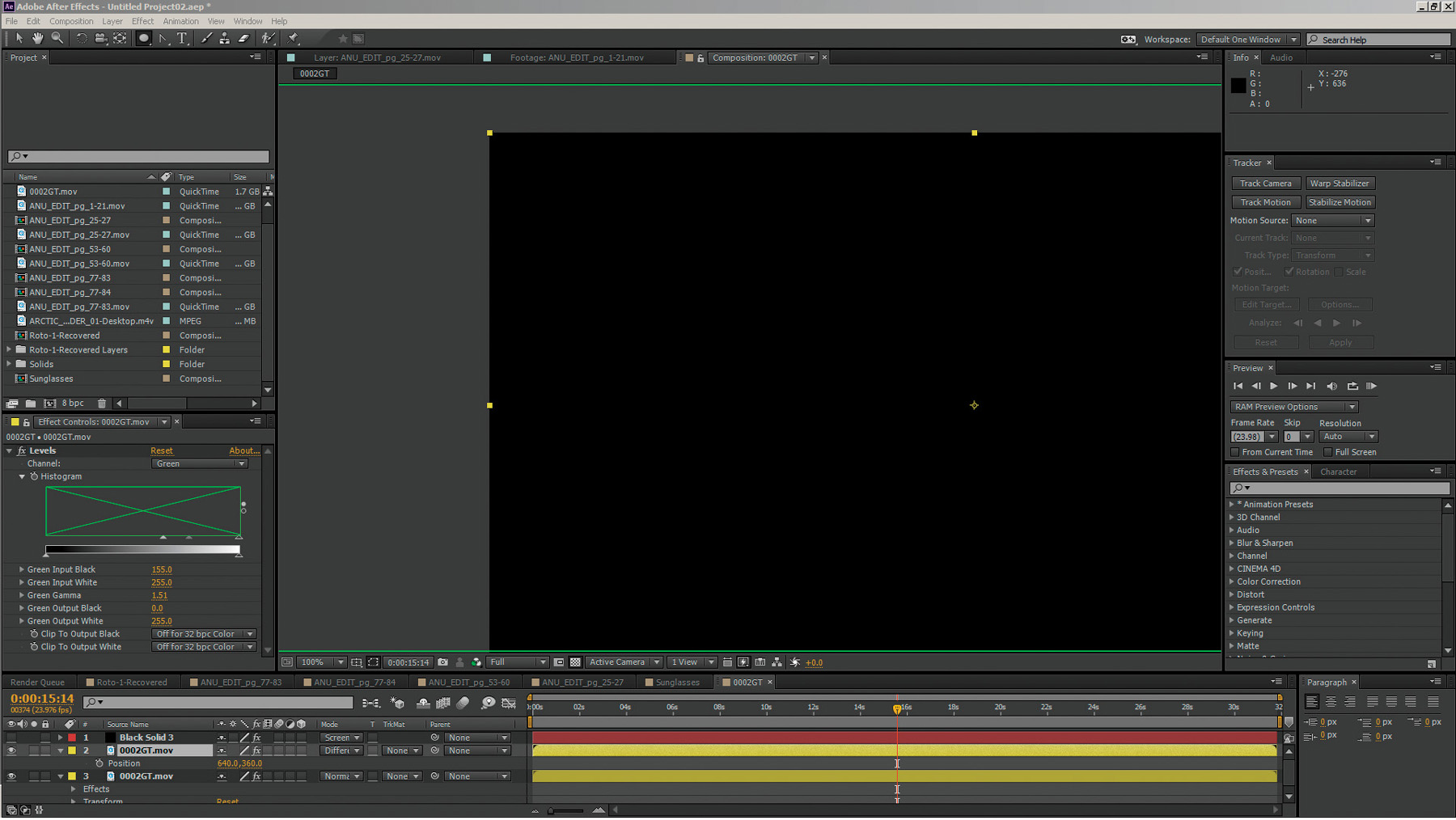
Figure 3.53. Ghosting reveals the “difference” in position of the tracked features of the greenscreen wall from the still tracking layer
Simply look for your target (in this case the cross formed by the drywall seam), move the layer back until it lines up perfectly and goes black again, then repeat the process until all your keyframes are done and the footage stays black throughout the entire process. Anywhere it drifts or you see ghosting, you’ll need to go back and set another keyframe at the new widest divergence point.
Using this “widest divergence” method of keyframe placement helps prevent unnecessarily keyframe-heavy tracking and animations and should be applied to any keyframe animation activity you do.
Once hand tracking is completed, the VFX element can simply be parented or connected to the keyframed still layer, or the positional animation data can be copied and pasted to the target element.
Now that you have a good idea of what you’ll need in the way of 2D skills, it’s time to jump into the third dimension of 3D for VFX!