
Chapter 2
Hunter-Killer
Unlike the lowly maintenance bot, the hunter-killer has become a staple in nearly every science fiction video game and film. Less intellectually sophisticated than a droid and not as heavily armored as a mech, hunter-killers are antipersonnel bots designed for maximum agility over any terrain.
While most people credit James Cameron for the creation of the hunter-killer in Terminator II: Judgment Day, I would argue that the first hunter-killer I ever saw was in 1979. I speak of Don Coscarelli’s dreaded chrome ball from the movie Phantasm. Like most hunter-killers, the chrome ball was capable of hovering and fast pursuit, and had a limited form of artificial intelligence as well as the single purpose of killing people.
While I still find the prospect of a chrome ball hooking itself into my flesh and drilling a hole into my brain to be chilling, it’s just not that interesting to model. So … we are going to go the route of the HKs from Terminator II and Deus Ex II.
 Urgent: This is a very high-polygon model, meaning you’ll need a fast machine and a lot of memory. So why include it? Well … there are a lot of interesting things to build and learn in this chapter (e.g., making working pistons). If you don’t feel your computer can handle the whole thing, just do the parts that interest you (e.g., the engines). I actually prefer to build high-poly models because I love their intricacies and the way they look when they ’re done.
Day 1: Building the Eye-Pod
1. Create a Sphere with a Radius of 30 and 32 Segments.

Figure 2-1
2. Switch to the Front view, turn on Angle Snap, and Rotate 90 degrees in the Y axis so that the poles are now on the right and left sides instead of the top and bottom.

Figure 2-2
3. Convert it to an Editable Polygon and select the 320 large polygons that make up the middle of the sphere.

Figure 2-3
 Don’t Forget: It helps to switch back and forth between wireframe and shaded mode (F3) when selecting polygons, especially in tricky objects like tubes.
4. Click Detach and label the object eye_pod.
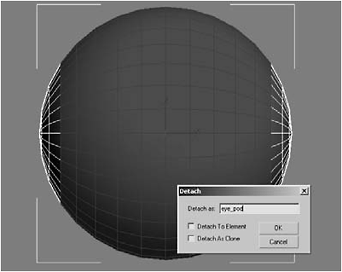
Figure 2-4
5. Rename the remaining two sides eye_brace and hide them.
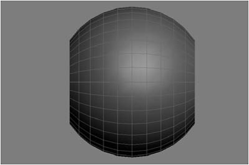
Figure 2-5
6. Using AutoGrid, create a Tube that is roughly the size of the smallest polygon on the eye_pod’s surface.
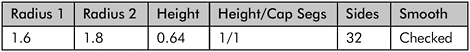

Figure 2-6
7. Convert the tube to an Editable Polygon, rename it eye_socket, and delete the back-facing polygons (i.e., the ones facing the sphere that no one will see). Then select the polygons inside the eye_socket and delete them too.

Figure 2-7
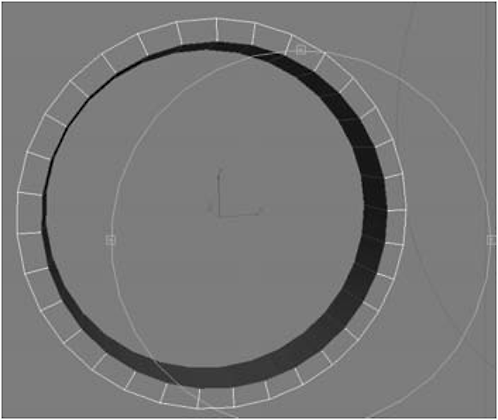
Figure 2-8
8. Select the outer and inner edges of the tube and Chamfer them, first by 0.03 and then by 0.01.
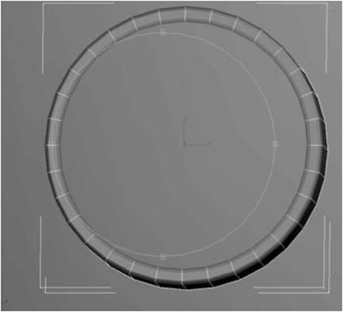
Figure 2-9
Don’t Forget: You don’t need to Chamfer the edge facing the eye_pod because it’ll be beneath the surface and not visible.
9. Using AutoGrid, create a Sphere in the center of the eye_socket with a Radius of 1.616, 32 Segments, and 0.5 for the Hemisphere setting. Use the Move tool to raise the sphere to the lip of the socket.

Figure 2-10
10. Convert the sphere to an Editable Polygon, rename it eye_ball, and delete the back-facing polygons (those facing the eye_pod); this is easier to do in wireframe.
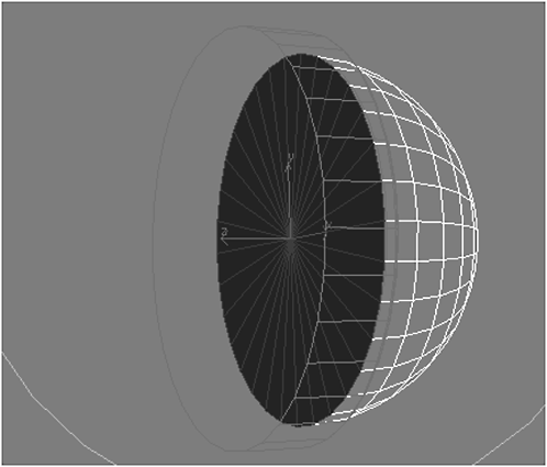
Figure 2-11
11. Select the eye_socket panel, attach the eye_ball, then switch to Vertex selection mode, select all the vertices on the eye_socket and the eye_ball, and click Weld (using a threshold of 0.01) to weld them together into a single object (vertices should drop from 577 to 542). Rename the merged object eye.
12. Select the eye_pod and the eye and hide them.
13. Unhide the eye_brace and delete one side (we’ll Mirror it later).
14. Switch to the Right view and zoom in on the eye_brace. Create a Sphere using AutoGrid with a Radius of 0.75, 32 Segments, and 0.5 for the Hemisphere setting and name it rivet.
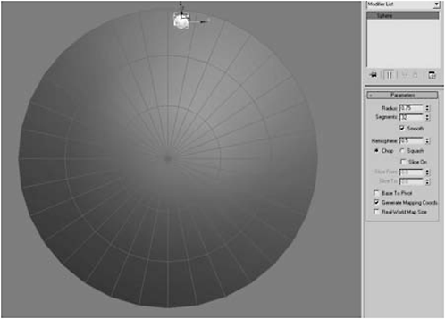
Figure 2-12
15. Convert it to an Editable Polygon, then switch to Perspective view, select the back-facing polygons, and delete them.

Figure 2-13
16. Switch to the Right view (if you switched the view in the previous step), click the Hierarchy tab, and click Affect Pivot Only.

Figure 2-14
17. Use the Move tool to move the rivet’s pivot point to the center of the brace. Turn off Affect Pivot Only.
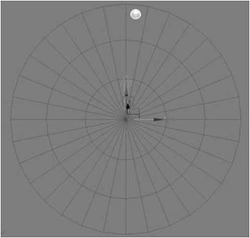
Figure 2-15
18. Select the Rotate tool, hold down the Shift key, and rotate –11.23 degrees in the Z axis. Then select Copy and type 31 for Number of Copies. Click OK.
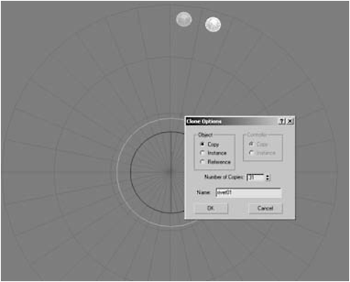
Figure 2-16
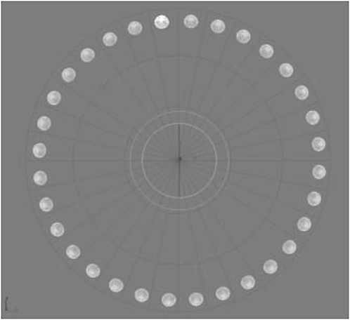
Figure 2-17
19. Arc Rotate around the bracket in the Perspective view to make sure all the clones are penetrating the brace.

Figure 2-18

Figure 2-19
21. Unhide the eye_pod.
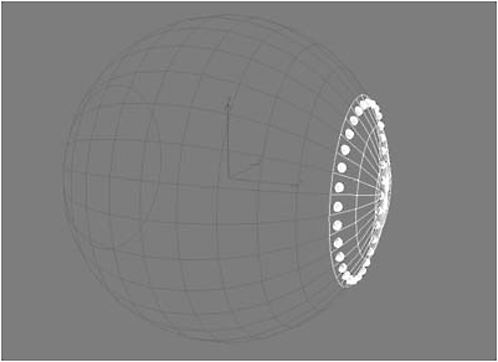
Figure 2-20

Figure 2-21
23. Select the eye_pod, click Attach List, and attach the braces to the eye_pod.
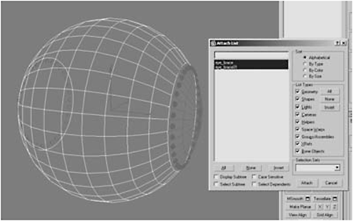
Figure 2-22
24. Select the center 32 polygons on both braces, delete them, and then Cap the borders.

Figure 2-23
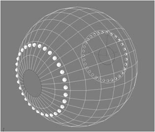
Figure 2-24
25. Switch to the Front view, select the caps, and Extrude the polygons –29.316 or until they intersect in the center. Delete them, select the vertices, and then Weld them.

Figure 2-25

Figure 2-26
26. Select the borders of the tube you made, and Chamfer by 1 and then by 0.3.

Figure 2-27

Figure 2-28
27. Add a Smooth modifier to the stack, click Auto Smooth, and then convert it to an Editable Polygon to collapse the stack.

Figure 2-29
Day 2: Building the Engine Nacelles I


Figure 2-30
3. Hide the eye_pod and switch to the Left view. Convert the tube to an Editable Polygon and change its name to L_nacelle.
4. Switch to Vertex selection mode, select the vertices on the rear of the tube, and scale them down to 70% in all three axes to make an exhaust nozzle.

Figure 2-31
5. Repeat step 4 for the front vertices, but scale them down to 90% in all three axes.
6. Switch to the Left view and select the nine polygons in the middle of the nacelle shown in Figure 2-32, and then Extrude them as a group –2.0 (to recess them).
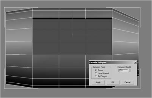
Figure 2-32
7. Select the top left and right polygons in the area you just recessed and under Edit Geometry, click the Tessellate button.
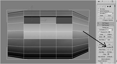
Figure 2-33
 FYI: Tessellate subdivides an object (in this case dividing the selected polygon into four polygons). We are creating jacks for a wiring harness.
8. Select the top-left polygon and bottom-right polygon created by the tessellation.
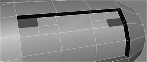
Figure 2-34
9. Click Inset and type 0.5 for the Inset Amount.
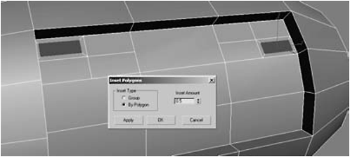
Figure 2-35

Figure 2-36
11. Set the Reference Coordinate system to Local, right-click the Move tool, and type 1.0 in the Offset Local Z axis (to raise the polys and form a crude pyramid).
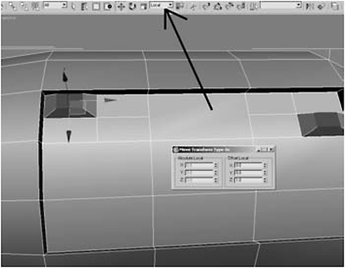
Figure 2-37
Urgent: Step 11 is an important step. Do not skip it! Otherwise, when you move the polygons they ’ll be at an off angle.
12. Hit the Tessellate button twice.
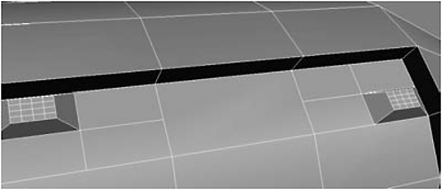
Figure 2-38
FYI: There’s an easier way to do this this. Greeble is an excellent plug-in (max.klanky.com) that automatically creates geometry like on a Star Destroyer or Death Star. Best of all, it’s free! Since I’m teaching you to model without plug-ins, we won’t be using Greeble, but since it’s free I encourage you to download it.
13. Select the polygons you just made through tessellation.

Figure 2-39


Figure 2-40

Figure 2-41
FYI: With regard to what this vent thing you’re building does, Cris Robson (O’Blue) of 3d Palace, a great place for Max tutorials, said it best: “I have no idea what it does, but it looks cool.” When you get a chance, check out some of the really cool (and free!) Max video tutorials available for downloading at www.3d-palace.com.
15. Scale by 50 in the local Y axis.

Figure 2-42
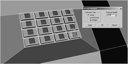
Figure 2-43
17. Under Edit Geometry, click MSmooth.

Figure 2-44
18. Click Grow.
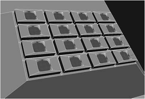
Figure 2-45
19. Extrude 0.05.
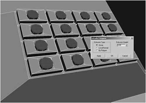
Figure 2-46
Figure 2-47
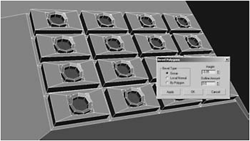
Figure 2-48

Figure 2-49
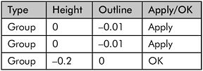

Figure 2-50
22. Hit Render (F9).

Figure 2-51
23. Switch to the Right view and zoom out so you can see both banks of jacks.
24. Under the Create panel, select the Shapes button.
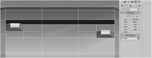
Figure 2-52
25. Click the Line button to create a line spline and create a spline as shown in Figure 2-53. (Each left mouse click creates a vertex, represented by the white cross. When you get to the last cross, click the right mouse button to complete the spline.) Make sure AutoGrid is turned on!
FYI: Don’t get hung up on the exact placement of the vertices. Like polygonal modeling, you can easily move, add, and delete vertices from a spline.
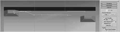
Figure 2-53
26. Switch to Vertex selection mode and select the first vertex.
27. Zoom in close enough that you can see the spline and the individual jacks.
28. Use the Move tool to position the initial vertex inside the jack, as close to dead center as you can.
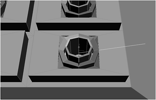
Figure 2-54
29. Use the Move tool to position the next vertex above the initial one, at just under a 90-degree angle.

Figure 2-55

Figure 2-56
 Fire Drill: As you can see from Figure 2-57, this jacks up your spline. In Figures 2-55 and 2-56, you can see the second vertex forms a corner, but this isn’t conducive to smooth wires, so we had to convert it to a smooth bend, and now we have to undo the damage we did in the last step.
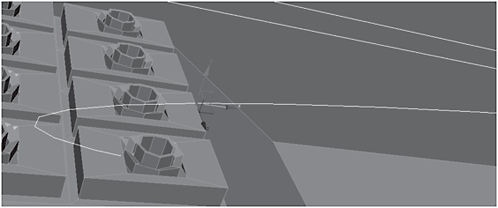
Figure 2-57
31. Drag the Move tool in the X axis (you may also have to move the vertex in the Y axis) until you have a smooth bend in your spline, just above the jack.
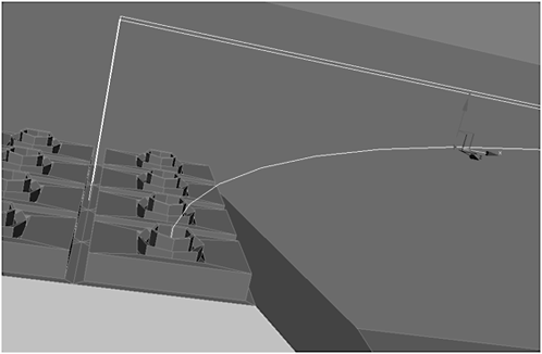
Figure 2-58
32. Convert the next two vertices to Smooth by first selecting them, right-clicking, and then selecting Smooth.
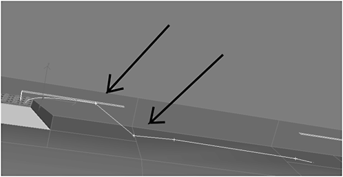
Figure 2-59
Fire Drill: Just because you smoothed vertices doesn’t mean they ’ll be correctly aligned (Figure 2-60). You’ll still need to use the Move tool to adjust the vertices (generally in the Y axis) so they don’t fall beneath the surface of the nacelle, and so the spline resembles a smooth wire (Figure 2-61). If a vertex falls beneath the surface, switch to wireframe mode to find it.

Figure 2-60

Figure 2-61
33. Continue converting vertices to Smooth and moving them until you get to the last vertex.

Figure 2-62
34. At the last vertex, pick a jack (it doesn’t matter which one) and center the vertex inside the jack so the spline is not intersecting with any geometry, especially the jack’s sides.
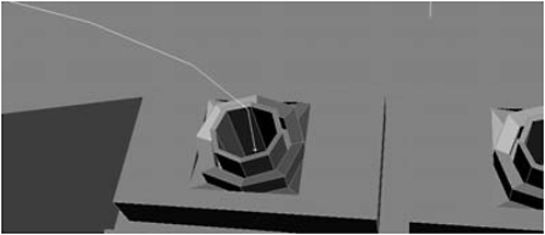
Figure 2-63
FYI: It may be necessary for you to use the Move tool to reposition some of the vertices. I had to move all of my vertices except the first one to get the positioning right. The closer you get two vertices, the sharper the corner.
35. When you’re sure the spline comes straight down into the beginning and end jacks, and none of the vertices intersect the geometry, you’re ready to continue.
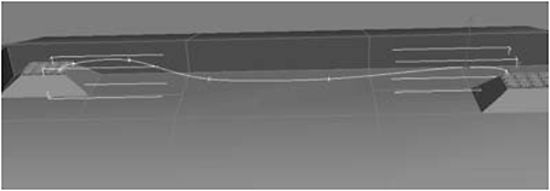
Figure 2-64
36. In the Command panel, find the rollout named Rendering, open it, click Enable In Viewport, and dial down the Radial Thickness and Sides settings until you’re happy (I chose 0.09 and 18).
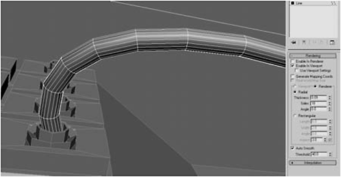
Figure 2-65
 Message: A reasonable person might ask why a designer would leave the wiring exposed. If it’s used for warfare, wouldn’t exposed wires make it vulnerable? The answer is yes, but … it looks cooler this way. If it really annoys you, skip this part.
37. Check again to make sure you don’t have any intersections, then under the Rendering rollout, check Enable In Renderer (it will not render unless checked). Zoom out so you can see the entire wire, and render.
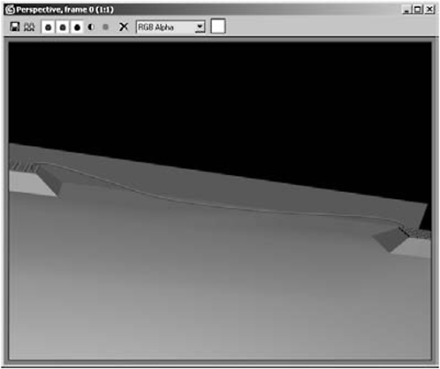
Figure 2-66
38. When you’re satisfied, convert the spline to an Editable Polygon and name it wire01.
Urgent: Don’t skip this step! When we mirror the nacelle, you want the wires to be mirrored as well. Later on, you’ll want to detach them as elements so you can add a different colored material to each wire (or if you prefer, make them all black).
Message: I’ll leave the wiring of the jacks to you. Wire as many or as few as you like, but more wires look more impressive. Try to insert some randomness in your wiring; wiring the same jacks together each time looks boring.
Don’t Forget: You can turn off Enable In Viewport by unchecking the box. I find it easier to work with a spline; periodically Enable In Viewport to make sure the geometry isn’t intersecting.

Figure 2-67

Figure 2-68

Figure 2-69
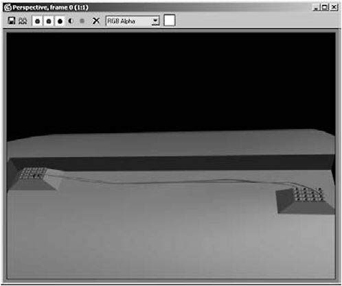
Figure 2-70
Making a “Clay” Render*
A lot of 3D modelers like to create virtual clay models to get a sense of what the model will look like using Global Illumination. Personally, I just think they look cool and that’s reason enough.
1. Add a skylight to your scene: Create panel > Lights > Standard > Skylight.
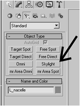
Figure 2-71
2. Use the default settings.
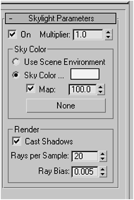
Figure 2-72
3. Position the skylight above your model.

Figure 2-73
4. Press F10 to open the Render Scene dialog, click the Advanced Lighting tab, and under Select Advanced Lighting, select Light Tracer from the pull-down.
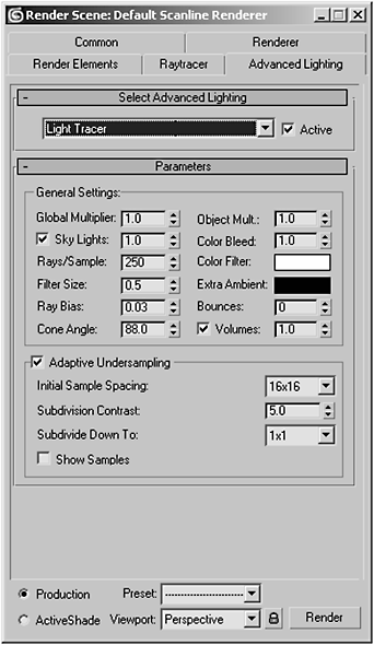
Figure 2-74
5. Close the Render Scene dialog and hit M to open the Material Editor.
6. Select an available slot, name the material Clay, change the Diffuse color to (R:207, G:197, B:178),and be sure the Shader is set to Blinn.
7. If you think you might want to do this in the future with other models, click the Put to Library button to save the material.
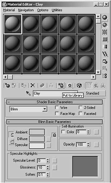
Figure 2-75
8. Apply the material to the selection and render.
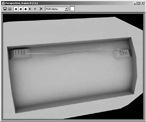
Figure 2-76

Figure 2-77

Figure 2-78

Figure 2-79

Figure 2-80
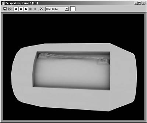
Figure 2-81
* Thanks to Stealth Snake at http://www.oman3d.com/tutorials/3ds/clayrender_stealth/ for teaching me this.
Urgent: Skylight won’t work unless Light Tracer is turned on. However, Light Tracer can dramatically slow rendering! Lowering the Rays/Sample value under Global Settings will speed rendering but lower the quality. If you’d rather use Mental Ray, you don’t need to add the Skylight or Light Tracer. Select Mental Ray as your renderer, apply a Mental Ray material to the object, and under Basic Shaders add an Ambient Occlusion map. Render as normal.
Day 3: Building the Engine Nacelles II
Message: I intentionally didn’t wire every single jack to give the impression the unused jacks might be available for adding custom modules.
1. Select the L_nacelle, switch to Edge selection mode, and select the outer edges surrounding the nacelle’s access port.

Figure 2-82
2. Under Edit Edges, select Chamfer Settings; chamfering subdivides edges and creates additional geometry, which makes an object look smooth.

Figure 2-83

Figure 2-84
4. Set the Chamfer Amount to 0.1 and hit OK.

Figure 2-85
5. Do a test render and see how much the chamfering smoothed the edges.

Figure 2-86

Figure 2-87
6. Switch to Perspective view, Arc Rotate to see the nacelle’s intake nozzle, click one of the inner edges, and click Loop to select them all.

Figure 2-88

Figure 2-89
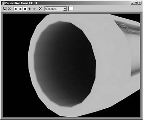
Figure 2-90
8. Repeat the same chamfering process you used for the outer rim of the front nozzle for the outer and inner edges of the rear exhaust nozzle. (I used 0.3 and 0.15 for the rear nozzle values.)

Figure 2-91
9. Zoom in on the junction boxes and polygon-select the sides shown in Figure 2-92 for both boxes.

Figure 2-92
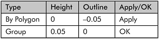
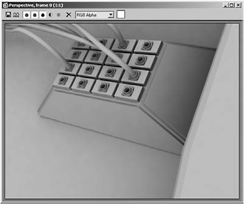
Figure 2-93
11. Select the two side edges of the junction boxes’ bottom faces (be sure to do both sides).

Figure 2-94
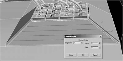
Figure 2-95
Message: If you zoom in on the top and switch to Polygon selection mode, you’ll see it’s really four segments interconnected by five vertices, while the bottom is one continuous edge. We need to make some cuts from the vertices connecting the top edge to the bottom edge so that both are four edges.
13. Make a vertical cut from each top vertex, between each edge, to the bottom edge.

Figure 2-96
14. Do the same for both junction boxes and select the five polys shown in Figure 2-97 for both boxes.
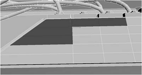
Figure 2-97
15. Inset the polygons by Group by 0.02.
16. Click Bevel Settings:

Figure 2-98
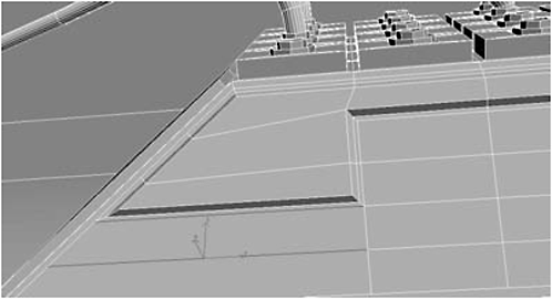
Figure 2-99
18. Select the three polygons for each box as shown in Figure 2-100.

Figure 2-100
19. Group Inset them by 0.02.
20. Click Bevel Settings:

21. Deselect the bottom two polygons on both boxes, leaving the top-right poly selected.

Figure 2-101
22. Hit the Tessellate button twice.
23. Select the polygons shown in Figure 2-102.
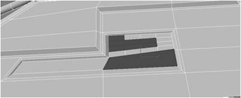
Figure 2-102
24. Click Bevel Settings:

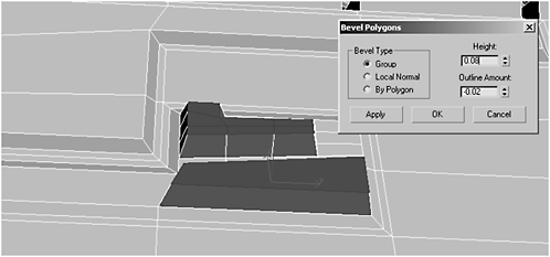
Figure 2-103
25. Select the polygons shown in Figure 2-104 (for both boxes).

Figure 2-104
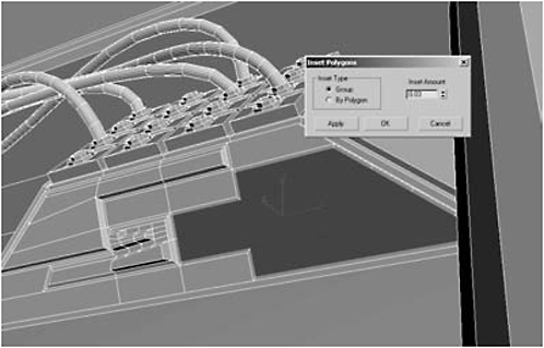
Figure 2-105
28. Delete the polygons, border-select, and then click Cap.

Figure 2-106
Now let’s build some heat sinks …
29. Highlight the middle three polygons.
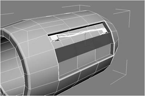
Figure 2-107


Figure 2-108
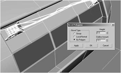
Figure 2-109
31. Edge-select the vertical edges of the inset polygons, but not the edges between.
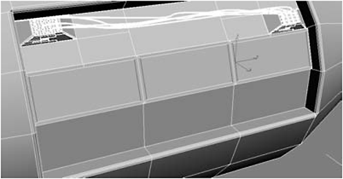
Figure 2-110
32. Click Connect Settings and use 13 Segments.

Figure 2-111
33. Select every other polygon.
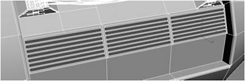
Figure 2-112
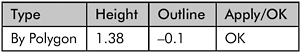

Figure 2-113
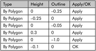
35. Select the bottom left and right polygons, and Inset them By Polygon 0.4.

Figure 2-114
36. Scale them 30 in the Y axis.
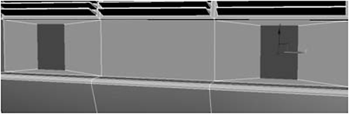
Figure 2-115
37. Select each polygon individually. Move the right poly 3.0 in the Y axis and the left poly –3.0 in the Y axis.

Figure 2-116
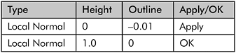
38. Select both polys and Extrude them as Local Normal by 0.01.
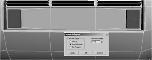
Figure 2-117

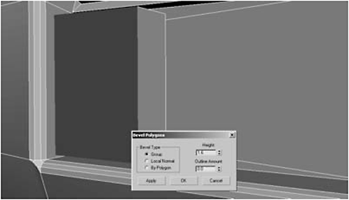
Figure 2-118
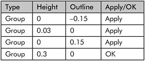

Figure 2-119
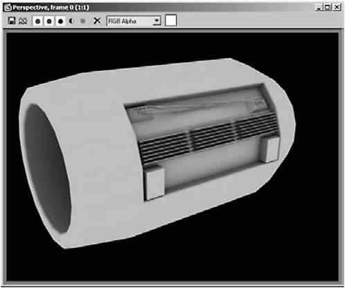
Figure 2-120
41. On the Create panel, select Extended Primitives, click Chamfer Cylinder, turn on AutoGrid, and make a Cylinder on the inside right of the left box.
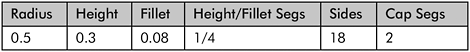
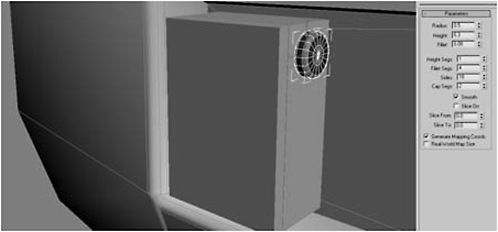
Figure 2-121
42. Convert the chamfer cylinder to an Editable Poly and rename it conduit01.
43. Select one of the edges of the inner cap and click Loop.

Figure 2-122
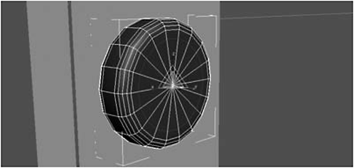
Figure 2-123
45. Highlight the interior polygons and Group Extrude them –0.1.
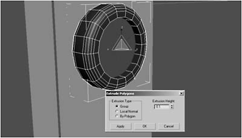
Figure 2-124
46. Inset the polygons as a Group by 0.65.

Figure 2-125

Figure 2-126

Figure 2-127
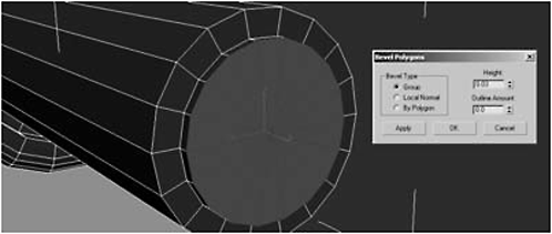
Figure 2-128
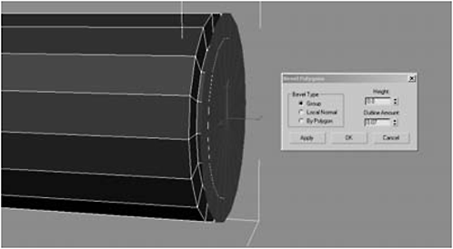
Figure 2-129

Figure 2-130
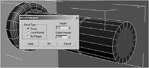
Figure 2-131

Figure 2-132
48. Delete the inward-facing polygons on both sides of the conduit, then switch to the Right view.
49. Mirror a copy of the conduit in the X axis with an Offset of around 11.448 (use whatever offset value causes their borders to touch in the middle).

Figure 2-133
50. Select conduit01, click Attach Settings, and select conduit02 to merge.
51. Switch to Vertex selection mode, select the 36 vertices in the center of the conduit, and click Weld (you make have to alter the weld settings) to complete the merge and reduce the number of middle vertices to 18.
52. Object-select conduit01, Shift-drag in the Y axis, and make three copies.
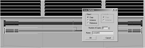
Figure 2-134

Figure 2-135
FYI: As you can tell from Figure 2-135, you may need to move some conduits to fit squarely on the boxes. Feel free to scale their diameter (in the X and Z). It’s not essential they be the same diameter as long as their length remains constant. In fact, varying their diameter may make for a more interesting model.

Figure 2-136
53. Switch to the Perspective view, object-select L_nacelle, and Attach the four conduits.
54. Do a test render.

Figure 2-137
Message: That’s coming along nicely. We need to do a couple more things. For starters, the boxes linking the conduits could use some spicing up. Also, the top near the wiring boxes is kinda bare. We don’t want our nacelle to look “junky,” but we do want it to look like a complicated bit of engineering.
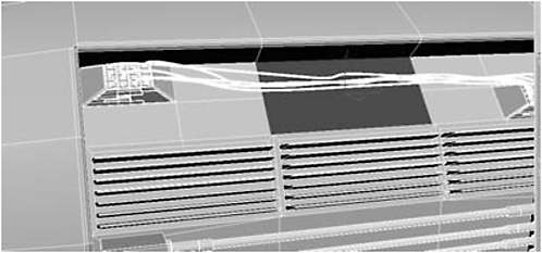
Figure 2-138
56. Click Bevel Settings:

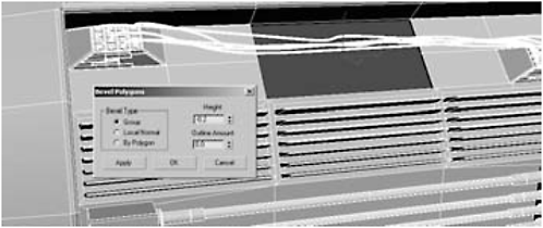
Figure 2-139
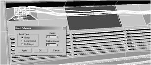
Figure 2-140
FYI: Ideally, we’d Tessellate to make a grate, but extra segments on the sides would give us trouble (see Figure 2-141). Rather than subdividing into smaller rectangles, Max merges the side verts into the center. We don’t want that.

Figure 2-141
57. Use the Cut tool and cut from the segment on the left to the segment on the right, effectively cutting the larger polygon into two smaller ones.
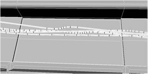
Figure 2-142
58. Select the two polygons and hit the Tessellate button twice.

Figure 2-143
Message: Tessellate now works as it’s supposed to, subdividing the two polygons into 32. But now the polys are rectangles, and we want to make a more interesting grate than that. We need square geometry to use MSmooth.
59. Select the 40 vertical edges. Use Arc Rotate to keep from selecting the wires.
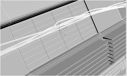
Figure 2-144

Figure 2-145
61. Change the Chamfer Amount to 0.31, and click OK.
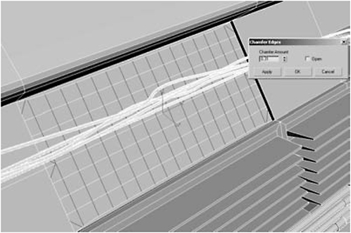
Figure 2-146
62. Select the middle polygons, being careful not to select any of the wires or any border polygons that ended up with angled segments, and then click Bevel Settings.
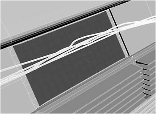
Figure 2-147
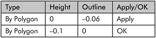

Figure 2-148

Figure 2-149
63. Click MSmooth (the button, not the modifier) and use 1.0 for the Smoothness.

Figure 2-150

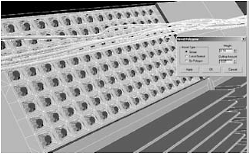
Figure 2-151

Figure 2-152
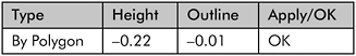

Figure 2-153
Figure 2-154
Day 4: Building the Engine Nacelles III — Pipes
1. Select the three polygons shown in Figure 2-155.

Figure 2-155

Figure 2-156
3. Hit Tessellate once.
4. Inset By Polygon 0.1.
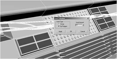
Figure 2-157
5. Scale the polygons 49 in the Y axis to square them off.

Figure 2-158
6. Extrude by Local Normal –0.05.

Figure 2-159
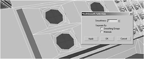
Figure 2-160
8. Click Grow and then Extrude by Local Normal –0.05.

Figure 2-161
9. Group Inset by 0.03.
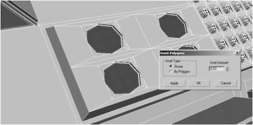
Figure 2-162
10. Group Extrude by 0.2.
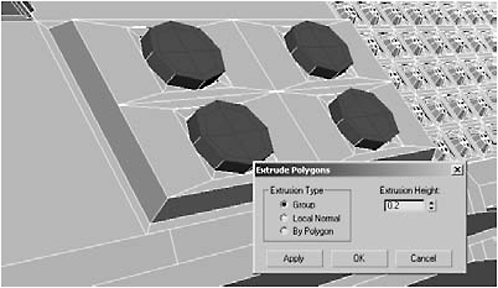
Figure 2-163

Figure 2-164
12. Group Extrude by 0.1.
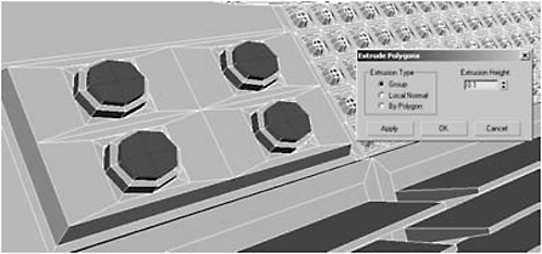
Figure 2-165
13. Delete the polygons, border-select each of them, and then Cap them; this reduces the number of polygons from four to one.
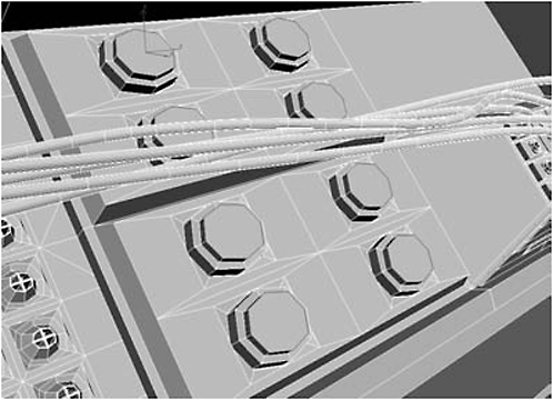
Figure 2-166
14. Select the polygon shown in Figure 2-167.

Figure 2-167

Figure 2-168
17. Turn on Angle Snap and rotate the clone 30 degrees in the Z axis.

Figure 2-169
18. Click Hinge From Edge and use the edge shown in Figure 2-170.
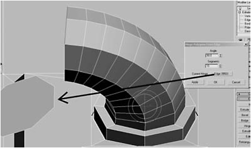
Figure 2-170
19. Delete the cloned element since we don’t need it anymore.

Figure 2-171
21. Shift-drag to Clone To Element in the X axis by 0.2.
22. Switch between the Top, Right, and Perspective views, repositioning the polygon until it is at a 90-degree angle to the pipe, facing upward toward the junction box.
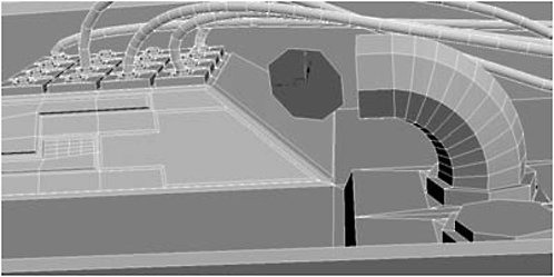
Figure 2-172
FYI: It may help you (it helps me) to border-select the clone and cap its rear, making a two-sided polygon, so when you rotate around the element it doesn’t disappear.
Message: You might ask why I didn’t just use a spline. Splines result in a smooth look more suited to wires. I wanted a segmented pipe. However, when your pipe starts at a strange angle and then curves, it can be challenging. You may have to play around with positioning until you get a segment you’re happy with.

Figure 2-173
23. Move the element in the Z axis into its final position (see Figure 2-174), between the pipe and the junction box.

Figure 2-174
24. Do a Hinge From Edge of 90 degrees using the edge shown in Figure 2-174 with a Segments setting of 10.

Figure 2-175
25. Delete the cloned element, as we no longer need it. Remember to delete both sides.

Figure 2-176
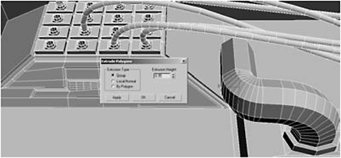
Figure 2-177
27. Shift-drag in the Z axis to Clone To Element and then flip the polygon so it’s facing back toward the pipe.

Figure 2-178
28. Switch to the Top view.
Figure 2-179
29. Rotate the polygon 5 degrees in the Y axis until it is correctly angled.

Figure 2-180
30. Hinge From Edge 90 degrees using the edge shown in Figure 2-181.

Figure 2-181
31. Extrude 0.73 (or until the polygon intersects with the surface of the junction box).

Figure 2-182
32. Zoom out in the Perspective view and do a render.

Figure 2-183
33. Select the polygon shown in Figure 2-184.
Figure 2-184
34. Shift-drag up in the Z axis to Clone To Element, and continue moving it up in the Z until it is even with the surface of the pipe fixture.
Figure 2-185
35. Select the polygon on the top of the pipe fitting and Hinge From Edge, using the left edge of the cloned element.
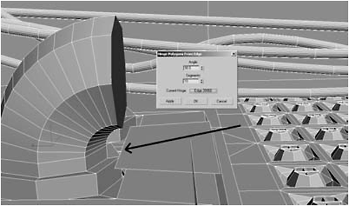
Figure 2-186
36. Select the cloned element and move it across the nacelle to the pipe fittings on the rear.

Figure 2-187

Figure 2-188
38. Delete the cloned element and select the facing surfaces on both pipes.
39. Group Extrude the polygons by 5.68.

Figure 2-189
40. Click Bevel Settings:

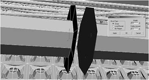
Figure 2-190

Figure 2-191
41. Delete the facing polygons, switch to Vertex selection mode, and weld the overlapping vertices.
42. Select the polygon at the left base of the lower-left pipe at the left side of the nacelle.
Figure 2-192
43. Shift-drag the polygon (Z axis) to Clone To Element, aligning with the top of the pipe fitting.

Figure 2-193
44. Hinge From Edge 90 degrees using the right edge of the cloned element as the hinge.
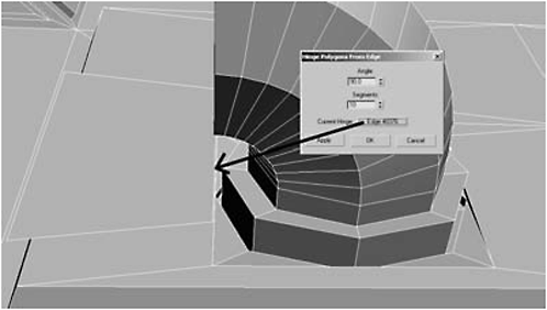
Figure 2-194
45. Move the cloned element around 1.7 in the local Y axis.
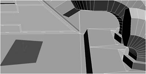
Figure 2-195

Figure 2-196
47. Switch to the Right view, select the cloned element, and rotate it 90 degrees in the X axis.

Figure 2-197
48. Move the cloned element until it’s aligned with the pipe edge facing the junction box.
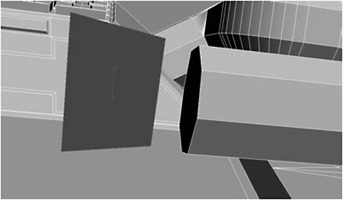
Figure 2-198
49. Select the polygon at the end of the pipe and Hinge From Edge 90 degrees.
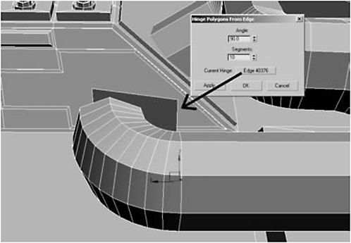
Figure 2-199

Figure 2-200
51. Extrude by 0.05 and then rotate the polygon –5 in the Y axis.

Figure 2-201
52. Repeat step 51 ten more times.

Figure 2-202

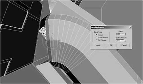
Figure 2-203
54. Group Extrude 0.4.
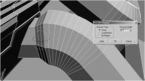
Figure 2-204
55. Select the polygons shown in Figure 2-205 and Group Extrude them by 0.8.

Figure 2-205
56. Select the polygon at the base to the right of the left most pipe.
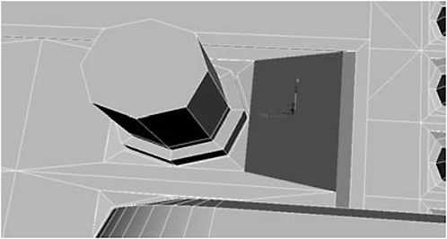
Figure 2-206
58. Align the clone with the top of the pipe and Hinge From Edge 90 degrees.

Figure 2-207
59. Delete the cloned element, Group Extrude the polygon by 4.0, and then switch to the Right view.

Figure 2-208

Figure 2-209
61. Repeat step 60 four times.

Figure 2-210
62. Extrude by 0.1 and then rotate 10 in the Y axis.
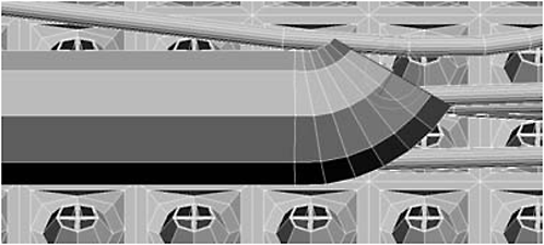
Figure 2-211
63. Repeat step 62 three times.

Figure 2-212
64. Select the polygon at the base of the pipe fitting on the right side.
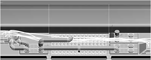
Figure 2-213
65. Clone To Element in the local Z axis and move it so it is even with the top of the pipe fitting.

Figure 2-214
66. Select the polygon atop the pipe fitting and Hinge From Edge 90 degrees.

Figure 2-215
67. Extrude the polygon by 6.98 and then delete the cloned element.
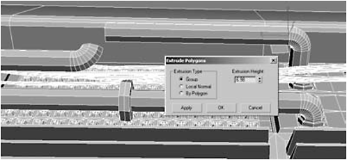
Figure 2-216
68. Switch to the Right view, select the facing polygon of the pipe fitting, and zoom in (z).
69. Extrude by 0.1 and rotate 10 degrees in the local Y axis.
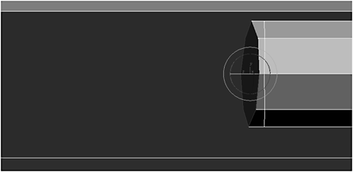
Figure 2-217
70. Repeat step 69 three more times.
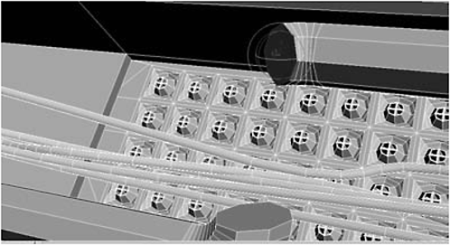
Figure 2-218
71. Extrude by 0.1 and rotate 10 degrees in the local X axis.
72. Repeat step 71 four more times.

Figure 2-219
73. Extrude by 0.1 and then rotate 10 degrees in the X axis and –10 degrees in the Y axis.
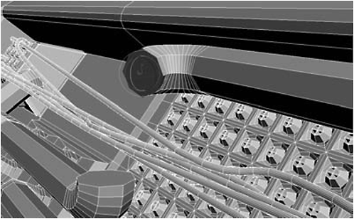
Figure 2-220
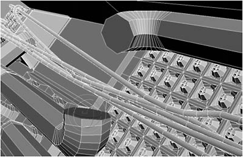
Figure 2-221
76. Extrude by 0.1 and then rotate 10 degrees in the local X axis.
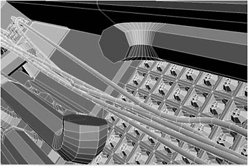
Figure 2-222
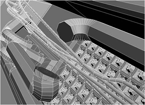
Figure 2-223
78. Extrude by 0.1 and then rotate 10 degrees in the Y axis.
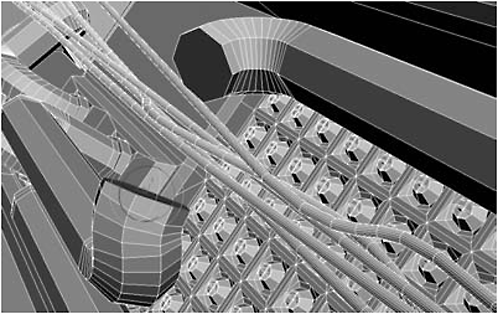
Figure 2-224
79. Repeat step 78 three times.
80. Extrude by 0.1 three times.
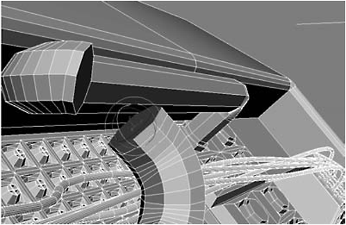
Figure 2-225
81. Extrude 0.1 and then rotate 10 degrees in the local X axis.

Figure 2-226
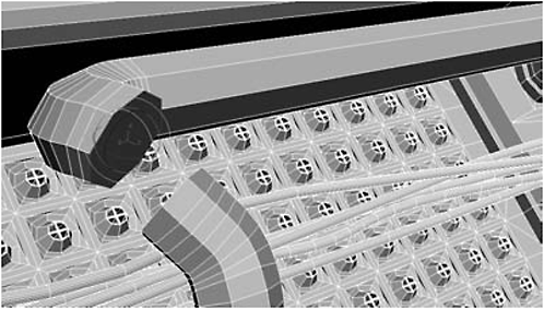
Figure 2-227
83. Extrude it by 0.1, then rotate it –10 degrees in the Y axis and 5 in the Z axis.

Figure 2-228
84. Extrude it by 0.1 and the rotate it by 5 degrees in the X axis.
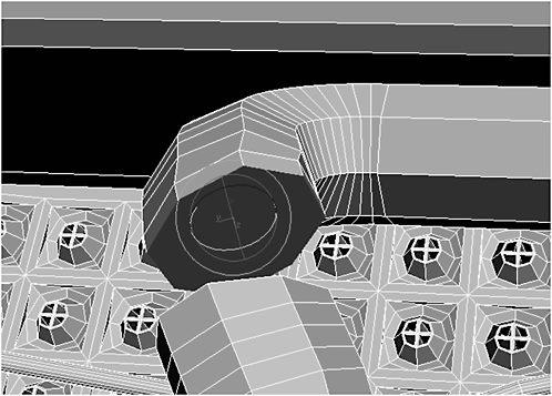
Figure 2-229
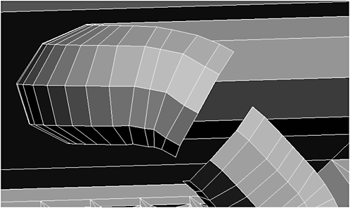
Figure 2-230
86. Click an edge on each pipe and click Bridge.
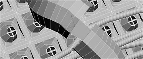
Figure 2-231
FYI: You may want to move vertices before bridging to make your pipe smoother looking.

Figure 2-232
Message: I intentionally didn’t straighten every vertex to make perfect contours; I wanted an irregular look. If you prefer, move the vertices until the contours are smooth.
88. Select the polygon at the base of the pipe fitting on the rightmost collection of fittings.
Figure 2-233
89. Clone To Element and move in the local Z axis to align to the top of the lower-right pipe fitting.

Figure 2-234
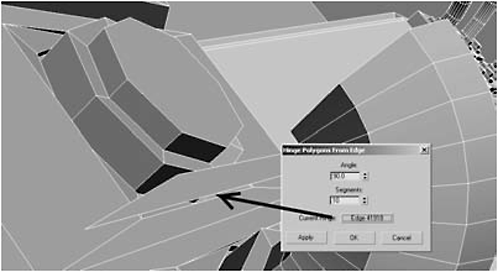
Figure 2-235
91. Move the clone 2.196 in the local X axis so it is beneath the upper-rightmost pipe fitting.

Figure 2-236
92. Select the polygon atop the upper-rightmost pipe fitting, Hinge From Edge 90 degrees, then delete the cloned element.

Figure 2-237
93. Select the facing polygons on both pipes and Group Extrude them until they meet (around 1.16).

Figure 2-238
94. Delete the inward-facing polygons on both pipes.
95. To fix the problem of wires intersecting pipes, select the four polygons on the top of the pipe (two on each side of the connection).

Figure 2-239
96. Click Grow until the entire pipe is highlighted except for a single set of polygons at the base of each fitting.
Figure 2-240
97. Right-click the Select and Move tool.
98. In the Transform Type-In dialog, set the Offset World X to 0.80 and the Z to 0.73.

Figure 2-241
99. Switch to Vertex selection mode, highlight the vertices along the middle seam, and Weld them.

Figure 2-242
Message: At this point, I’m going to move on. Add as many pipes, wires, and hoses as you want. The more you have, the more complicated and techy your bot will look.
100. Select the polygon atop the lower-left junction box.
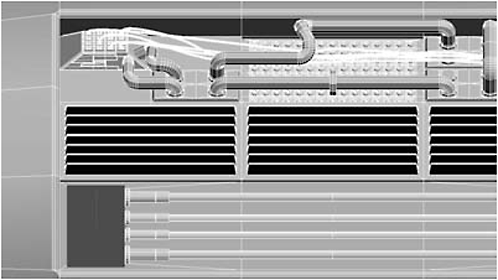
Figure 2-243
101. Zoom in on it, then go to the Create panel, select Sphere, turn on AutoGrid, and create a hemisphere in the upper-left corner of the junction box with a Radius of 0.2 and 32 Segments.
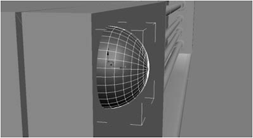
Figure 2-244
102. Switch to the Perspective view to make sure that the sphere is seated just below the surface of the junction box (see Figure 2-244), choose Convert to Editable Polygon, and then delete the sphere’s polygons that are lying beneath the surface of the junction box.
103. Switch back to object mode and Shift-drag to clone the sphere (make seven copies so you have one for each junction box corner) and then position one rivet in each junction box corner with the Move tool.
Message: Because the junction boxes are seated at an angle, use the Perspective view to double-check that all the rivets are seated below the surface of the junction box.

Figure 2-245
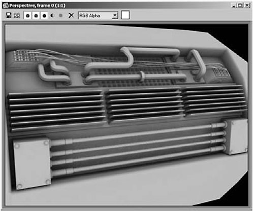
Figure 2-246
Day 5: Detailing the Nacelle
1. Select the nacelle’s rear polygons, activate Slice Plane, and move the slice plane approximately 16 in the X axis.
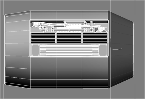
Figure 2-247
2. Click the Slice button and then turn off Slice Plane.
3. Select one of the segments created using Slice Plane and click Loop.

Figure 2-248

Figure 2-249
5. Highlight the new polygons you made with the chamfer.
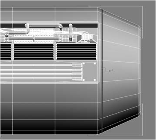
Figure 2-250
FYI: We extruded by “Local Normals” rather than by Group because you want the polys to extrude inward around the nozzle, creating a groove where the nozzle connects to the nacelle.
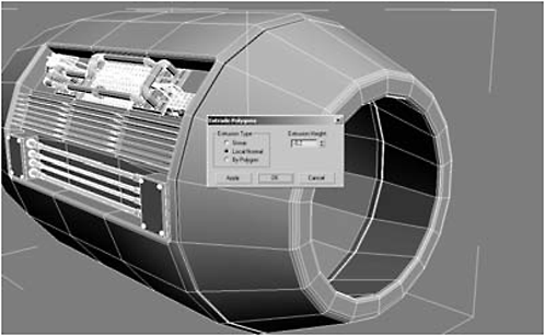
Figure 2-251
7. Select the 18 polygons shown in Figure 2-252, exercising extreme care not to select the polygons on the outer nozzle or the polygons inside the nozzle.

Figure 2-252
Message: These are air brakes. If I were doing this for a film, I’d detach the panels and put a hydraulic system below them.

Figure 2-253

Figure 2-254
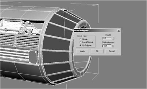
Figure 2-255

Figure 2-256

Figure 2-257

Figure 2-258
9. Switch to the Right view, select the polygons shown in Figure 2-259, click Slice Plane, and move the slice plane approximately –16 in the X axis.
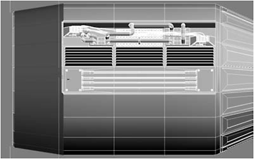
Figure 2-259
10. Click Slice and then turn off Slice Plane.
11. Switch to Edge selection mode and loop-select the slice you just made, as you did in step 3.
12. Chamfer the edge by 0.12, as in step 4, and select the new polys you made, as in step 5.
Figure 2-260
13. Extrude by Local Normals –0.2.
Figure 2-261
14. Highlight the polygons shown in Figure 2-262:

Figure 2-262

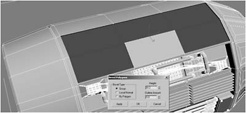
Figure 2-263

Figure 2-264

Figure 2-265
Message: A test render shows what we’ve been doing: creating a mechanic’s access panel for working on the interior components. We’re going to use the same technique to trim out the rest of the nacelle.
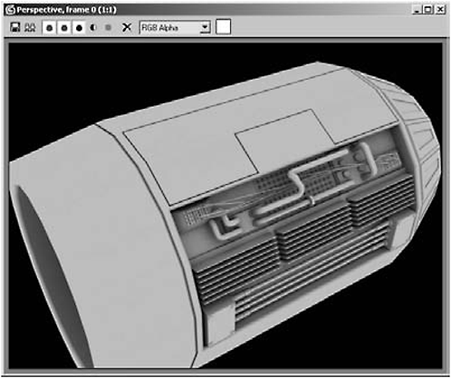
Figure 2-266
16. Highlight the polygons shown in Figure 2-267.
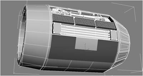
Figure 2-267
17. Repeat the Bevels from step 15.
18. Select the nine polygons on the bottom of the nacelle as shown in Figure 2-268.

Figure 2-268
Day 6: Building the Rotors
1. Switch to the Front view and, using AutoGrid, create a Cone primitive in the middle of the nacelle’s air intake with the following settings:
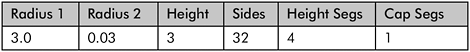

Figure 2-269
2. Switch to the Right view and move the cone into its proper position, just inside the nacelle’s air intake (around –83 in the X axis).
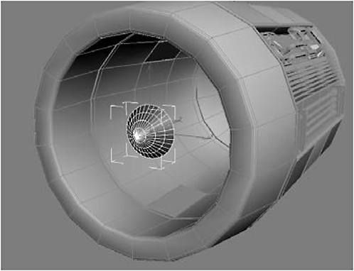
Figure 2-270
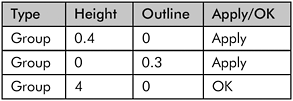

Figure 2-271
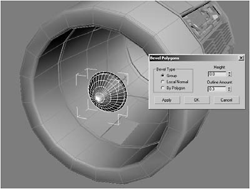
Figure 2-272

Figure 2-273
4. Select and delete the rear-facing polygons.

Figure 2-274
5. Select the 32 polygons at the rear of the rotor:
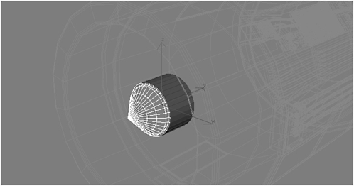
Figure 2-275

Figure 2-276
7. Switch to the Right view, turn on Vertex selection mode, marquee-select the two rear vertices of each blade (96 total), and rotate them 30 degrees in X.
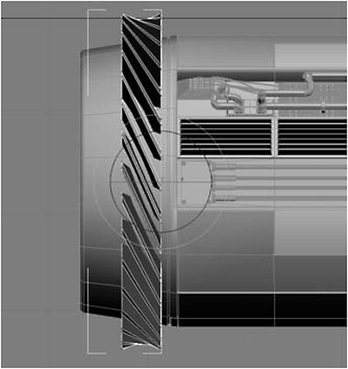
Figure 2-277
8. Switch to Polygon selection mode (the tips of the blades should still be selected), go to the Front view, and scale the blades down to 30%.

Figure 2-278

Figure 2-279
9. Switch to Object mode and the Perspective view, then scale the entire blade-rotor assembly down to 66 in the X and Zaxes (or until the blades do not intersect the nacelle).

Figure 2-280
10. Apply the Clay material to the rotor assembly, rename it rotor assembly, and do a test render. If you prefer a rounder look, you can always use NURMS with three iterations, as shown in Figure 2-282.

Figure 2-281
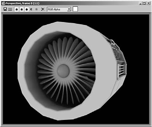
Figure 2-282
11. Switch to the Back view and, using AutoGrid, create a Cone in the rear nozzle and adjust its values to match those in the following table.

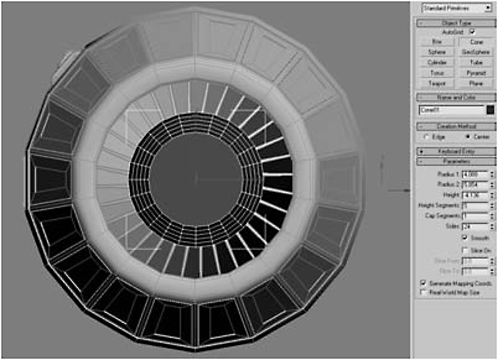
Figure 2-283
12. Convert the cone to an Editable Polygon and select the 18 segments in the center of the tip.

Figure 2-284
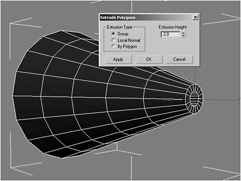
Figure 2-285
14. Select the rear 72 polygons, but not the rear-facing one nor the 18 inside the cone.

Figure 2-286
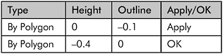

Figure 2-287
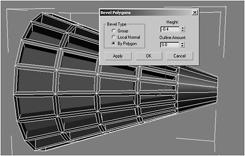
Figure 2-288
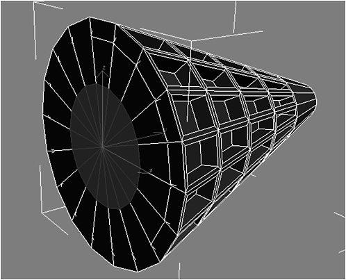
Figure 2-289


Figure 2-290

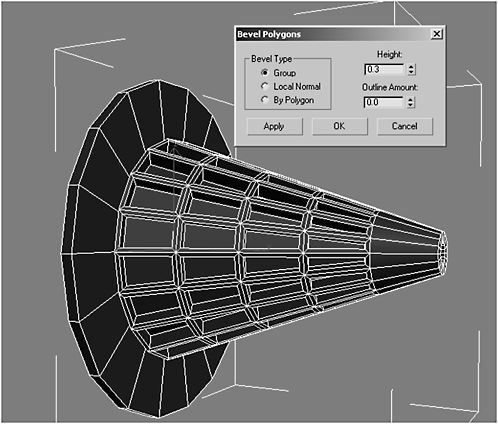
Figure 2-291
17. Move the exhaust cone into position in the nacelle exhaust nozzle.
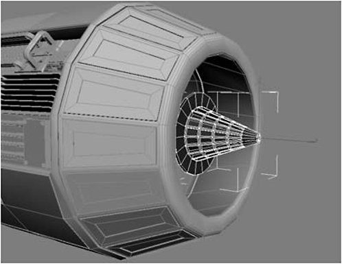
Figure 2-292
18. Switch back to Polygon selection mode and adjust the bevel settings until the cone just intersects the exhaust nozzle.


Figure 2-293
19. Select the 36 polygons behind the front cone, but be sure you leave a row of polygons unselected:

Figure 2-294
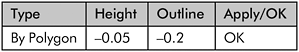
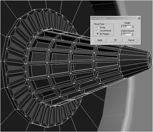
Figure 2-295
21. Extrude By Polygon –5.0.
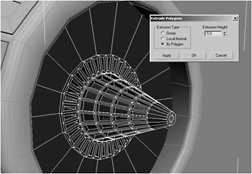
Figure 2-296
Figure 2-297
23. Click Bevel Settings:


Figure 2-298
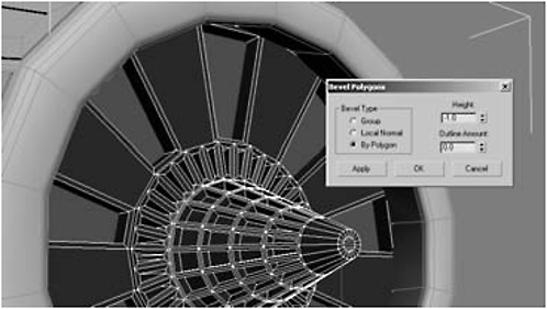
Figure 2-299
24. Select one of the polygons and zoom in until you can see the inside edge.
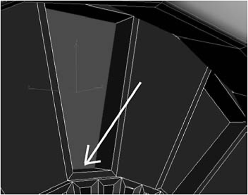
Figure 2-300

Figure 2-301
26. Repeat step 25 for the remaining eight polygons that are recessed.

Figure 2-302
Figure 2-303
28. Click Bevel Settings:
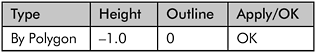
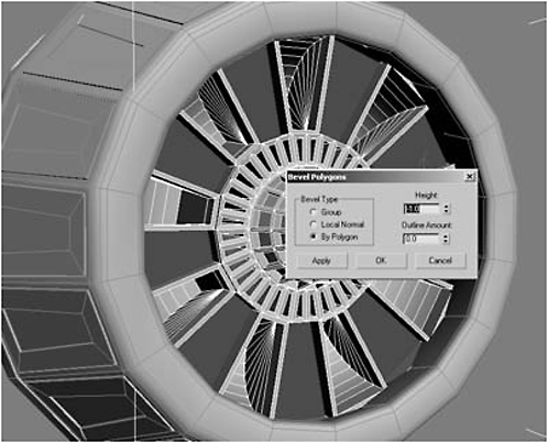
Figure 2-304
29. In one of the recesses you’ve made, create a Box using AutoGrid with these settings:

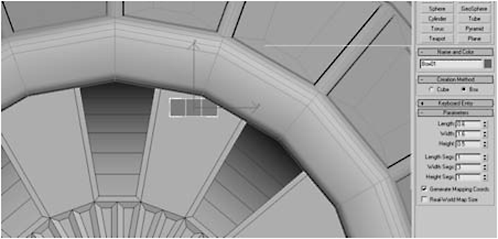
Figure 2-305
30. Switch to Perspective view, Arc Rotate until you can see the part of the box that faces the center cone, and use AutoGrid to create a Cylinder to the left of the leftmost segment.


Figure 2-306
31. Add a Bend modifier to the cylinder’s stack, using a Bend Angle of 57.
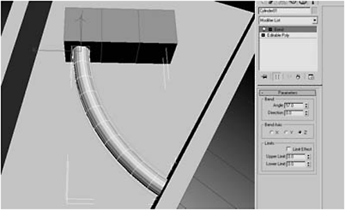
Figure 2-307
32. Add a Smooth modifier to the cylinder’s stack, then right-click and choose Convert to Editable Polygon.
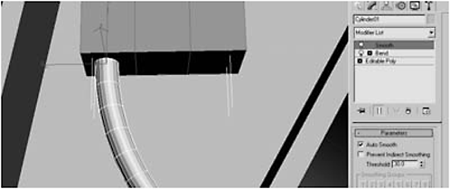
Figure 2-308
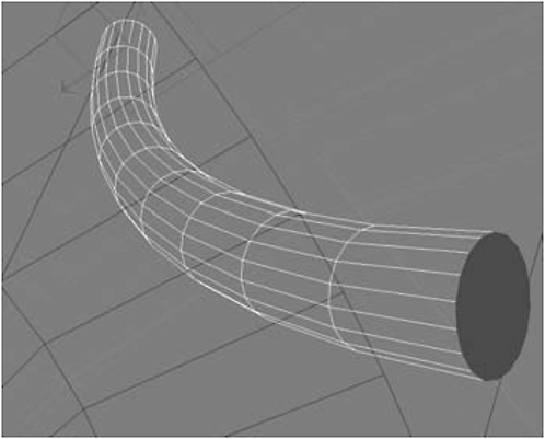
Figure 2-309
34. Using AutoGrid, create a Torus in the recessed area closest to the nozzle and then convert it to an Editable Polygon.


Figure 2-310
35. Using AutoGrid, create a Sphere centered inside the torus (you’ll have to move it up in the Local Z axis, as you’re looking for more of an egg in an egg cup than a rivet) with a Radius of 0.66 and 32 Segments. Then convert it to an Editable Polygon.
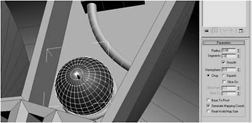
Figure 2-311
36. Highlight the top two center rings of polygons (64 total) and Group Extrude them by 0.02.

Figure 2-312
37. Click Shrink (to shrink the selection down to the centermost 32 polys), Group Extrude them –0.1, and then delete them.

Figure 2-313
38. Border-select the border you created by deleting the center polygons, click Create Shape From Selection, and name it compressor_seal.
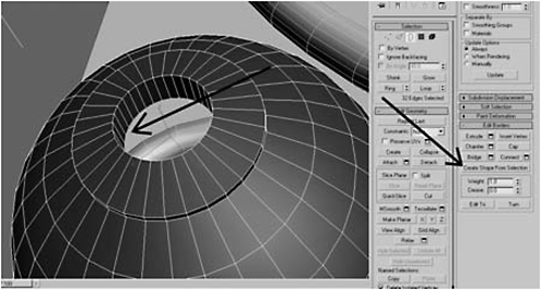
Figure 2-314
39. Open the Rendering rollout and choose the settings in the following table, then move the seal up (in the Local Z axis) to the top of the opening and convert it to an Editable Polygon.

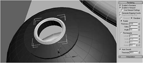
Figure 2-315
40. Using AutoGrid, create a Cylinder in the center of the seal (it’s likely you’ll need to switch between the Back and Perspective views to get it seated properly), and then raise it in the Local Z axis:

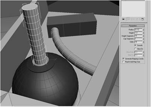
Figure 2-316
41. Convert the cylinder to an Editable Polygon and add a Bend modifier to the stack with an Angle of 90. Use a Direction of –65.5 to turn the bend to face the box you made instep 29.
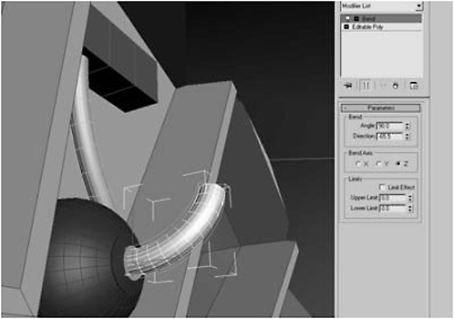
Figure 2-317
42. Click the cap polygon facing the box, Group Extrude it by 1.4, and hit Apply.
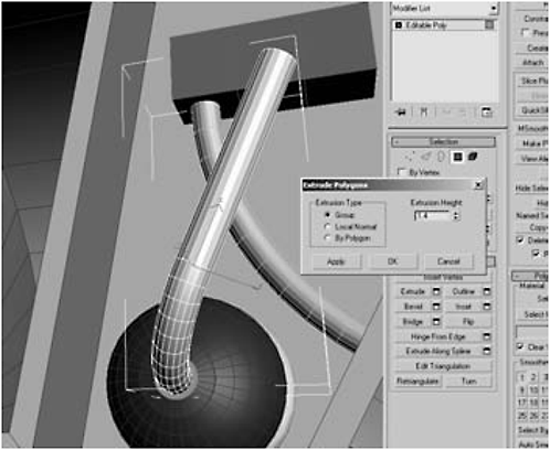
Figure 2-318
43. Reset Extrude to 0.08 and click Apply 14 times and then click OK (you should have 15 extrusions of 0.08).
FYI: When using the Bend modifier, more segments make smoother bends.
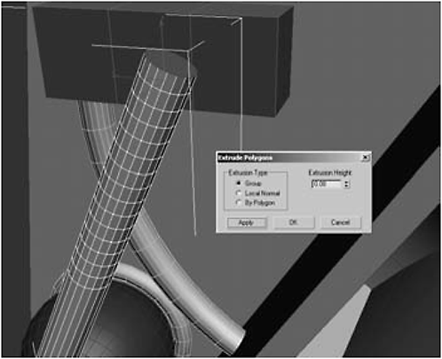
Figure 2-319
44. Click Grow until all the segments have been selected and then click Detach to detach it as an object (don’t bother giving it a name as it’s not going to be around long).
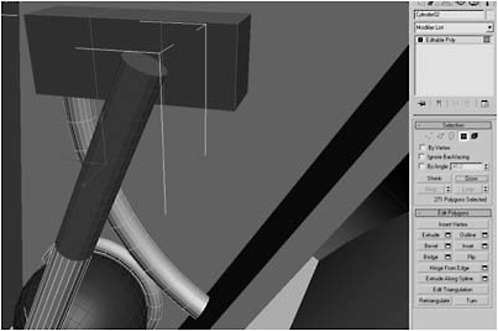
Figure 2-320
45. Hit the H key, select the object you just created, convert it to an Editable Polygon, click the Hierarchy tab, click Affect Pivot Only, and click Center to Object.

Figure 2-321
FYI: Because this new object was once part of the compressor_tube, its pivot point is the same. You have to move the new object’s pivot so the Bend modifier will give you the effect you want.
46. Move the pivot until it is at the edge of the objects, where it connects to the original tube.

Figure 2-322
47. Apply a Bend modifier to the new object’s stack with these settings:

FYI: The Limit Effect and Upper Limit controls do what you think they do. The Bend modifier uniformly affects the object. Sometimes, as in this case, you want the pipe to either start or end straight and bend at the opposite end. Limiting the effect limits the Bend modifier’s influence at the ends. If you want to make a U-shaped bend you enter values for both the Upper and Lower Limit settings.

Figure 2-323
48. Convert the new object to an Editable Polygon to collapse the stack. Select the original pipe, which exits the sphere, click Attach List, and attach the object to it so they once again form a single object.
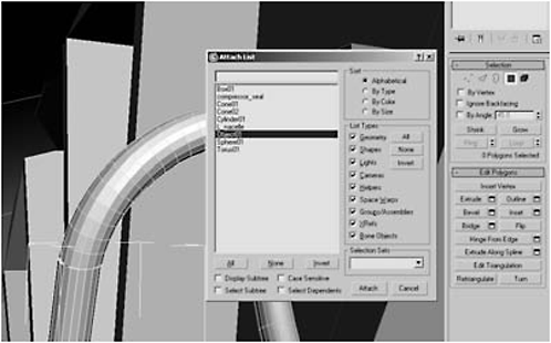
Figure 2-324
49. Switch to Vertex selection mode, select the 36 vertices that form a seam, and click Weld Vertices, adjusting the Weld Threshold until the number of vertices is lowered by 18 (in my case, it went from 504 to 486).

Figure 2-325
50. Select the cap polygon that faces the box, and Extrude it until it just meets the surface of the box (mine is 0.32).
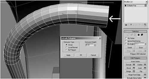
Figure 2-326
51. Delete the polygon facing the box. Border-select the border created by the deletion, click Create Shape From Selection, and call the new shape compressor_seal. Then hit H, select compressor_seal from the list, and apply these settings:

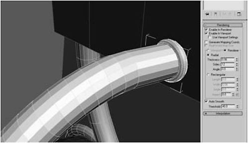
Figure 2-327
52. Convert the seal to an Editable Polygon, go to the Hierarchy tab, click Affect Pivot Only and Center to Object, and use the Move and Rotate tools to make the seal look evenly placed.

Figure 2-328
53. With the seal still selected, click Attach List, and click all the components making up the compressor system.

Figure 2-329
54. Name the new object compressor.
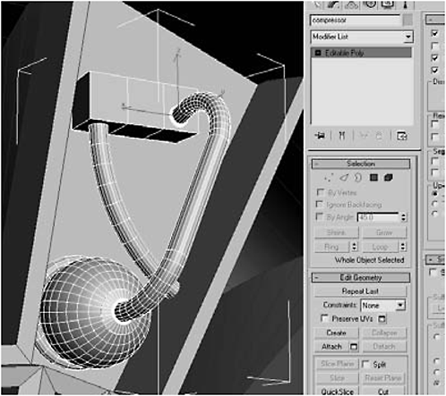
Figure 2-330
55. Switch to the Back view, zoom out so you can see the entire exhaust nozzle, click the Hierarchy tab, click Affect Pivot Only, and move the compressor’s pivot to the center of the exhaust nozzle.
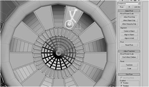
Figure 2-331
56. Shift-rotate (around 40 degrees in Z) until you have a compressor clone positioned in the next recess, select clone, and enter 8 for Number of Copies.
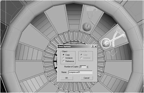
Figure 2-332
57. Object-select the exhaust cone, click Attach List, and select all the compressor clones. Click OK.
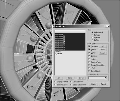
Figure 2-333
58. Switch to the Perspective view and do a test render.

Figure 2-334
Message: Don’t worry that you can’t see all the compressor components; their position puts them into shadow. Once you add additional lights or animate the model, you’ll see them.
Day 7: Building the Wing
1. In the Top view, create a Box adjacent to the nacelle.


Figure 2-335
2. Convert the box to an Editable Polygon and rename it wing.
3. Click the Hierarchy tab, click Affect Pivot Only, and move the pivot in the X axis to the edge opposite the nacelle.
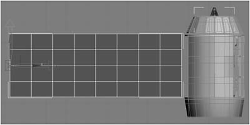
Figure 2-336

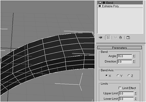
Figure 2-337
5. Hide the wing and switch to the Front view.
6. With your cursor in the center of the nacelle, using AutoGrid, create a Tube that envelopes the nacelle like a glove.


Figure 2-338
7. We don’t want to cover up all that nice pipe work we worked so hard to make, so check Slice On under the tube’s Parameters rollout, set Slice From to –250 and Slice To to–6.0, and rename it wing_ brace.

Figure 2-339

Figure 2-340
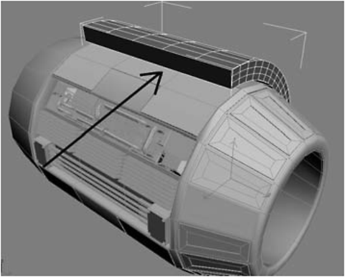
Figure 2-341
Fire Drill: One problem with Slice — at least for me — is your segments don’t carry over to the sliced edge. There must be a reason it does this, but it means we’re going to have to do some additional cuts and slices.
9. Convert wing_brace into an Editable Polygon and use the Cut or Slice tool — your preference — to create two horizontal and four vertical cuts so that the sliced edge is consistent with the rest of the object.

Figure 2-342
FYI: I found it to be helpful to temporarily hide the nacelle when making these cuts. Be sure you cut both the top and bottom edges!
10. Currently, our brace is covering our access port, so switch to the Front view and use the Rotate Transform Type-In dialog to rotate the wing_brace 15 in the Z axis.
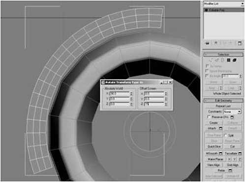
Figure 2-343
11. Switch to the Top view, use the Scale tool to scale the brace down to 96 in the Y axis, and center the brace.
12. Select the bottom two rows of polygons on the edge of the brace, on both the top and the bottom edges.
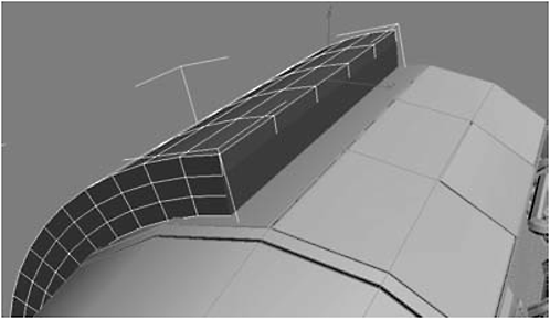
Figure 2-344
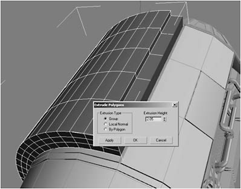
Figure 2-345
14. Select the five polygons on the top surface of your extrusion (do this on the top and bottom).
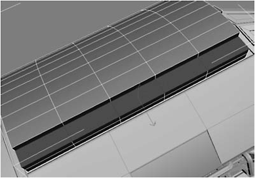
Figure 2-346
15. Click Bevel Settings:

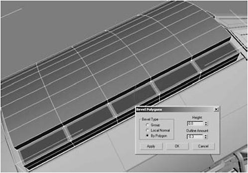
Figure 2-347
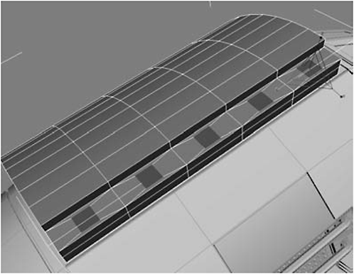
Figure 2-348
17. Group Extrude them –0.01.

Figure 2-349
18. Under Edit Geometry, click MSmooth.
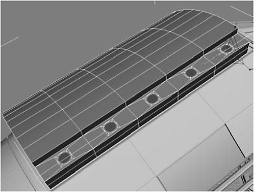
Figure 2-350
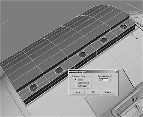
Figure 2-351

Figure 2-352

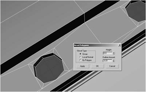
Figure 2-353

Figure 2-354

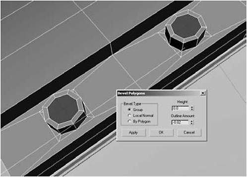
Figure 2-355

Figure 2-356
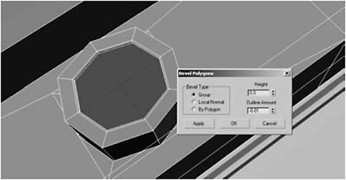
Figure 2-357
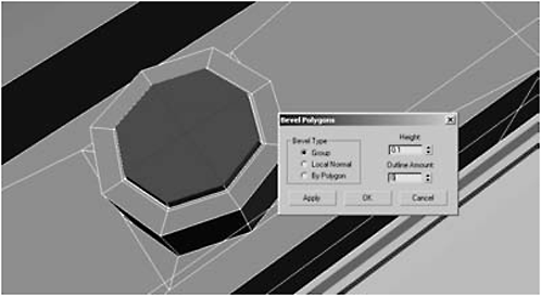
Figure 2-358

Figure 2-359
22. Select the nacelle and then Select and Link it to the wing_brace.
23. Switch to Edge selection mode and select all the sharp outer edges (there should be 122 in all); you may want to switch to wireframe to make it easier.
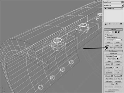
Figure 2-360
24. Chamfer the edges 0.06 and hit Apply, then Chamfer the edges 0.02 and hit Apply again.
25. Do a test render.
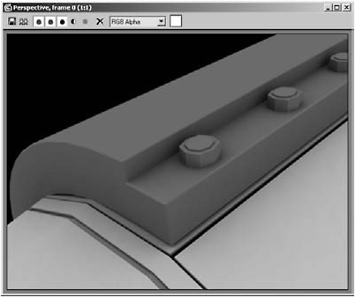
Figure 2-361
26. Unhide the wing.
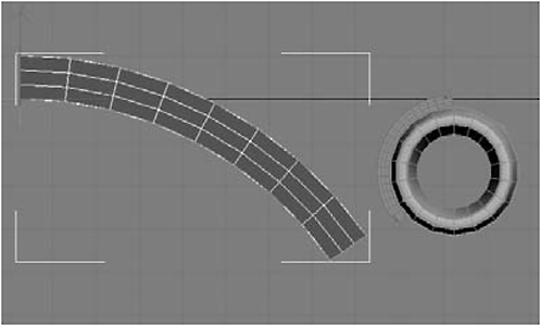
Figure 2-362

Figure 2-363
28. Move the wing 13 in the X axis.

Figure 2-364

Figure 2-365
Message: Look at the wing from the Top view. It’s too wide for the wing_brace. We could scale the wing, but we really want it wider at the chassis and narrower at the nacelle.
30. Right-click the wing, convert it to an Editable Polygon to collapse the stack, and then add an FFD 2x2x2 modifier to the stack.

Figure 2-366
FYI: FFD stands for free form deformation. FFD modifiers are used in animation. They create a lattice around the underlying geometry, allowing you to make significant changes to the overall shape by manipulating a few control points rather than dozens of vertices. There are three flavors of FFDs: 2x2x2, 3x3x3, and 4x4x4. The values refer to the number of control points (see Figure 2-367). The higher the number of control points, the tighter the control over the underlying geometry.

Figure 2-367
31. Click on FFD in the stack to open up the controls and select Acti vate All under Control Points.
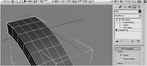
Figure 2-368
32. Select the four control points closest to the nacelle and scale them down to 45 in the X axis.

Figure 2-369
33. Arc Rotate so you can see where the wing meets the brace. Notice that the wing is not evenly spaced on the brace.
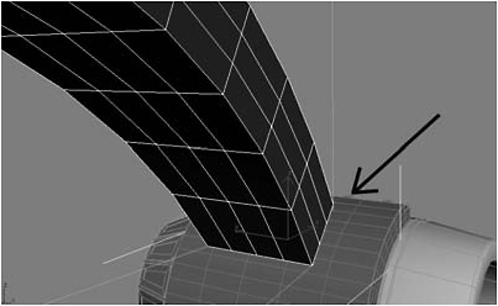
Figure 2-370
34. Right-click, choose Convert to Editable Polygon, and move the wing –1.482 in the Y axis, or until it is evenly positioned on the brace.

Figure 2-371
35. Switch to wireframe mode and select the 21 polygons on the wing_brace, just below the tip of the wing.
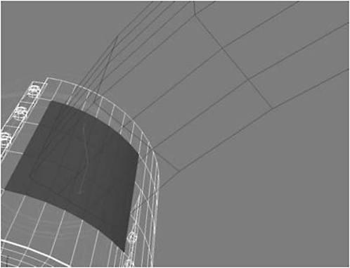
Figure 2-372

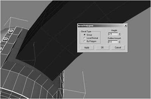
Figure 2-373
FYI: The contour of the wing makes it unevenly aligned with the contour of the brace. We need to fix that.

Figure 2-374
37. Switch to wireframe mode, switch to Vertex selection mode, and select the four vertices that comprise the wing tip, on the side that faces the nozzle.

Figure 2-375
38. Switch back to shaded/edged faces mode, switch the reference coordinate system to View, and scale the vertices down to 0 in the Y axis to straighten them.
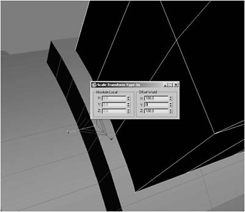
Figure 2-376
39. Now straighten the vertices on the intake side using the same technique.
40. Select the wing_brace, and select the 21 polygons beneath the wing tip that you selected before.
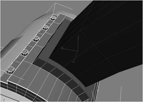
Figure 2-377
41. Click Bevel Settings:


Figure 2-378

Figure 2-379
43. Group Extrude the polygons –0.4.
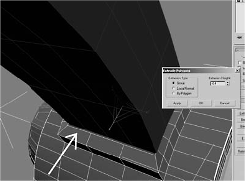
Figure 2-380
Fire Drill: If you have wide gaps between the wing tip and the wing_brace, it may be necessary to adjust the vertices of either the wing or the extrusion to make the wing fit into the wing_brace. We want a snug fit, but we also want enough of a gap so we can see it when we render. Look at the objects around you. Nearly all of them have some kind of seam.
44. Select the wing_brace and select the three polygons shown in Figure 2-381, on both the nozzle and the intake sides.
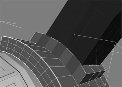
Figure 2-381

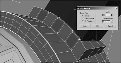
Figure 2-382

Figure 2-383
46. MSmooth the polygons.
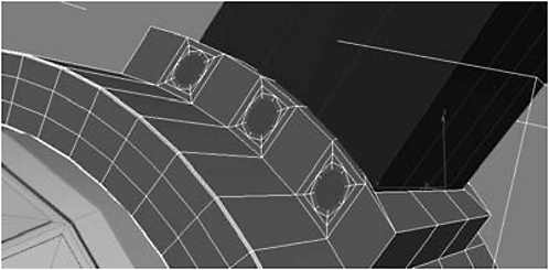
Figure 2-384
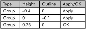

Figure 2-385
48. Select the middle polygon on the top and underneath sides of the wing_brace and repeat steps 45-47 to make upper and lower bolts.
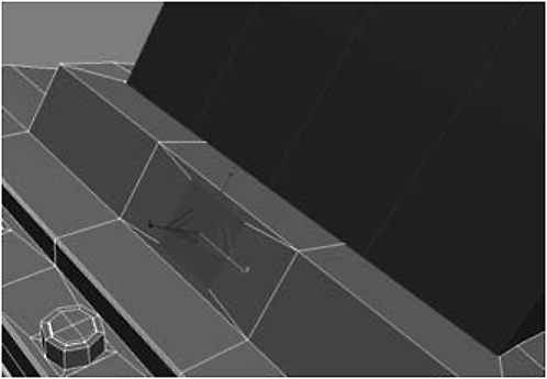
Figure 2-386
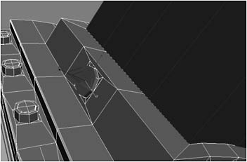
Figure 2-387
49. Select the 24 sharp outer edges making up the place the wing slips into, and Chamfer by 0.06 and then 0.02.

Figure 2-388
50. Select an inner edge, where the wing enters the wing_brace, click Loop, then Chamfer the edge by 0.06.
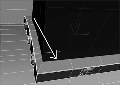
Figure 2-389
51. Unhide the rotors, zoom out so you can see the nacelle, brace, and wing, and do a test render.
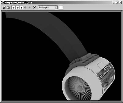
Figure 2-390
Day 8: Detailing the Wing
1. Select all the middle segments of the wing’s edge, both front and back (total of 24 edges).
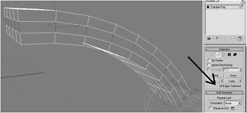
Figure 2-391
2. Click Connect to make a center seam.

Figure 2-392
3. Select the 16 polygons on the chassis side of the wing and delete them.

Figure 2-393
4. Target Weld the upper and lower vertices in the middle of the wing edge to the middle seam you made with the Connect tool; these target welds will result in a single seam running down the edges of the wings.
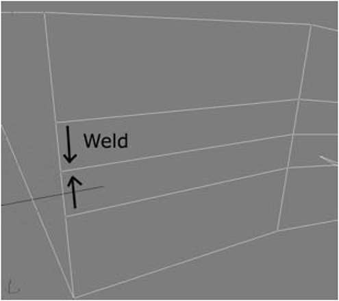
Figure 2-394
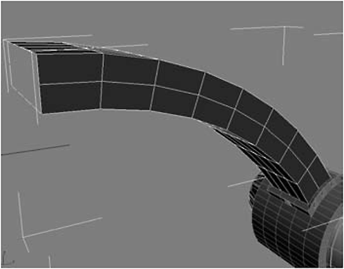
Figure 2-395
5. Select the eight top and top/side polygons that make up the rotor-side edge of the wing and click Bevel Settings:
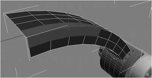
Figure 2-396
6. Bevel the six bottom polygons (Figure 2-397) using the same settings as you did in step 5.

Figure 2-397
7. Select the 14 polygons shown in Figure 2-398 (three polygons on top of the wing are not visible in the figure).
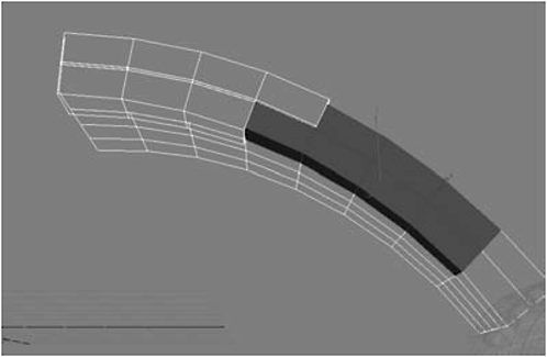
Figure 2-398
8. Bevel them using the same settings as in step 5.
9. Add the Clay material to the wing and do a test render to get a better sense of the detailing the last few steps have accomplished.

Figure 2-399
FYI: The bevel outlines make the gaps between the plates, while the bevel height forms the plates.
10. Select the polygons shown in Figure 2-400 and apply the same bevel settings we’ve been using.
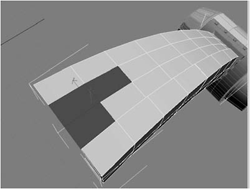
Figure 2-400
11. Select the polygons shown in Figure 2-401 and apply the same bevel settings we’ve been using.

Figure 2-401
12. Select the polygons shown in Figure 2-402 and apply the same bevel settings we’ve been using.
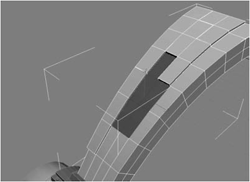
Figure 2-402
13. Select the polygons shown in Figure 2-403 and apply the same bevel settings we’ve been using.

Figure 2-403
14. Select the polygons shown in Figure 2-404 and apply the same bevel settings we’ve been using.
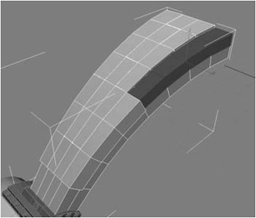
Figure 2-404
15. Select the polygons shown in Figure 2-405 and apply the same bevel settings we’ve been using.

Figure 2-405
16. Select the polygons shown in Figure 2-406 and apply the same bevel settings we’ve been using.

Figure 2-406
17. Select but do not bevel the polygons shown in Figure 2-407.
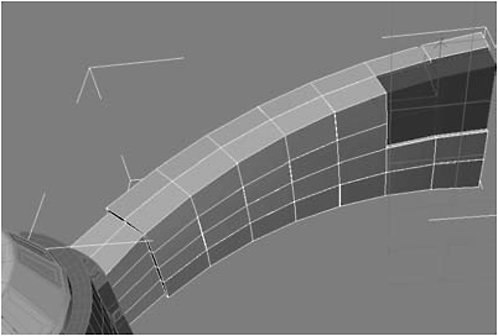
Figure 2-407

Figure 2-408
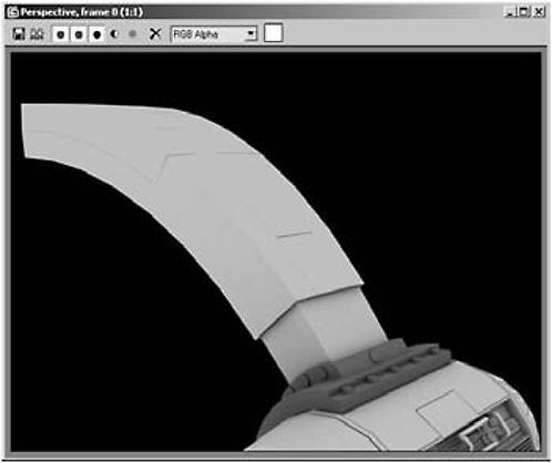
Figure 2-409
19. Select the same polygons you did in step 5 and Bevel them:
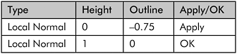

Figure 2-410

Figure 2-411
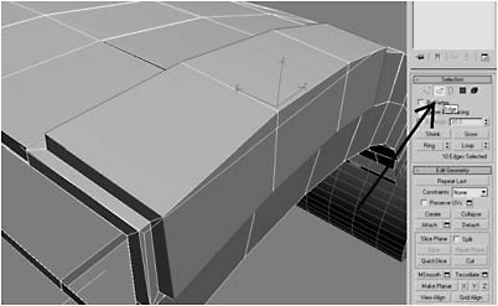
Figure 2-412
FYI: Shift + Edge selection mode switches from Polygon selection mode to Edge selection mode and highlights the outer edges of the selected polygons.
21. Chamfer the edges first by 0.06 and then by 0.2.
22. Repeat steps 20-21, using the same polygon selections you used in steps 5-16 to make the armored plates.
23. Do a test render.
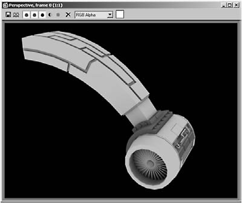
Figure 2-413
Message: You can put the rivets, which hold the armor to the wing, either on top of the plates or between them. It’s just a matter of personal taste. I’ve also intentionally left the armor off the area closest to the wing_brace. If you want to detach it, you can set up a rigging so that this part can slide into the wing, allowing you to animate the nacelle to move closer to the wing for certain maneuvers.
24. Switch to Edge selection mode and click the innermost edge of the chamfered edge of the rotor-side armored plate, closest to the chassis connection.
Fire Drill: It should loop for you but if it doesn’t, click Loop. As a last resort, because Loop is finicky, you may have to select them using Ctrl + left-click.

Figure 2-414
25. Under Edit Edges, click Create Shape From Selection (be sure to select Linear and not Smooth).
26. Hit H and select the shape you just made (Shape01).

Figure 2-415
27. Select the top and side segments and move them 0.4 in the X axis. (Hit F3 to switch between shaded and wireframe modes as needed.)

Figure 2-416
28. Select the bottom segments and move them up 0.4 in the Z axis.
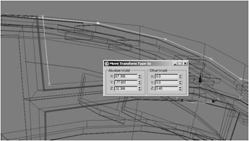
Figure 2-417
29. Select the four rear segments and move them –0.4 in the Y axis.
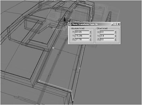
Figure 2-418
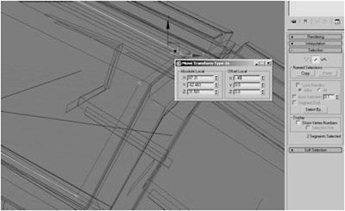
Figure 2-419
Fire Drill: If you slip back into shaded/edged faces mode, you’ll see that some of the vertices have fallen below the surface of the armor plates.

Figure 2-420
31. Use the Move tool to ensure all the vertices are just above the surface.
32. Switch to the Front viewport. Using AutoGrid, create a Sphere with a Radius of 0.25, 18 Segments, and a Hemisphere of 0.5 at the bottom corner of the armor plate, at the location of the spline vertex.
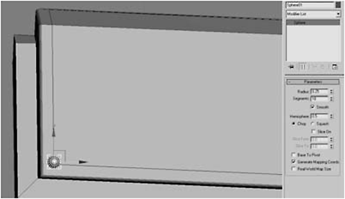
Figure 2-421
33. Convert the sphere to an Editable Polygon and delete the rear-facing polygons.
34. Object-select the sphere and select the Spacing tool (Shift+I)from the Tools menu.

Figure 2-422
35. Click Pick Path and click the spline shape object you made. Type 30 into the Count field, make sure Context is set to Centers and Type of Object is set to Copy, then click Apply and close the window.
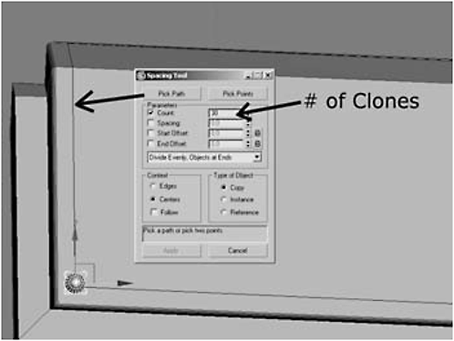
Figure 2-423

Figure 2-424
FYI: The spline was a guide for Max to use when positioning the clones. We no longer need it.
Cloning to a path is a huge time-saver when cloning in two dimensions. However, the Spacing tool is not without problems. Specifically, when the clones follow a path over multiple axes, the clones get turned the wrong way, necessitating the use of the Rotation tool. Even so, it’s quicker and more accurate than placing them by hand. Also, make sure the bottom edge of each sphere is just below the surface, so when you attach them, there won’t be gaps beneath the rivets and the surface.
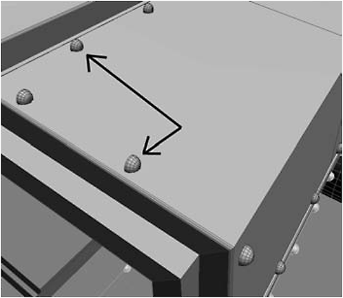
Figure 2-425
37. Select the wing, click Attach List, and attach all the spheres.
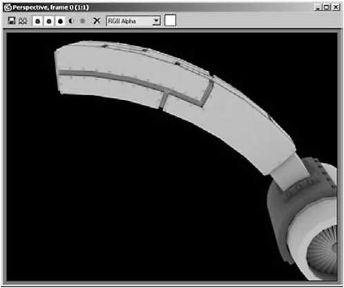
Figure 2-426
Message: Let’s be real. Making all those rivets is a pain in the butt, because it’s about as interesting as watching paint dry. That said, if you look at Figure 2-426, the rivets are really indispensible, because they ’re what sell it as being armor plating.
39. Rotate around the back and delete the extra polygons that were made from the bevels and that face where the wing connects to the chassis.
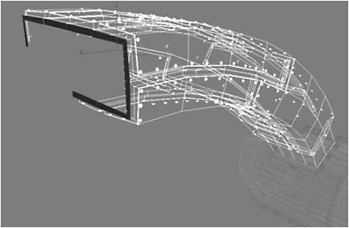
Figure 2-427