
Multi-Antenna Transmission
Abstract
This chapter gives a background to multi-antenna transmission in general, followed by a detailed description on NR multi-antenna precoding for both the downlink and uplink transmission directions.
Keywords
Multi-antenna transmission; multi-antenna precoding; codebook-based transmission; non-codebook-based transmission
Multi-antenna transmission is a key component of NR, especially at higher frequencies. This chapter gives a background to multi-antenna transmission in general, followed by a detailed description on NR multi-antenna precoding.
11.1 Introduction
The use of multiple antennas for transmission and/or reception can provide substantial benefits in a mobile-communication system.
Multiple antennas at the transmitter and/or receiver side can be used to provide diversity against fading by utilizing the fact that the channels experienced by different antennas may be at least partly uncorrelated, either due to sufficient inter-antenna distance or due to different polarization between the antennas.
Furthermore, by carefully adjusting the phase, and possibly also the amplitude, of each antenna element, multiple antennas at the transmitter side can be used to provide directivity, that is, to focus the overall transmitted power in a certain direction (beam forming) or, in the more general case, to specific locations in space. Such directivity can increase the achievable data rates and range due to higher power reaching the target receiver. Directivity will also reduce the interference to other links, thereby improving the overall spectrum efficiency.
Similarly, multiple receive antennas can be used to provide receiver-side directivity, focusing the reception in the direction of a target signal, while suppressing interference arriving from other directions.
Finally, the presence of multiple antennas at both the transmitter and the receiver sides can be used to enable spatial multiplexing, that is, transmission of multiple “layers” in parallel using the same time/frequency resources.
In LTE, multi-antenna transmission/reception for diversity, directivity, and spatial multiplexing is a key tool to enable high data rates and high system efficiency. However, multi-antenna transmission/reception is an even more critical component for NR due to the possibility for deployment at much higher frequencies compared to LTE.
There is a well-established and to a large extent correct assumption that radio communication at higher frequencies is associated with higher propagation loss and correspondingly reduced communication range. However, at least part of this is due to an assumption that the dimensions of the receiver antenna scale with the wavelength, that is, with the inverse of the carrier frequency. As an example, a tenfold increase in the carrier frequency, corresponding to a tenfold reduction in the wave length, is assumed to imply a corresponding tenfold reduction in the physical dimensions of the receiver antenna or a factor of 100 reduction in the physical antenna area. This corresponds to a 20 dB reduction in the energy captured by the antenna.
If the receiver antenna size would instead be kept unchanged as the carrier frequency increases, the reduction in captured energy could be avoided. However, this would imply that the antenna size would increase relative to the wave length, something that inherently increases the directivity of the antenna.1 The gain with the larger antenna size can thus only be realized if the receive antenna is well directed towards the target signal.
By also keeping the size of the transmitter-side antenna unchanged, in practice increasing the transmit-antenna directivity, the link budget at higher frequencies can be further improved. Assuming line-of-sight propagation and ignoring other losses, the overall link budget would then actually improve for higher frequencies. In practice there are many other factors that negatively impact the overall propagation losses at higher frequencies such as higher atmospheric attenuation and less diffraction leading to degraded non-line-of-sight propagation. Still, the gain from higher antenna directivity at higher frequencies is widely utilized in point-to-point radio links where the use of highly directional antennas at both the transmitter and receiver sides, in combination with line-of-sight links, allows for relatively long-range communication despite operation at very high frequencies.
In a mobile-communication system with devices located in many different directions relative to the base station and the devices themselves having an essentially random rotational direction, the use of fixed highly directional antennas is obviously not applicable. However, a similar effect, that is, an extension of the overall receive antenna area enabling higher-directivity transmission, can also be achieved by means of an antenna panel consisting of many small antenna elements. In this case, the dimension of each antenna element, as well as the distance between antenna elements, is proportional to the wave length. As the frequency increases, the size of each antenna element, as well as their mutual distances, is thus reduced. However, assuming a constant size of the overall antenna configuration, this can be compensated for by increasing the number of antenna elements. Fig. 11.1 shows an example of such an antenna panel consisting of 64 dual-polarized antenna elements and targeting the 28 GHz band. The AAA battery is included in the picture as an indication of the overall size of the antenna panel.

The benefit of such an antenna panel with a large number of small antenna elements, compared to a single large antenna, is that the direction of the transmitter beam can be adjusted by separately adjusting the phase of the signals applied to each antenna element. The same effect can be achieved when a multi-antenna panel, such as the one illustrated in Fig. 11.1, is used on the receiver side, that is, the receiver beam direction can be adjusted by separately adjusting the phases of the signals received at each antenna element.
In general, any linear multi-antenna transmission scheme can be modeled according to Fig. 11.2 with ![]() layers, captured by the vector
layers, captured by the vector ![]() , being mapped to
, being mapped to ![]() transmit antennas (the vector
transmit antennas (the vector ![]() ) by means of multiplication with a matrix
) by means of multiplication with a matrix ![]() of size
of size ![]() .
.

The general model of Fig. 11.2 applies to most cases of multi-antenna transmission. However, depending on implementation there will be various degrees of constraints that will impact the actual capabilities of the multi-antenna transmission.
One such implementation aspect relates to where, within the overall physical transmitter chain, the multi-antenna processing, that is, the matrix ![]() of Fig. 11.3, is applied. On a high level one can distinguish between two cases:
of Fig. 11.3, is applied. On a high level one can distinguish between two cases:
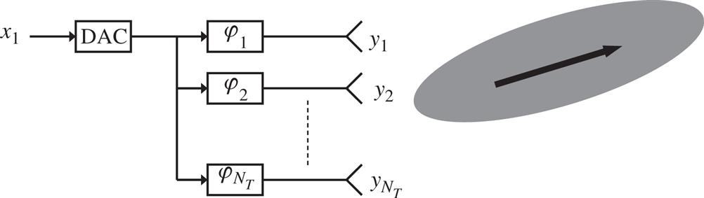
- • The multi-antenna processing is applied within the analog part of the transmitter chain, that is, after digital-to-analog conversion (left part of Fig. 11.3);
- • The multi-antenna processing is applied within the digital part of the transmitter chain, that is, before digital-to-analog conversion (right part of Fig. 11.3).

The main drawback of digital processing according to the right part of Fig. 11.3 is the implementation complexity, especially the need for one digital-to-analog converter per antenna element. In the case of operation at higher frequencies with a large number of closely spaced antenna elements, analog multi-antenna processing according to the left part of Fig. 11.3 will therefore be the most common case, at least in the short- and medium-term perspectives. In this case, the multi-antenna transmission will typically be limited to per-antenna phase shifts providing beam forming (see Fig. 11.4).
It should be noted that this may not be a severe limitation as operation at higher frequencies is typically more often power-limited than bandwidth-limited, making beam forming more important than, for example, high-order spatial multiplexing. The opposite is often true for lower frequency bands where the spectrum is a more sparse resource with less possibility for wide transmission bandwidths.
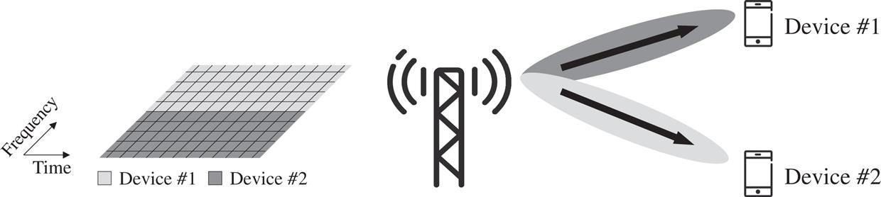
Analog processing typically also implies that any beam forming is carried out on a per-carrier basis. For the downlink transmission direction, this implies that it is not possible to frequency multiplex beam-formed transmissions to devices located in different directions relative to the base station. In other words, beam-formed transmissions to different devices located in different directions must be separated in time as illustrated in Fig. 11.5.
In other cases, especially in the case of a smaller number of antenna elements at lower frequencies, multi-antenna processing can be applied in the digital domain according to the right part of Fig. 11.3. This enables much higher flexibility in the multi-antenna processing with a possibility for high-order spatial multiplexing and with the transmission matrix ![]() being a general
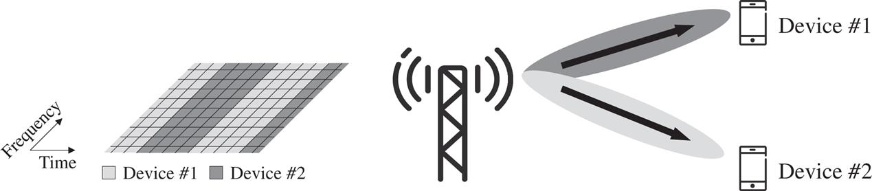
being a general ![]() matrix where each element may include both a phase shift and a scale factor. Digital processing also allows for independent multi-antenna processing for different signals within the same carrier, enabling simultaneous beam-formed transmission to multiple devices located in different directions relative to the base station also by means of frequency multiplexing as illustrated Fig. 11.6.
matrix where each element may include both a phase shift and a scale factor. Digital processing also allows for independent multi-antenna processing for different signals within the same carrier, enabling simultaneous beam-formed transmission to multiple devices located in different directions relative to the base station also by means of frequency multiplexing as illustrated Fig. 11.6.
In the case of digital processing, or more generally in the case where the antenna weights can be flexibly controlled, the transmission matrix ![]() is often refererred to as a precoder matrix and the multi-antenna processing is often referred to as multi-antenna precoding.
is often refererred to as a precoder matrix and the multi-antenna processing is often referred to as multi-antenna precoding.
The difference in capabilities between analog and digital multi-antenna processing also applies to the receiver side. In the case of analog processing, the multi-antenna processing is applied in the analog domain before analog-to-digital conversion. In practice, the multi-antenna processing is then limited to receiver-side beam forming where the receiver beam can only be directed in one direction at a time. Reception from two different directions must then take place at different time instances.
Digital implementation, on the other hand, provides full flexibility, supporting reception of multiple layers in parallel and enabling simultaneous beam-formed reception of multiple signals arriving from different directions.
Similar to the transmitter side, the drawback of digital multi-antenna processing on the receiver side is in terms of complexity, especially the need for one analog-to-digital converter per antenna element.
For the remainder of this chapter we will focus on multi-antenna precoding, that is, multi-antenna transmission with full control over the precoder matrix. The limitations of analog processing and how those imitations are impacting the NR design are discussed in Chapter 12.
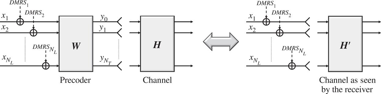
One important aspect of multi-antenna precoding is whether or not the precoding is also applied to the demodulation reference signals (DMRSs) used to support coherent demodulation of the precoded signal.
If the DMRSs are not precoded, the receiver needs to be informed about what precoder is used at the transmitter side to enable proper coherent demodulation of the precoded data transmission.
On the other hand, if the reference signals are precoded together with the data, the precoding can, from a receiver point of view, be seen as part of the overall multidimensional channel (see Fig. 11.7). Simply speaking, instead of the “true” ![]() channel matrix
channel matrix ![]() , the receiver will see a channel
, the receiver will see a channel ![]() of size
of size ![]() that is the concatenation of the channel
that is the concatenation of the channel ![]() with whatever precoding
with whatever precoding ![]() is applied at the transmitter side. The precoding is thus transparent to the receiver implying that the transmitter can, at least in principle, select an arbitrary precoder matrix and does not need to inform the receiver about the selected precoder.
is applied at the transmitter side. The precoding is thus transparent to the receiver implying that the transmitter can, at least in principle, select an arbitrary precoder matrix and does not need to inform the receiver about the selected precoder.
11.2 Downlink Multi-Antenna Precoding
All NR downlink physical channels rely on channel-specific DMRSs to support coherent demodulation. Furthermore, a device can assume that the DMRSs are jointly precoded with the data in line with Fig. 11.7. Consequently, any downlink multi-antenna precoding is transparent to the device and the network can, in principle, apply any transmitter-side precoding with no need to inform the device what precoding is applied.2
The specification impact of downlink multi-antenna precoding is therefore mainly related to the measurements and reporting done by the device to support network selection of precoder for downlink PDSCH transmission. These precoder-related measurements and reporting are part of the more general CSI reporting framework based on report configurations as described in Section 8.2. As described there, a CSI report may consist of one or several of the following quantities:
- • A Rank Indicator (RI), indicating what the device believes is a suitable transmission rank, that is, a suitable number of transmission layers
 for the downlink transmission;
 - • A Precoder-Matrix Indicator (PMI), indicating what the device believes is a suitable precoder matrix, given the selected rank;
- • A Channel-Quality Indicator (CQI), in practice indicating what the device believes is a suitable channel-coding rate and modulation scheme, given the selected precoder matrix.
As mentioned above, the PMI reported by a device indicates what the device believes is a suitable precoder matrix to use for downlink transmission to the device. Each possible value of the PMI thus corresponds to one specific precoder matrix. The set of possible PMI values thus corresponds to a set of different precoder matrices, referred to as the precoder codebook, that the device can select between when reporting PMI. Note that the device selects PMI based on a certain number of antenna ports ![]() , given by the number of antenna ports of the configured CSI-RS associated with the report configuration, and the selected rank
, given by the number of antenna ports of the configured CSI-RS associated with the report configuration, and the selected rank ![]() . There is thus at least one codebook for each valid combination of
. There is thus at least one codebook for each valid combination of ![]() and
and ![]() .
.
It is important to understand that the precoder codebooks for downlink multiantenna precoding are only used in the context of PMI reporting and do not impose any restrictions on what precoder matrix is eventually used by the network for downlink transmission to the reporting device. The network can use whatever precoder it wants and the precoder selected by the network does not have to be part of any defined codebook.
In many cases it obviously makes sense for the network to use the precoder indicated by the reported PMI. However, in other cases the network may have additional input that speaks in favor of a different precoder. As an example, multi-antenna precoding can be used to enable simultaneous downlink transmission to multiple devices using the same time/frequency resources, so-called multi-user MIMO (MU-MIMO). The basic principle of MU-MIMO based on multi-antenna precoding is to choose precoding matrices that not only focus the energy towards the target device but also limit interference to other simultaneously scheduled devices. In this case, the selection of precoding for transmission to a specific device should not only take into account the PMI reported by that device (which only reflects the channel experienced by that device). Rather, the selection of precoding for transmission to a specific device should, in the general case, take into account the PMI reported by all simultaneously scheduled devices.
To conclude on suitable precoding in the MU-MIMO scenario typically also requires more detailed knowledge of the channel experienced by each device, compared to precoding in the case of transmission to a single device. For this reason, NR defines two types of CSI that differ in the structure and size of the precoder codebooks, Type I CSI and Type II CSI.
- • Type I CSI primarily targets scenarios where a single user is scheduled within a given time/frequency resource (no MU-MIMO), potentially with transmission of a relatively large number of layers in parallel (high-order spatial multiplexing);
- • Type II CSI primarily targets MU-MIMO scenarios with multiple devices being scheduled simultaneously within the same time/frequency resource but with only a limited number of spatial layers (maximum of two layers) per scheduled device.
The codebooks for Type I CSI are relatively simple and primarily aim at focusing the transmitted energy at the target receiver. Interference between the potentially large number of parallel layers is assumed to be handled primarily by means of receiver processing utilizing multiple receive antennas.
The codebooks for Type II CSI are significantly more extensive, allowing for the PMI to provide channel information with much higher spatial granularity. The more extensive channel information allows the network to select a downlink precoder that not only focuses the transmitted energy at the target device but also limits the interference to other devices scheduled in parallel on the same time/frequency resource. The higher spatial granularity of the PMI feedback comes at the cost of significantly higher signaling overhead. While a PMI report for Type I CSI will consist of at most a few tens of bits, a PMI report for Type II CSI may consist of several hundred bits. Type II CSI is therefore primarily applicable for low-mobility scenarios where the feedback periodicity in time can be reduced.
Below we will give an overview of the different types of CSI. For a more detailed description, for example, see [64].
11.2.1 Type I CSI
There are two subtypes of Type I CSI, referred to as Type I single-panel CSI and Type I multi-panel CSI, corresponding to different codebooks. As the names suggest, the codebooks have been designed assuming different antenna configurations on the network/transmitter side.
Note that an assumption of a specific antenna configuration when designing a codebook does not mean that the codebook cannot be used in deployments based on a different antenna configuration. When a device, based on downlink measurements, selects a precoder matrix from a codebook, it does not make any assumptions regarding the antenna configuration at the network side but simply selects what it believes is the most suitable precoder in the codebook, given the estimated channel conditions.
11.2.1.1 Single-Panel CSI
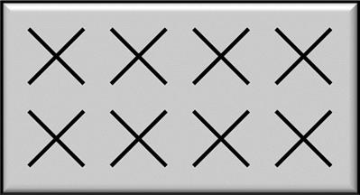
As the name suggests, the codebooks for Type I single-panel CSI are designed assuming a single antenna panel with ![]() cross-polarized antenna elements. An example is illustrated in Fig. 11.8 for the case of (
cross-polarized antenna elements. An example is illustrated in Fig. 11.8 for the case of (![]() ,
, ![]() ) = (4, 2), that is, a 16-port antenna.3
) = (4, 2), that is, a 16-port antenna.3

In general, the precoder matrices ![]() in the codebooks for Type I single-panel CSI can be expressed as the product of two matrices
in the codebooks for Type I single-panel CSI can be expressed as the product of two matrices ![]() and
and ![]() with information about the selected
with information about the selected ![]() and
and ![]() reported separately as different parts of the overall PMI.
reported separately as different parts of the overall PMI.
The matrix ![]() is assumed to capture long-term frequency-independent characteristics of the channel. A single
is assumed to capture long-term frequency-independent characteristics of the channel. A single ![]() is therefore selected and reported for the entire reporting bandwidth (wideband feedback).
is therefore selected and reported for the entire reporting bandwidth (wideband feedback).
In contrast, the matrix ![]() is assumed to capture more short-term and potentially frequency-dependent characteristics of the channel. The matrix can therefore be selected and reported on a subband basis where a subband covers a fraction of the overall reporting bandwidth. Alternatively, the device may not report
is assumed to capture more short-term and potentially frequency-dependent characteristics of the channel. The matrix can therefore be selected and reported on a subband basis where a subband covers a fraction of the overall reporting bandwidth. Alternatively, the device may not report ![]() at all, in which case the device, when subsequently selecting CQI, should assume that the network randomly selects
at all, in which case the device, when subsequently selecting CQI, should assume that the network randomly selects ![]() on a per PRG (Physical Resource Block Group, see Section 9.8) basis. Note that this does not impose any restrictions on the actual precoding applied at the network side but is only about assumptions made by the device when selecting CQI.
on a per PRG (Physical Resource Block Group, see Section 9.8) basis. Note that this does not impose any restrictions on the actual precoding applied at the network side but is only about assumptions made by the device when selecting CQI.
On a high level, the matrix ![]() can be seen as defining a beam or, in some cases a set of neighbor beams, pointing in a specific direction. More specifically, the matrix
can be seen as defining a beam or, in some cases a set of neighbor beams, pointing in a specific direction. More specifically, the matrix ![]() can be written as
can be written as
where each column of the matrix B defines a beam and the ![]() block structure is due to the two polarizations. Note that, as the matrix
block structure is due to the two polarizations. Note that, as the matrix ![]() is assumed to only capture long-term frequency-independent channel characteristics, the same beam direction can be assumed to fit both polarization directions.
is assumed to only capture long-term frequency-independent channel characteristics, the same beam direction can be assumed to fit both polarization directions.
Selecting the matrix ![]() or, equivalently,
or, equivalently, ![]() can thus be seen as selecting a specific beam direction from a large set of possible beam directions defined by the full set of
can thus be seen as selecting a specific beam direction from a large set of possible beam directions defined by the full set of ![]() matrices within the codebook.4
matrices within the codebook.4
In the case of rank 1 or rank 2 transmission, either a single beam or four neighbor beams are defined by the matrix ![]() . In the case of four neighboring beams, corresponding to four columns in
. In the case of four neighboring beams, corresponding to four columns in ![]() , the matrix
, the matrix ![]() then selects the exact beam to be used for the transmission. As
then selects the exact beam to be used for the transmission. As ![]() can be reported on a subband basis, it is thus possible to fine-tune the beam direction per subband. In addition,
can be reported on a subband basis, it is thus possible to fine-tune the beam direction per subband. In addition, ![]() provides co-phasing between the two polarizations. In the case when
provides co-phasing between the two polarizations. In the case when ![]() only defines a single beam, corresponding to
only defines a single beam, corresponding to ![]() being a single-coumn matrix, the matrix
being a single-coumn matrix, the matrix ![]() only provides co-phasing between the two polarizations.
only provides co-phasing between the two polarizations.
For transmission ranks ![]() larger than 2, the matrix
larger than 2, the matrix ![]() defines
defines ![]() orthogonal beams where
orthogonal beams where ![]() . The
. The ![]() beams, together with the two polarization directions in each beam are then used for transmission of the R layers, with the matrix
beams, together with the two polarization directions in each beam are then used for transmission of the R layers, with the matrix ![]() only providing cophasing between the two polarizations. Up to eight layers can be transmitted to the same device.
only providing cophasing between the two polarizations. Up to eight layers can be transmitted to the same device.
11.2.1.2 Multipanel CSI
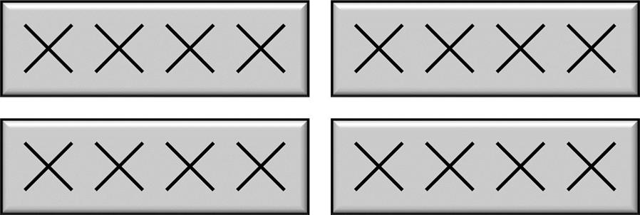
In contrast to single-panel CSI, codebooks for Type I multi-panel CSI are designed assuming the joint use of multiple antenna panels at the network side and takes into account that it may be difficult to ensure coherence between transmissions from different panels. More specifically, the design of the multi-panel codebooks assumes an antenna configuration with two or four two-dimensional panels, each with ![]() cross-polarized antenna elements. An example of such a multi-panel antenna configuration is illustrated in Fig. 11.9 for the case of four antenna panels and
cross-polarized antenna elements. An example of such a multi-panel antenna configuration is illustrated in Fig. 11.9 for the case of four antenna panels and ![]() , that is, a 32-port antenna.
, that is, a 32-port antenna.
 .
.The basic principle of Type 1 multi-panel CSI is the same as that of Type 1 single-panel CSI, except that the matrix ![]() defines one beam per polarization and panel. The matrix
defines one beam per polarization and panel. The matrix ![]() then provides per-subband co-phasing between polarizations as well as panels.
then provides per-subband co-phasing between polarizations as well as panels.
The Type I multi-panel CSI supports spatial multiplexing with up to four layers.
11.2.2 Type II CSI
As already mentioned, Type II CSI provides channel information with significantly higher spatial granularity compared to Type I CSI. Similar to Type I CSI, Type II CSI is based on wideband selection and reporting of beams from a large set of beams. However, while Type I CSI in the end selects and reports a single beam, Type II CSI may select and report up to four orthogonal beams. For each selected beam and each of the two polarizations, the reported PMI then provides an amplitude value (partly wideband and partly subband) and a phase value (subband). In the end, this provides a much more detailed model of the channel, capturing the main rays and their respective amplitude and phase.
At the network side, the PMI delivered from multiple devices can then be used to identify a set of devices to which transmission can be done simultaneously on a set of time/frequency resources (MU-MIMO) and what precoder to use for each transmission.
As the Type II CSI is targeting the MU-MIMO scenario, transmission is limited to up to two layers per device.
11.3 NR Uplink Multiantenna Precoding
NR support uplink (PUSCH) multi-antenna precoding with up to four layers. However, as mentioned earlier, in the case of DFT-based transform precoding (see Chapter 9), only single-layer transmission is supported.
The device can be configured in two different modes for PUSCH multi-antenna precoding, referred to as codebook-based transmission and non-codebook-based transmission, respectively. The selection between these two transmission modes is at least partly dependent on what can be assumed in terms of uplink/downlink channel reciprocity, that is, to what extent it can be assumed that the detailed uplink channel conditions can be estimated by the device based on downlink measurements.
Like the downlink, any uplink (PUSCH) multi-antenna precoding is also assumed to be applied to the DMRS used for the PUSCH coherent demodulation. Similar to the downlink transmission direction, uplink precoding is thus transparent to the receiver in the sense that receiver-side demodulation can be carried out without knowledge of the exact precoding applied at the transmitter (device) side. Note though that this does not necessarily imply that the device can freely choose the PUSCH precoder. In the case of codebook-based precoding, the scheduling grant includes information about a precoder, similar to the device providing the network with PMI for downlink multiantenna precoding. However, in contrast to the downlink, where the network may or may not use the precoder matrix indicated by the PMI, in the uplink direction the device is assumed to use the precoder provided by the network. As we will see in Section 11.3.2, also in the case of non-codebook-based transmission will the network have an influence on the final choice of uplink precoder.
Another aspect that may put constraints on uplink multi-antenna transmission is to what extent one can assume coherence between different device antennas, that is, to what extent the relative phase between the signals transmitted on two antennas can be well controlled. Coherence is needed in the case of general multi-antenna precoding where antenna-port-specific weight factors, including specific phase shifts, are applied to the signals transmitted on the different antenna ports. Without coherence between the antenna ports the use of such antenna-port-specific weight factors is obviously meaningless as each antenna port would anyway introduce a more or less random relative phase.
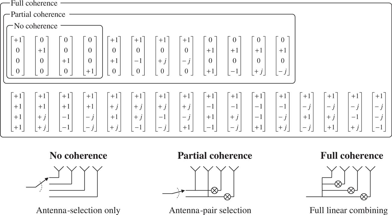
The NR specification allows for different device capabilities with regards to such inter-antenna-port coherence, referred to as full coherence, partial coherence, and no coherence, respectively.
In the case of full coherence, it can be assumed that the device can control the relative phase between any of the up to four ports that are to be used for transmission.
In the case of partial coherence, the device is capable of pairwise coherence, that is, the device can control the relative phase within pairs of ports. However, there is no guarantee of coherence, that is, a controllable phase, between the pairs.
Finally, in the case of no coherence there is no guarantee of coherence between any pair of the device antenna ports.
11.3.1 Codebook-Based Transmission
The basic principle of codebook-based transmission is that the network decides on an uplink transmission rank, that is, the number of layers to be transmitted, and a corresponding precoder matrix to use for the transmission. The network informs the device about the selected transmission rank and precoder matrix as part of the uplink scheduling grant. At the device side, the precoder matrix is then applied for the scheduled PUSCH transmission, mapping the indicated number of layers to the antenna ports.
To select a suitable rank and a corresponding precoder matrix, the network needs estimates of the channels between the device antenna ports and the corresponding network receive antennas. To enable this, a device configured for codebook-based PUSCH would typically be configured for transmission of at least one multi-port SRS. Based on measurements on the configured SRS, the network can sound the channel and determine a suitable rank and precoder matrix.
The network cannot select an arbitrary precoder. Rather, for a given combination of number of antenna ports ![]() (
(![]() or
or ![]() ) and transmission rank
) and transmission rank ![]() (
(![]() ), the network selects the precoder matrix from a limited set of available precoders (the “uplink codebook”).
), the network selects the precoder matrix from a limited set of available precoders (the “uplink codebook”).
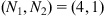
As an example, Fig. 11.10 illustrates the available precoder matrices, that is, the code books for the case of two antenna ports.
When selecting the precoder matrix, the network needs to consider the device capability in terms of antenna-port coherence (see above). For devices not supporting coherence, only the first two precoder matrixes can therefore be used in the case of single-rank transmission.
It can be noted that restricting the codebook selection to these two matrices is equivalent to selecting either the first or second antenna port for transmission. In the case of such antenna selection, a well-controlled phase, that is, coherence between the antenna ports, is not required. On the other hand, the remaining precoder vectors imply linear combination of the signals on the different antenna ports, which requires coherence between the antenna ports.
In the case of rank-2 transmission (![]() ) only the first matrix, which does not imply any coupling between the antenna ports, can be selected for devices that do not support coherence.
) only the first matrix, which does not imply any coupling between the antenna ports, can be selected for devices that do not support coherence.
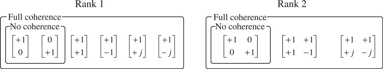
To further illustrate the impact of no, partial, and full coherence, Fig. 11.11 illustrates the full set of rank-1 precoder matrices for the case of four antenna ports. Once again, the matrices corresponding to no coherence are limited to antenna-port selection. The extended set of matrices corresponding to partial coherence allows for linear combination within pairs of antenna ports with selection between the pairs. Finally, full coherence allows for a linear combination over all four antenna ports.
The above-described NR codebook-based transmission for PUSCH is essentially the same as the corresponding codebook-based transmission for LTE except that NR supports somewhat more extensive codebooks. Another more fundamental extension of NR codebook-based PUSCH transmission, compared to LTE, is that a device can be configured to transmit multiple multi-port SRS.5 In the case of such multi-SRS transmission, the network feedback is extended with a one-bit SRS resource indicator (SRI) indicating one of the configured SRSs. The device should then use the precoder provided in the scheduling grant and map the output of the precoding to the antenna ports corresponding to the SRS indicated in the SRI. In terms of the spatial filter F discussed in Chapter 8, the different SRSs would typically be transmitted using different spatial filters. The device should then transmit the precoder signal using the same spatial filter as used for the SRS indicated by the SRI.
One way to visualize the use of multiple SRS for codebook-based PUSCH transmission is to assume that the device transmits the multi-port SRS within separate, relatively large beams (see Fig. 11.12). These beams may, for example, correspond to different device antenna panels with different directions, where each panel includes a set of antenna elements, corresponding to the antenna ports of each multi-port SRS. The SRI received from the network then determines what beam to use for the transmission while the precoder information (number of layers and precoder) determines how the transmission is to be done within the selected beam. As an example, in the case of full-rank transmission the device will do full-rank transmission within the beam corresponding to the SRS selected by the network and signaled by means of SRI (upper part of Fig. 11.12). At the other extreme, in the case of single-rank transmission the precoding will in practice create additional beam forming within the wider beam indicated by the SRI (lower part of Fig. 11.12).

Codebook-based precoding is typically used when uplink/downlink reciprocity does not hold, that is, when uplink measurements are needed in order to determine a suitable uplink precoding.
11.3.2 Non-codebook-Based Precoding
In contrast to codebook-based precoding, which is based on network measurements and selection of uplink precoder, non-codebook-based precoding is based on device measurements and precoder indications to the network. The basic principle of uplink non-codebook-based precoding is illustrated in Fig. 11.13, with further explanation below.

Based on downlink measurements, in practice measurements on a configured CSI-RS, the device selects what it believes is a suitable uplink multi-layer precoder. Non-codebook-based precoding is thus based on an assumption of channel reciprocity, that is, that the device can acquire detailed knowledge of the uplink channel based on downlink measurements. Note that there are no restrictions on the device selection of precoder, thus the term “non-codebook-based.”
Each column of a precoder matrix ![]() can be seen as defining a digital “beam” for the corresponding layer. The device selection of precoder for
can be seen as defining a digital “beam” for the corresponding layer. The device selection of precoder for ![]() layers can thus be seen as the selection of
layers can thus be seen as the selection of ![]() different beam directions where each beam corresponds to one possible layer.
different beam directions where each beam corresponds to one possible layer.
In principle, PUSCH transmission could be done directly as transmission of ![]() layers based on the device-selected precoding. However, device selection of a precoder based on downlink measurements may not necessarily be the best precoder from a network point of view. Thus, the NR non-codebook-based precoding includes an additional step where the network can modify the device-selected precoder, in practice remove some “beams,” or equivalently some columns, from the selected precoder.
layers based on the device-selected precoding. However, device selection of a precoder based on downlink measurements may not necessarily be the best precoder from a network point of view. Thus, the NR non-codebook-based precoding includes an additional step where the network can modify the device-selected precoder, in practice remove some “beams,” or equivalently some columns, from the selected precoder.
To enable this, the device applies the selected precoder to a set of configured SRSs, with one SRS transmitted on each layer or “beam” defined by the precoder (step 2 in Fig. 11.13). Based on measurements on the received SRS, the network can then decide to modify the device-selected precoder for each scheduled PUSCH transmission. This is done by indicating a subset of the configured SRSs within the SRS resource indicator (SRI) included in the scheduling grant (step 3).6 The device then carries out the scheduled PUSCH transmission (step 4) using a reduced precoder matrix where only the columns corresponding to the SRSs indicated within the SRI are included. Note that the SRI then also implicitly defines the number of layers to be transmitted.
It should be noted that the device indication of precoder selection (step 2 in Fig. 11.13) is not done for each scheduled transmission. The uplink SRS transmission indicating device precoder selection can take place periodically (periodic or semipersistent SRS) or on demand (aperiodic SRS). In contrast, the network indication of precoder, that is in practice the network indication of the subset of beams of the device precoder, is then done for each scheduled PUSCH transmission.