
Beam Management
Abstract
This chapter describes the NR mechanisms for beam management. This includes mechanisms for initial beam adjustment, beam adjustment, and recovery from beam failures.
Keywords
Beam management; beam pair; beam adjustment; beam recovery; beam failure
Chapter 11 discussed multi-antenna transmission in general and then focused on multi-antenna precoding. A general assumption for the discussion on multi-antenna precoding was the possibility for detailed control, including both phase adjustment and amplitude scaling, of the different antenna elements. In practice this requires that multi-antenna processing at the transmitter side is carried out in the digital domain before digital-to-analog conversion. Likewise, the receiver multi-antenna processing must be carried out after analog-to-digital conversion.
However, in the case of operation at higher frequencies with a large number of closely space antenna elements, the antenna processing will rather be carried out in the analog domain with focus on beam-forming. As analog antenna processing will be carried out on a carrier basis, this also implies that beam-formed transmission can only be done in one direction at a time. Downlink transmissions to different devices located in different directions relative to the base station must therefore be separated in time. Likewise, in the case of analog-based receiver-side beam-forming, the receive beam can only focus in one direction at a time.
The ultimate task of beam management is, under these conditions, to establish and retain a suitable beam pair, that is, a transmitter-side beam direction and a corresponding receiver-side beam direction that jointly provide good connectivity.
As illustrated in Fig. 12.1, the best beam pair may not necessarily correspond to transmitter and receiver beams that are physically pointing directly towards each other. Due to obstacles in the surrounding environment, such a “direct” path between the transmitter and receiver may be blocked and a reflected path may provide better connectivity, as illustrated in the right-hand part of Fig. 12.1. This is especially true for operation in higher-frequency bands with less “around-the-corner” dispersion. The beam-management functionality must be able to handle such a situation and establish and retain a suitable beam pair also in this case.
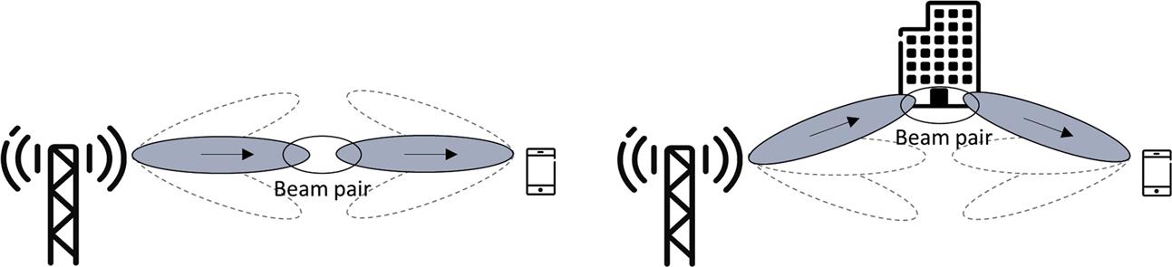
Fig. 12.1 illustrates the case of beam forming in the downlink direction, with beam-based transmission at the network side and beam-based reception at the device side. However, beam forming is at least as relevant for the uplink transmission direction with beam-based transmission at the device side and corresponding beam-based reception at the network side.
In many cases, a suitable transmitter/receiver beam pair for the downlink transmission direction will also be a suitable beam pair for the uplink transmission direction and vice versa. In 3GPP this is referred to as (downlink/uplink) beam correspondence. In the case of beam correspondence, it is sufficient to explicitly determine a suitable beam pair in one of the transmission directions. The same pair can then be used also in the opposite transmission direction.
As beam management is not intended to track fast and frequency-selective channel variations, beam correspondence does not require that downlink and uplink transmission take place on the same carrier frequency. The concept of beam correspondence is thus applicable also for FDD operation in paired spectrum.
In general, beam management can be divided into different parts:
12.1 Initial Beam Establishment
Initial beam establishment includes the procedures and functions by which a beam pair is initially established in the downlink and uplink transmission directions, for example, when a connection is established. As will be described in more detail in Chapter 16, during initial cell search a device will acquire a so-called SS block transmitted from a cell, with the possibility for multiple SS blocks being transmitted in sequence within different downlink beams. By associating each such SS block, in practice the different downlink beams, with a corresponding random-access occasion and preamble (see Section 16.2.1.5), the subsequent uplink random-access transmission can be used by the network to identify the downlink beam acquired by the device, thereby establishing an initial beam pair.
When communication continues after connection set up the device can assume that network transmissions to the device will be done using the same spatial filter, in practice the same transmitter beam, as used for the acquired SS block. Consequently, the device can assume that the receiver beam used to acquire the SS block will be a suitable beam also for the reception of subsequent downlink transmissions. Likewise, subsequent uplink transmissions should be done using the same spatial filter (the same beam) as used for the random-access transmission, implying that the network can assume that the uplink receiver beam established at initial access will remain valid.
12.2 Beam Adjustment
Once an initial beam pair has been established, there is a need to regularly reevaluate the selection of transmitter-side and receiver-side beam directions due to movements and rotations of the mobile device. Furthermore, even for stationary devices, movements of other objects in the environment may block or unblock different beam pairs, implying a possible need to reevaluate the selected beam directions. This beam adjustment may also include refining the beam shape, for example making the beam more narrow compared to a relatively wider beam used for initial beam establishment.
In the general case, beam-forming is about beam pairs consisting of transmitter-side beam-forming and receiver-side beam-forming. Hence, beam adjustment can be divided into two separate procedures:
As described above, in the general case beam forming, including beam adjustment, needs to be carried out for both the downlink and uplink transmission directions. However, as also discussed, if downlink/uplink beam correspondence can be assumed, explicit beam adjustment only has to be carried out in one of the directions, for example, in the downlink direction. It can then be assumed that the adjusted downlink beam pair is appropriate also for the opposite transmission direction.
12.2.1 Downlink Transmitter-Side Beam Adjustment
Downlink transmitter-side beam adjustment aims at refining the network transmit beam, given the receiver beam currently used at the device side. To enable this, the device can measure on a set of reference signals, corresponding to different downlink beams (see Fig. 12.2). Assuming analog beam forming, transmissions within the different downlink beams must be done in sequence, that is, by means of a beam sweep.

The result of the measurements is then reported to the network which, based on the reporting, may decide to adjust the current beam. Note that this adjustment may not necessarily imply the selection of one of the beams that the device has measured on. The network could, for example, decide to transmit using a beam direction between two of the reported beams.
Also note that, during measurements done for transmitter-side beam adjustment, the device receiver beam should be kept fixed in order for the measurements to capture the quality of the different transmitter beams given the current receive beam.
To enable measurements and reporting on a set of beams as outlined in Fig. 12.2, the reporting framework based on report configurations (see Section 8.2) can be used. More specifically, the measurement/reporting should be described by a report configuration having L1-RSRP as the quantity to be reported.
The set of reference signals to measure on, corresponding to the set of beams, should be included in the NZP-CSI-RS resource set associated with the report configuration. As described in Section 8.1.6, such a resource set may either include a set of configured CSI-RS or a set of SS blocks. Measurements for beam management can thus be carried out on either CSI-RS or SS block. In the case of L1-RSRP measurements based on CSI-RS, the CSI-RS should be limited to single-port or dual-port CSI-RS. In the latter case, the reported L1-RSRP should be a linear average of the L1-RSRP measured on each port.
The device can report measurements corresponding to up to four reference signals (CSI-RS or SS blocks), in practice up to four beams, in a single reporting instance. Each such report would include:
12.2.2 Downlink Receiver-Side Beam Adjustment
Receiver-side beam adjustment aims at finding the best receive beam, given the current transmit beam. To enable this, the device should once again be configured with a set of downlink reference signals that, in this case, are transmitted within the same network-side beam (the current serving beam). As outlined in Fig. 12.3, the device can then do a receiver-side beam sweep to measure on the configured reference signals in sequence over a set of receiver beams. Based on these measurements the device may adjust its current receiver beam.

Downlink receiver-side beam adjustment can be based on similar report configurations as for transmitter-side beam adjustment. However, as the receiver-side beam adjustment is done internally within the device, there is no report quantity associated with receiver-side beam adjustment. According to Section 8.2, the report quantity should thus be set to “None.”
To allow for analog beam-forming at the receiver side, the different reference signals within the resource set should be transmitted in different symbols, allowing for the receiver-side beam to sweep over the set of reference signals. At the same time, the device should be allowed to assume that the different reference signals in the resource set are transmitted using the same spatial filter, in practice the same transmit beam. In general, a configured resource set includes a “repetition” flag that indicates whether or not a device can assume that all reference signals within the resource set are transmitted using the same spatial filter. For a resource set to be used for downlink receiver side beam adjustment, the repetition flag should thus be set.
12.2.3 Uplink Beam Adjustment
Uplink beam adjustment serves the same purpose as downlink beam adjustment, that is, to retain a suitable beam pair which, in the case of uplink beam adjustment, implies a suitable transmitter beam at the device side and a corresponding suitable receiver beam at the network side.
As discussed above, if beam correspondence can be assumed and if a suitable downlink beam pair has been established and retained, explicit uplink beam management is not needed. Rather, a suitable beam pair for the downlink transmission direction can be assumed to be suitable also for the uplink direction. Note that the opposite would also be true, that is, if a suitable beam pair is established and retained for the uplink direction, the same beam pair could also be used in the downlink direction without the need for explicit downlink beam management.
If explicit uplink beam adjustment is needed it can be done in essentially the same way as for downlink beam adjustment with the main difference being that measurements are done by the network based on configured SRS, rather than CSI-RS or SS block.
12.2.4 Beam Indication and TCI
Downlink beam-forming can be done transparent to the device, that is, the device does not need to know what beam is used at the transmitter.
However, NR also supports beam indication. In practice this implies informing the device that a certain PDSCH and/or PDCCH transmission uses the same transmission beam as a configured reference signal (CSI-RS or SS block). More formally, it implies informing the device that a certain PDSCH and/or PDCCH is transmitted using the same spatial filter as the configured reference signal.
In more detail, beam indication is based on the configuration and downlink signaling of so-called Transmission Configuration Indication (TCI) states. Each TCI state includes, among other things, information about a reference signal (a CSI-RS or an SS block). By associating a certain downlink transmission (PDCCH or PDSCH) with a certain TCI, the network informs the device that it can assume that the downlink transmission is done using the same spatial filter as the reference signal associated with that TCI.
A device can be configured with up to 64 candidate TCI states. For beam indication for PDCCH, a subset of the M configured candidate states is assigned by RRC signaling to each configured CORESET. By means of MAC signaling, the network can then more dynamically indicate a specific TCI state, within the per-CORESET-configured subset, to be valid. When monitoring for PDCCH within a certain CORESET, the device can assume that the PDCCH transmission uses the same spatial filter as the reference signal associated with the MAC-indicated TCI. In other words, if the device has earlier determined a suitable receiver-side beam direction for reception of the reference signal, the device can assume that the same beam direction is suitable for reception of the PDCCH.
For PDSCH beam indication, there are two alternatives depending on the scheduling offset, that is, depending on the transmission timing of the PDSCH relative to the corresponding PDCCH carrying scheduling information for the PDSCH.
If this scheduling offset is larger than N symbols, the DCI of the scheduling assignment may explicitly indicate the TCI state for the PDSCH transmission.1 To enable this, the device is first configured with a set of up to eight TCI states from the originally configured set of candidate TCI states. A three-bit indicator within the DCI then indicates the exact TCI state valid for the scheduled PDSCH transmission.
If the scheduling offset is smaller or equal to N symbols, the device should instead assume that the PDSCH transmission is QCL with the corresponding PDCCH transmission. In other words, the TCI state for the PDCCH state indicated by MAC signaling should be assumed to be valid also for the corresponding scheduled PDSCH transmission.
The reason for limiting the fully dynamic TCI selection based on DCI signaling to situations when the scheduling offset is larger than a certain value is simply that, for shorter scheduling offsets, there will not be sufficient time for the device to decode the TCI information within the DCI and adjust the receiver beam accordingly before the PDSCH is to be received.
12.3 Beam Recovery
In some cases, movements in the environment or other events, may lead to a currently established beam pair being rapidly blocked without sufficient time for the regular beam adjustment to adapt. The NR specification includes specific procedures to handle such beam-failure events, also referred to as beam (failure) recovery.
In many respects, beam failure is similar to the concept of radio-link failure (RLF) already defined for current radio-access technologies such as LTE and one could in principle utilize already-established RLF-recovery procedures to recover also from beam-failure events. However, there are reasons to introduce additional procedures specifically targeting beam failure.
- • Especially in the case of narrow beams, beam failure, that is, loss of connectivity due to a rapid degradation of established beam pairs, can be expected to occur more frequently compared to RLF, which typically corresponds to a device moving out of coverage from the currently serving cell;
- • RLF typically implies loss of coverage to the currently serving cell in which case connectivity must be re-established to a new cell, perhaps even on a new carrier. After beam failure, connectivity can often be reestablished by means of a new beam pair within the current cell. As a consequence, recovery from beam failure can often be achieved by means of lower-layer functionality, allowing for faster recovery compared to the higher-layer mechanisms used to recover from RLF.
In general, beam failure/recovery consists of the following steps:
- • Beam-failure detection, that is, the device detecting that a beam failure has occurred;
- • Candidate-beam identification, that is, the device trying to identify a new beam or, more exactly, a new beam pair by means of which connectivity may be restored;
- • Recovery-request transmission, that is, the device transmitting a beam-recovery request to the network;
- • Network response to the beam-recovery request.
12.3.1 Beam-Failure Detection
Fundamentally, a beam failure is assumed to have happened when the error probability for the downlink control channel (PDCCH) exceeds a certain value. However, similar to radio-link failure, rather than actually measuring the PDCCH error probability, the device declares a beam failure based on measurements of the quality of some reference signal. This is often expressed as measuring a hypothetical error rate. More specifically, the device should declare beam failure based on measured L1-RSRP of a periodic CSI-RS or an SS block that is spatially QCL with the PDCCH. By default, the device should declare beam failure based on measurement on the reference signal (CSI-RS or SS block) associated with the PDCCH TCI state. However, there is also a possibility to explicitly configure a different CSI-RS on which to measure for beam-failure detection.
Each time instant the measured L1-RSRP is below a configured value is defined as a beam-failure instance. If the number of consecutive beam-failure instances exceeds a configured value, the device declares a beam failure and initiates the beam-failure-recovery procedure.
12.3.2 New-Candidate-Beam Identification
As a first step of the beam-recovery procedure, the device tries to find a new beam pair on which connectivity can be restored. To enable this, the device is configured with a resource set consisting of a set of CSI-RS, or alternatively a set of SS blocks. In practice, each of these reference signals is transmitted within a specific downlink beam. The resource set thus corresponds to a set of candidate beams.
Similar to normal beam establishment, the device measures the L1-RSRP on the reference signals corresponding to the set of candidate beams. If the L1-RSRP exceeds a certain configured target, the reference signal is assumed to correspond to a beam by means of which connectivity may be restored. It should be noted that, when doing this, the device has to consider different receiver-side beam directions when applicable, that is, what the device determines is, in practice, a candidate beam pair.
12.3.3 Device Recovery Request and Network Response
If a beam failure has been declared and a new candidate beam pair has been identified, the device carries out a beam-recovery request. The aim of the recovery request is to inform the network that the device has detected a beam failure. The recovery request may also include information about the candidate beam identified by the device.
The beam-recovery request is in essence a two-step contention-free random-access request consisting of preamble transmission and random-access response.2 Each reference signal corresponding to the different candidate beams is associated with a specific preamble configuration (RACH occasion and preamble sequence, see Chapter 16). Given the identified beam, the preamble transmission should be carried out using the associated preamble configuration. Furthermore, the preamble should be transmitted within the uplink beam that coincides with the identified downlink beam.
It should be noted that each candidate beam may not necessarily be associated with a unique preamble configuration. There are different alternatives:
- • Each candidate beam is associated with a unique preamble configuration. In this case, the network can directly identify the identified downlink beam from the received preamble;
- • The candidate beams are divided into groups where all beams within the same group correspond to the same preamble configuration, while beams of different groups correspond to different preamble configurations. In this case, the received preamble only indicates the group to which the identified downlink beam belongs;
- • All candidate beams are associated with the same preamble configuration. In this case, the preamble reception only indicates that beam failure has occurred and that the device requests a beam-failure recovery.
Under the assumption that the candidate beams are originating from the same site it can also be assumed that the random-access transmission is well time-aligned when arriving at the receiver. However, there may be substantial differences in the overall path loss for different candidate beam pairs. The configuration of the beam-recovery-request transmission thus includes parameters for power ramping (see Section 16.2).
Once a device has carried out a beam-recovery request it monitors downlink for a network response. When doing so, the device may assume that the network, when responding to the request, is transmitting PDCCH QCL with the RS associated with the candidate beam included in the request.
The monitoring for the recovery-request response starts four slots after the transmission of the recover request. If no response is received within a window of a configurable size, the device retransmits the recovery response according to the configured power-ramping parameters.