9
RENDERING

Rendering is the process by which your computer converts a 3D model into a 2D image that displays on a screen. Technically, Fusion 360 is constantly rendering your 3D model as you’re working on it. The same is true in other types of software, like video games. As you play a video game, the game console or computer takes the on-screen 3D assets and renders them for your screen more than 30 times per second.
But when people in the CAD world talk about a “render,” they’re usually referring to a single photorealistic image or animated video created specifically for presentation purposes, which takes a significant amount of computing power to produce. Fusion 360 is indeed rendering your model many times per second while you’re working on it, but it’s not creating a high-quality image. Computers have only so much processing power, and in order for Fusion 360 to display your model at a usable frame rate, it has to limit how much time it spends on each frame. That means it creates lower-quality renders—good enough for the design phase but not for presentation.
The more time you give Fusion 360 to work on a single frame, the better the image it creates. Given enough time, it’s capable of producing images approaching photorealism. How long that process takes depends on your computer, the quality you want out of the image, and that image’s resolution. A quick-and-rough render could take just a few seconds, while a complex, top-quality render could take more than an hour.
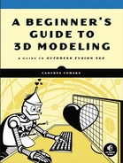
Even so, Fusion 360’s rendering capabilities are limited. It can certainly produce very nice renders that are more than sufficient for something like a Kickstarter campaign, but it lacks many of the tools found in software designed specifically with rendering in mind. If you need truly photorealistic renders of your model in complex scenes, you can always export your model as an STL file and open it in more advanced rendering software. Figure 9-1 shows a photorealistic scene created using 3D modeling and professional rendering software intended for creating visuals (as opposed to mechanical designs).
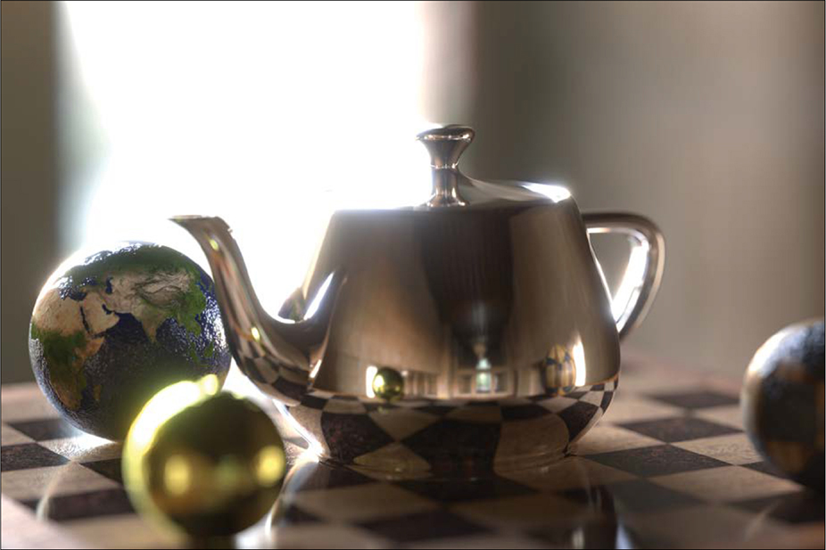
Figure 9-1: A photorealistic render created with professional rendering software
This book is focused on Fusion 360, so we’ll take advantage of the program’s built-in rendering capabilities to create a nice image of the screw we modeled in Chapter 7.
Rendering Your Screw
Go ahead and open the screw model. Right now, it should be a simple flat gray color, which is the default appearance.
There are two ways to change the look of the model. The first is by setting the Physical Material option, as you did with the brass hinge in Chapter 8. The second is to explicitly assign an Appearance setting, which overrides the appearance of the physical material. The appearance created by setting a physical material will apply to the entire model, but you can assign appearances to either the whole model or individual faces. You might want to give a solid model a two-tone paint job, for example.
In this case, the model is a regular old screw made from a single raw material, so set its Physical Material option to Stainless Steel, Polished. The model should look a bit nicer now; the color and reflections should look like polished stainless steel. But this is still a low-quality render, because Fusion 360 needs to keep the frame rate high so you can continue to work with the model. If the software were trying to produce high-quality renders continuously, it could take several seconds—or even minutes—to refresh every time you moved the model, rotated it, or modified it.
To dramatically improve how the model looks, switch over to the Render workspace. Immediately, you’ll notice that the model looks more realistic than it did in the Model workspace. Before we create our render, we need to make sure the screw is resting realistically on the ground and then prepare an environment to perform the render.
Making the Screw Rest on the Ground Plane
You may have noticed that the shadow on the ground plane doesn’t look right at all. The screw is just floating up in the air, which real screws don’t usually do. To place the screw on the ground, open the Scene Settings dialog from the main toolbar. Click the Position button to see the options shown in Figure 9-2. Change the Distance setting, which controls how far the ground plane is from the model, until the ground plane is just barely touching the screw.
Even though the screw head now touches the ground plane, the screw still doesn’t look right, because the threaded end is in the air, making the screw appear to balance on its head. That’s because Fusion 360 orients the ground plane so that it’s parallel with the bottom of the View Cube.
To fix that, we’ll need to reorient the screw in relation to the View Cube. Click Front on the View Cube at the top right of the screen in order to face the screw head on. Then use the Free Orbit option from the Display menu at the bottom of the viewport to rotate the threaded end of the screw down. At this point, the ground plane will rotate along with the screw, but when you’re done rotating the screw, you can fix this by right-clicking the View Cube, hovering over Set Current View As, and selecting Front (as shown in Figure 9-3).
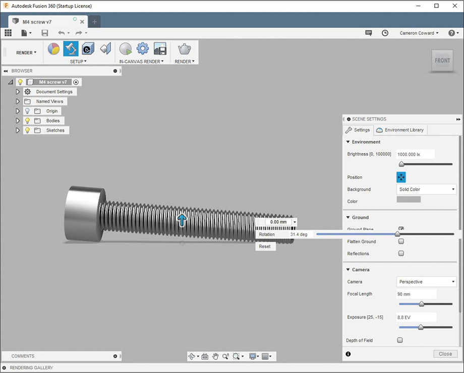
Figure 9-2: Position the ground plane so that it’s just barely touching the screw.
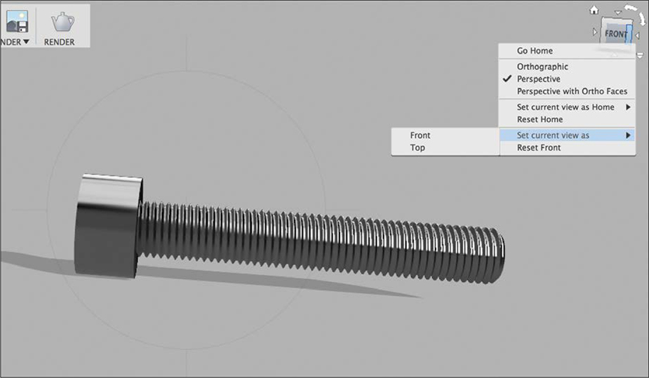
Figure 9-3: Rotate the screw to a resting position and set the view to Front.
After you’ve set the view as Front, the ground plane will rotate so it’s parallel to the new bottom view. Your screw may end up floating up in the air again, but you can adjust the distance to the ground plane if necessary. When you’re done, the screw should look like it’s resting on a real physical surface.
Setting Up the Environment
Next you need to set up the environment. Changing the environment does a few things: it positions light sources, provides a background and ground plane, and determines what reflections to show on the surfaces of the model.
If you open Scene Settings again, you’ll see a number of options for controlling how everything looks. Switch over to the Environment Library tab at the top of the dialog. There, you’ll find built-in environments, along with a few that you can download from Autodesk.
Some of the outdoor scenes provided make the model look like it’s in a real place, but most of the environments don’t show a background behind the model in your rendered image. Instead, most, like Cool Light and Photobooth, are there to give your model realistic lighting, shadows, and reflections.
Later in this chapter, you’ll learn how to place your model into a realistic scene, but for now, we’ll focus on making the model itself look good. Choose the Photobooth environment and then switch back to the Settings tab. The first option is Brightness in Lux. Adjusting this value will increase or decrease the brightness of the light in the scene.
The Position setting, as we’ve already covered, changes the height and rotation of the ground plane. The Background drop-down menu lets you use either the environment background or a solid color. For this render, use the Solid Color option with the default gray. Below that, you can turn the ground plane and reflections on or off. The Flatten Ground option only has an effect if you’re using an environment background, in which case it will make that background look less spherical.
Setting Up the Camera
The rest of the options in Scene Settings all relate to the settings of your virtual camera. Camera should almost always be set to Perspective, because this looks the most realistic. You could set it to Orthographic, which removes all lens distortion, but that’s not how humans actually see things, so I recommend avoiding this setting. Focal Length has the same effect as it does on a real camera: a longer focal length has less distortion and flattens the image, while a shorter focal length makes the image look highly distorted (like a fisheye lens).
Also as with a real camera, you can adjust the Exposure setting to change how long your virtual camera’s shutter remains open. This increases or decreases the overall brightness of the rendered image, instead of just altering the light sources with the Brightness setting. If you’d like, you can turn on Depth of Field to make the image lose focus the farther it gets from the center of focus.
The default settings are all fine here, but you can always adjust them if your rendered image is too dim or too bright. To prepare the image, close the Scene Settings and then click the Render button from the main toolbar and set Resolution to what you want your rendered image to be.
Performing the Render Operation
To finish, switch Rendered With to Local Renderer, which handles the computation on your own machine, instead of using the cloud-based Autodesk service. Autodesk provides a cloud renderer, but that requires credits to use. Use Final for the Render Quality setting and then click Render. Fusion 360 should then begin the rendering process, and a thumbnail should appear in the Rendering Gallery at the bottom of your screen. A progress bar should give you an approximation of how long the rendering process will take (in my case, it was about 30 seconds). Once it’s done, you can double-click the thumbnail to open up your final render (see Figure 9-4). Then you can save or share it.
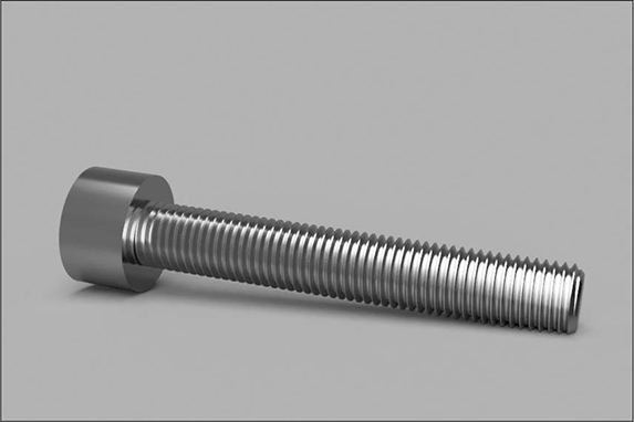
Figure 9-4: Your final render should look something like this.
This screw looks pretty good, but it’s made up of a single part. Most of your models will be assemblies consisting of multiple parts, and the more detailed your model is, the better the final render will look. The screw, for example, would look more realistic if the head edges had tiny fillets.
Next, let’s see how we can make a render look more realistic.
Rendering a Clock with a Decal Face
One of the best ways to make a model look real is to add decals, or 2D images. Almost every item you can purchase will have something printed on it, be it a logo, a warning diagram, or a button label.
To illustrate that concept, we’ll model and render an analog clock using a decal for the numbers on the clock face.
Creating the Clock Parts
To start, model the physical parts of the clock to look like what you see in Figure 9-5. The clock should have a total of six components: the frame, the hour hand, the minute hand, the second hand, a pin for the hands, and a clear plastic cover. Create these however you’d like.
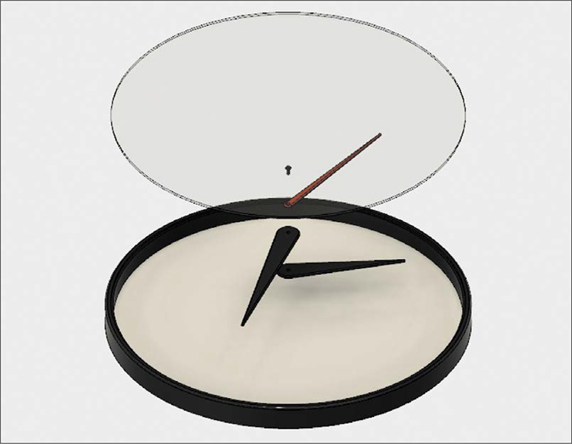
Figure 9-5: Model a clock with six separate components.
Next, assign a physical material for each part. The frame part will have two appearances: black plastic for the outer frame and white plastic for the face. After assigning the materials and appearances, use joints to lock them together. The hour, minute, and second hands should have cylindrical joints so that you can rotate them later to specific time settings.
Creating the Decal
Once you have modeled the parts, head over to Google and find an image of a clock face. Any image will work, but the higher the resolution, the better. That image will serve as the decal you’ll place on the clock face, and pixelation from a low-resolution image will seem unrealistic. Ideally, you’ll find an image with a transparent background to make it look like the graphics are printed directly onto the plastic face.
After you’ve found a suitable image, move over to the Render workspace to place it as a decal. Hide the clear plastic cover and click the clock face. Then, select the Decal tool from the main toolbar. For Select Face, choose the face of the clock, and for Select Image, choose the image you found. Turn off Chain Faces so that the decal isn’t wrapped onto the black plastic of the frame. Then adjust the size and position of the decal, as shown in Figure 9-6.
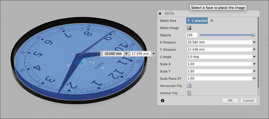
Figure 9-6: Select the face and the image and then position the decal.
Now that you’ve placed your decal on the clock face, you can set up the rest of the render. Move the hour, minute, and second hands so that they show the time you want; then show the clear plastic cover. Set Grid Light for the environment, because the harsh lighting will give the plastic cover some realistic light reflections.
Your Scene Settings should have Ground Plane, Flatten Ground, and Reflections checked. You can leave the camera settings at the default: 90 mm focal length and 9.5 EV exposure. Then just orient the model however you want it and create a final render. The result should look something like Figure 9-7.
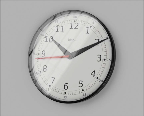
Figure 9-7: The final clock render should look pretty nice!
As you can see, adding a decal adds realism to the detail of a 3D model render, as do reflections on the clear plastic cover of the clock. But the clock is still just sitting on a plain background—a dead giveaway that you’re looking at a render.
Placing a Render in a Real Photo
To really sell the realism of a render, the best thing to do is place it in an actual photo. Ideally, you’ll choose a photo of a setting in which you’re likely to find your model.
To illustrate this concept, you’ll learn how to place a rendered Arduino Uno microcontroller development board into a real photo of a desk. I downloaded the 3D model of the Arduino Uno from Autodesk’s online gallery. Kevin Schneider created it, and it has a lot of detail. It even has labels on the capacitors. That detail is paramount to creating a photorealistic render.
Setting Up Your Background
To start, you’ll need to take a photo. Arrange the desktop scene you’ll place your model in. You’d likely use a real Arduino Uno with other electronics items, so for my background, I placed a soldering iron, breadboard, and other such items in the frame (shown in Figure 9-8). Before you take the photo, put some sort of placeholder on the desk to help you position the 3D render later on. I used a piece of paper that I cut to be slightly smaller than an actual Arduino Uno.
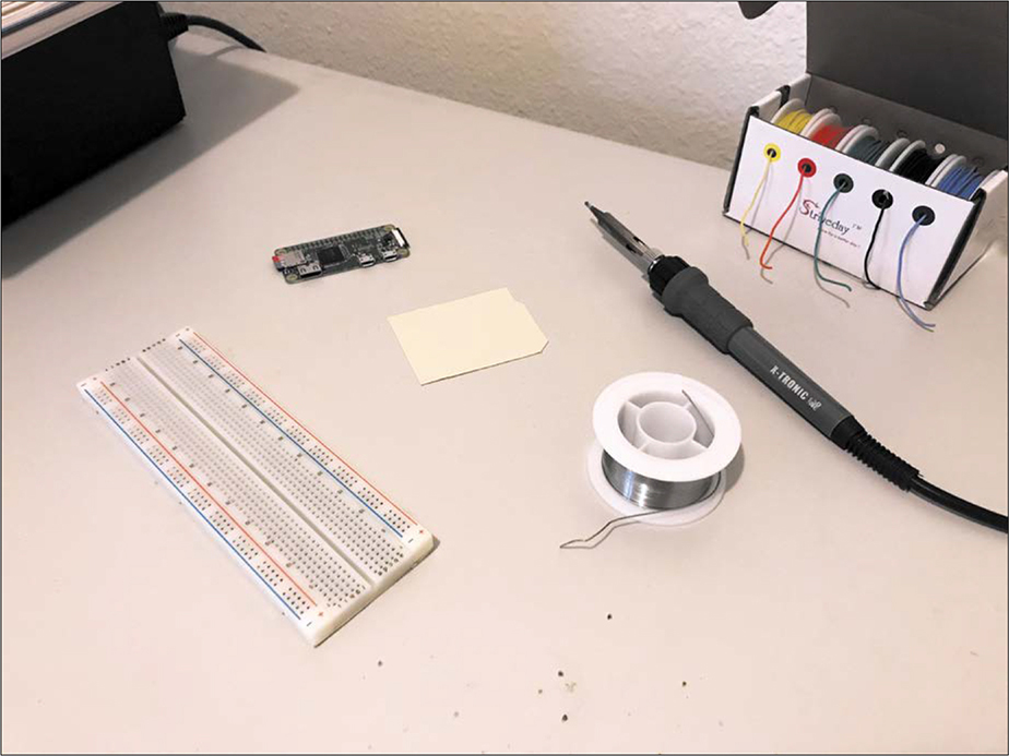
Figure 9-8: Set up your scene and add a placeholder for the Arduino Uno.
Once you’ve snapped the photo, bring your 3D model of the Uno into the Render workspace. If you downloaded the same model that I did, all of the detail (including decals) should already be there. Choose an Environment setting with lighting similar to the lighting in the room you took your photo in. Then use the Position Rotation angle to ensure that the light source is hitting the model at the same angle it would if it were actually in the photo.
Orienting Your Model
In the previous renders you created, the Camera settings weren’t all that critical. In this case, however, we want to make sure the lens distortion in the render matches that of the photo you took. The most critical parameter is Focal Length. You can find that information in the metadata of your photo, or possibly from your camera’s specs online if the focal length isn’t adjustable. In my case, I took the picture on an iPhone 7, which has a 35 mm equivalent focal length of 28 mm. You can see my Scene Settings in Figure 9-9.
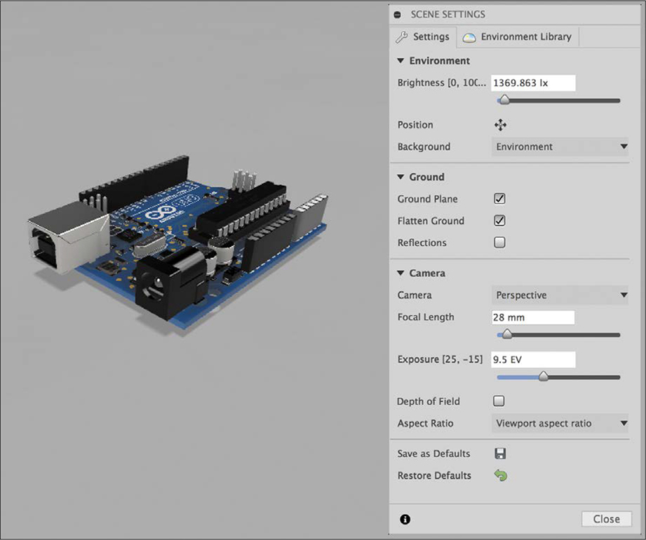
Figure 9-9: Change the Camera settings to match those of your actual camera.
Now orient the model to match the position it would have if it were really in the photo. Make the distance between the model and the camera the same as the distance in the photo you took. You need to match that distance both vertically and horizontally so the distortion of the render matches the distortion of the photo.
Once you’ve moved the model to the correct position, rotate it so that it’s at the proper angle. That’s where the placeholder you put in the photo comes in handy. It will help you tilt the model to the same orientation.
Getting the distance and angle just right can take a lot of trial and error, so for the next step, you may want to use low-quality renders until you’ve gotten the orientation right. You may need to create multiple renders, so making them lower quality will save time. When you create those renders, make sure you select the Transparent Background option.
Combining Your Images
The next step is to combine your rendered image with the photo you took. For that, I used GIMP (GNU Image Manipulation Program), which is a free and open source alternative to Adobe Photoshop. The particulars of using GIMP are outside the scope of this book, but you’ll learn the basic process next. (It should be roughly the same in other photo editors.)
Open both the original photo you took and the new rendered image you just created. Then copy the rendered image to a new layer on top of the photo layer. Next, position and scale the rendered image so it’s on top of your Arduino Uno placeholder. If the orientation doesn’t look quite right, adjust your model and render a new image. Repeat that process until your rendered image exactly matches the distance and tilt of your placeholder; then switch to a high-quality render with a high resolution.
You might need to adjust the color of both the rendered image and the original photo so that they match, paying particular attention to the white balance. Because the render has a transparent background, it doesn’t currently have a ground shadow. To add one, create a new layer under the render layer and over the photo layer and then use the Airbrush tool to paint a shadow on the new layer.
Once the rendered Arduino Uno looks like it’s part of the original photo—shadows and all—flatten the image to merge the layers.
Finally, add some photographic noise, or graininess, to the image. Your original picture almost certainly had a small amount of noise, but the rendered image doesn’t, which makes it stand out. A little bit of hue, saturation, and value (HSV) noise on top of the entire image will make it look more consistent. The final result should look like Figure 9-10.
Looks pretty decent, right? An image like this wouldn’t hold up to photo forensic scrutiny, but it does a much better job of making your model look like a real object than if the model were on a blank background. Taking the time to place your renders in a scene will help you picture your models in the real world and go a long way toward selling others on your ideas.
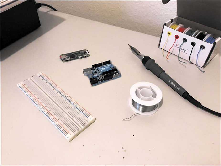
Figure 9-10: In your final image, the Arduino Uno should look like it’s really in the photo.
Summary
When you started this book, creating a simple cube was probably exciting. Now, you’ve developed a valuable skill set you can use to design complex 3D models, make technical drawings to have them manufactured, and even create photorealistic renders of your creations. Whether you’re using those skills to make 3D-printable replacement parts for your kitchen appliances or to design the next generation of high-tech robots, I hope you continue to practice what you’ve learned. But, before you go, I have one last exciting project for you in Chapter 10.