8
DRAFTING

In this chapter, we’ll cover drafting, which is the process of creating technical drawings. Ideally, you’d be able to send a file containing your 3D model off to a machine shop or manufacturer to have it made, but in the real world, that’s rarely sufficient. Some of the reasons for this are practical. The manufacturer might not use the same CAD software as you do, in which case they couldn’t even open your original model file. It’s also entirely possible that they won’t use CAD at all.
Manual machining is still very common; the manufacturer might not touch a computer when they make your part. Even if they do use CAD, many shops prefer to re-create a 3D model themselves using a system that works better with their machine tools.
But beyond practical concerns, the truth is that a 3D model alone doesn’t convey all of the information needed for manufacturing. A model like the one shown in Figure 8-1 only tells the manufacturer what the basic geometry looks like. Other details, like tolerances and surface finish, affect the part too, which is where technical drawings come in. For instance, if you want the shop to clean up the rough edges of a part after it has been machined, you would write “Deburr all edges” on a technical drawing to indicate that.

Figure 8-1: STL files like this convey the geometry of the part but not information on how to make it.
Don’t despair, though; drafting is pretty easy when you start with a 3D model.
Guidelines for Drafting
Formal drafting has hundreds of rules about everything from the thickness of different lines to the typefaces used for text. Luckily, in the real world, few people care about the vast majority of those rules.
For example, American National Standards Institute (ANSI) rules state that the text height for technical drawings should be 1/8 inch. That’s a good rule to follow if you remember it, but if you send a drawing to a manufacturer with a 3/16-inch text height instead, they wouldn’t reject the drawing. Drafting as a discipline is full of example s like that. There are rules and guidelines for every single detail of a technical drawing, but at the end of the day, what matters is that the people you send it to can easily and correctly interpret it.
In this chapter, we cover the parts of a technical drawing that impact a manufacturer’s ability to make your model. These aspects matter the most, and while there are many of them, Fusion 360 will create most of them for you. You just need to familiarize yourself with them so you’ll be able to check the quality of your drawings before you send them out.
Drawing Size
Drawings come in a variety of specific physical sheet sizes, which vary based on the standards the drawing is following. The big architectural blueprints you often see in pop culture, called Architectural E size drawings, are 48 inches by 36 inches, while a standard piece of 8.5-by-11-inch printer paper is called an ASME (American Society of Mechanical Engineers) A size.
That and the ASME B size (11 inches by 17 inches) are the most common, because they can go through regular printers and are easier to store and work with than larger sheets. I recommend sticking with ASME A size sheets, unless you have a good reason to use something else.
Scale
Scale, or the relationship between the size of your drawing and the size of the object, is one of the most crucial details of a technical drawing—and one that many novices overlook. Getting the scale right matters, because someone should be able to measure the drawing if they need to get information about the size of some part. If your part is 1 inch long and has a 1:1 scale, then it should be exactly 1 inch long in the drawing. The drawing would show the part as 2 inches long if you were using a 2:1 scale.
While that’s an easy concept to grasp, a few factors could end up making the scale of your drawing inaccurate. The most obvious of these is forgetting to note when different parts of the drawing have different scales. The drawing’s title block, in the bottom-right corner of the page, shows the drawing’s overall scale, which applies to every view unless otherwise stated. Sometimes, though, the drawing will show the same object from multiple views, and it’s commonplace for one view to have its own larger scale to more clearly show the detail of some feature.
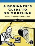
If an individual view scale differs from the scale of the overall drawing, you must note it in that view’s title. Fusion 360 will keep track of those scales for you in the views’ Properties dialogs, but you’ll have to type them into the text description of the views. The drawing in Figure 8-2 has an overall scale of 1:1, but one of its views has an individually set scale of 2:1.
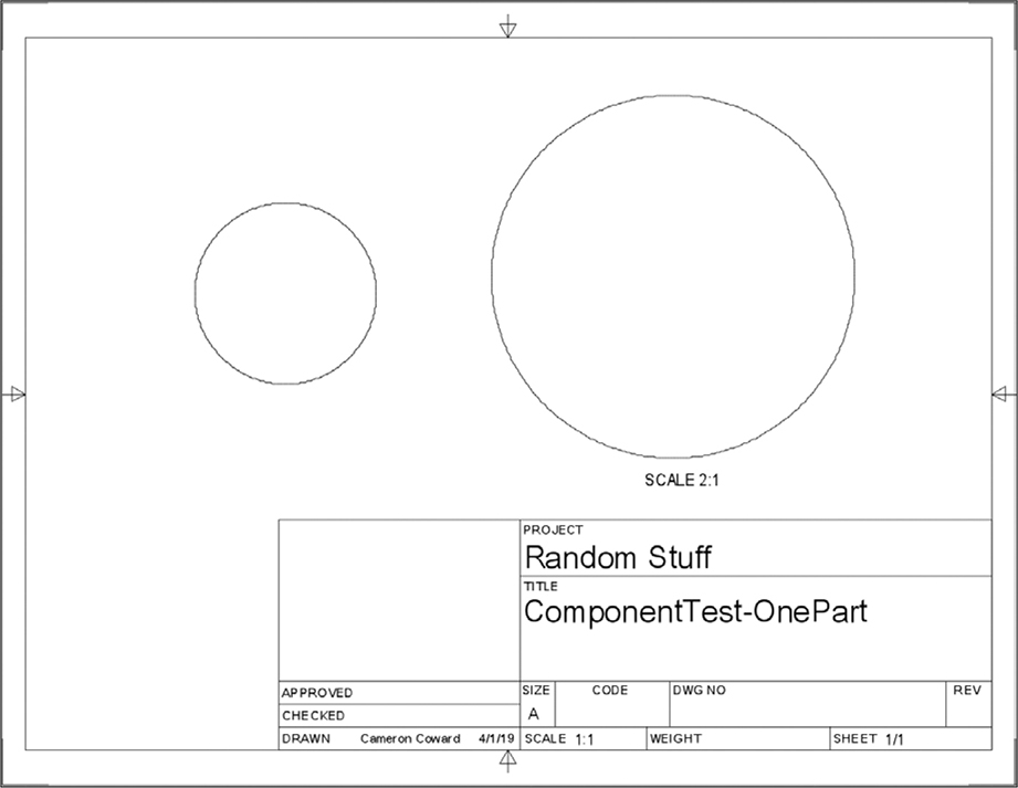
Figure 8-2: The view on the right has a scale that differs from that of the rest of the drawing.
Another common scaling mistake happens while printing a drawing or saving it as a PDF. On most computers, it’s pretty common for the print utility to automatically enlarge the document so it fills the entire page or reduce its size so it fits onto one sheet. That will throw off your scale, so make sure the software doesn’t do any scaling. You can do that by saving the PDF and printing it at “Actual Size.”
Projection Angle
Projections are views drawn using another view for reference. These date back to the days of traditional pen and paper drafting, when drafters would use straightedges to draw guidelines from one view to the next. They also give someone reading the drawing the ability to easily line up features between views. The projections remain locked into place with respect to the front view (the first view you draw) and must maintain the same scale.
The projection angle determines how to lay out your views in relation to the front view. You can choose between two options: First Angle Projection and Third Angle Projection. In a First Angle Projection (see Figure 8-3), the view to the right of the front view will show the part as if you were looking at it from the left side.

Figure 8-3: A First Angle Projection drawing
A Third Angle Projection (see Figure 8-4) will show the part as if you were looking at it from the right side.
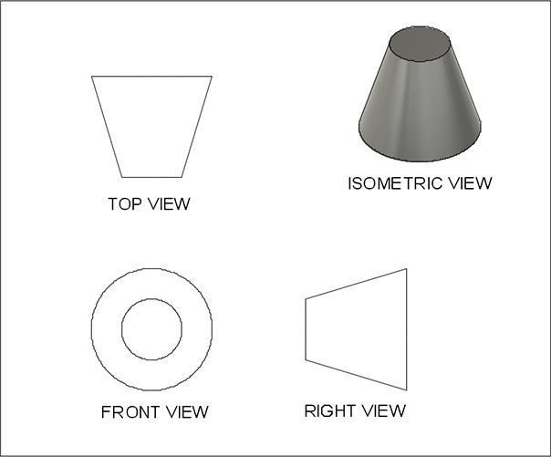
Figure 8-4: A Third Angle Projection drawing
The projection type you’re likely to come across mostly depends on where you are. In the United States and Australia, Third Angle Projections are the most common. The rest of the world generally uses First Angle Projections. I use Third Angle Projections in this chapter because I’m American and so was trained on them. The User Preferences window (shown in Figure 8-5) lets you change your projection angle or choose a default.

Figure 8-5: Switch your projection style in the User Preferences window.
ISO standards specify First Angle Projections, and ASME standards specify Third Angle Projections.
Tolerances
A tolerance tells the manufacturer how precisely it needs to adhere to the dimensions shown on your drawing (called nominal dimensions). You might have modeled a cube so each side is 50 mm long, but maybe the object doesn’t need to meet those measurements exactly. Even the world’s most high-tech manufacturing is imperfect; that’s just the nature of physical objects. Tolerance lets the manufacturer know how closely it needs to stick to your nominal dimension in order for you to accept the part.
Let’s say that 50 mm cube is a stand-alone toy. In that case, it’s not important for each side to measure exactly 50 mm, so you might specify a tolerance of ±0.1 mm. That “plus or minus” symbol tells the manufacturer that you’ll accept the part if the sides measure anything from 49.9 mm to 50.1 mm. That loose tolerance gives the manufacturer more flexibility in its machining options and makes it easier for parts to pass quality control, potentially lowering what you pay per part.
On the other hand, imagine that your cube has a 25 mm hole going through it where it will mate with the cylinder of a second part. In order to ensure the cylinder fits inside without leaving too much extra room, you might give the hole a much smaller tolerance of +0.01 mm, as shown in Figure 8-6. The machinist will then know that they can make that hole measure anything between 25 mm and 25.01 mm. They’ll know not to go below 25 mm, or the cylinder won’t fit.
Because tolerances can vary from feature to feature, you can specify them in two places: in the drawing notes or on the dimension itself. The tolerance in the notes is generally the loosest you’ll accept for the part as a whole. When a particular feature requires more precision (like the 25 mm hole), you can specify that in the individual dimensions.
Figure 8-6: The hole in the center of the cube has a tighter tolerance than the other parts.
Line Types
Finally, you’ll need to pay attention to the types of lines used throughout your drawings. Once again, Fusion 360 will create these for you, but you do need to know about a few of them, shown in Figure 8-7.
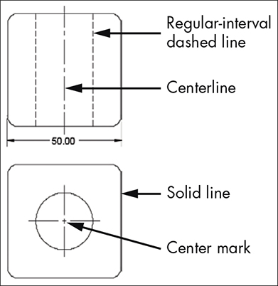
Figure 8-7: Line types in Fusion 360
Solid lines represent the edges you can actually see in that particular view. Regular-interval dashed lines show the edges of features that are hidden in that view, like those on the other side of the part. You don’t always need to show the hidden lines, particularly if the feature is clearly visible in another view. Too much clutter will make your drawing hard to read, so it’s a good idea to show hidden lines only if they’re actually helpful.
Certain special lines help illustrate the geometry of a part. The two most common are the centerlines and center marks on circular parts. You would use a centerline to show the axis of a cylinder and a center mark to show the centerpoint of a hole. Centerlines are usually staggered dashed lines, while center marks are crosshairs that extend just beyond the edge of the hole.
Drafting a Single-Part Drawing
There are two kinds of technical drawings: part drawings, which show the specific dimensions of an individual part, and assembly drawings, which show how multiple parts fit together. Although it’s possible to show part dimensions on an assembly drawing, you should avoid doing so, because the two kinds of drawings serve different purposes. Part drawings tell the manufacturer how to make each of your parts, while assembly drawings tell it how to put those parts together.
Every single one of your parts should typically have its own part drawing. The only exceptions are purchased parts, like bolts, washers, and electronics that you’re not making yourself. On the other hand, you only need to create an assembly drawing if you’re paying the manufacturer to put your creation together or filing a patent for your invention, in which case the patent office needs to see how it works.
We’ll make a part drawing for the hinge you created in Chapter 5. From the Project Browser, open the model part file (not the assembly file). Before you start the drawing, assign a physical material to your model using the Physical Material menu option under the Modify drop-down. Scroll down to the Metals section. Drag and drop Brass onto your model, as in Figure 8-8. That tells Fusion 360 the part is made of brass. It will use this information to calculate the part’s weight.

Figure 8-8: Choose Brass from the Physical Material menu and assign it to your part.
Now save the file and switch the Workspace to Drawing with the From Design option. A dialog should pop up. This gives you some basic options for the technical drawing. Choose the ones shown in Figure 8-9.
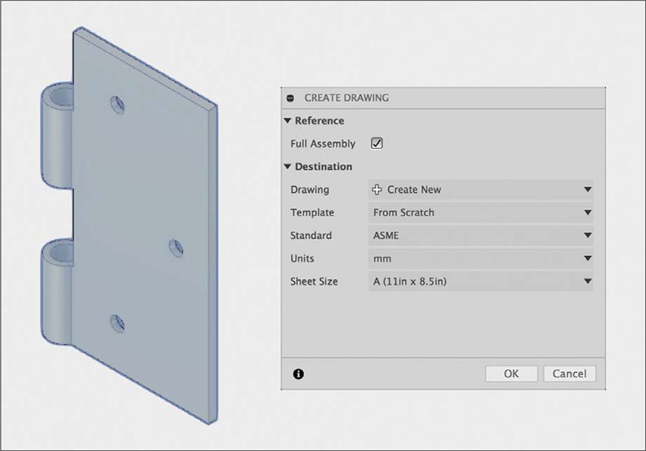
Figure 8-9: Your drawing options should look like this.
Leave Full Assembly checked; your file only has one part anyway. In the Drawing field, select Create New. You shouldn’t have any templates, so leave that field at From Scratch. We’ll make a Third Angle Projection drawing, so set Standard to ASME. In the Units field, select mm (millimeters) and set Sheet Size to A (11in × 8.5in).
Creating Your Views
Once you click OK, you should be taken to the Drawing workspace, and Fusion 360 should ask you to place the base view, which it will use to project the other views. The base view can show the part from any side you choose. However, for almost all drawings, you’ll want to use a front view for that and then project either a left or right view and either a top or bottom view. You want to choose views that clearly show all of the part’s features. Select Back from the Orientation drop-down menu, because that’s the side of the hinge half with the mounting hole chamfers. Otherwise, leave the default settings (shown in Figure 8-10) as they are.
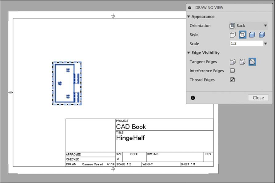
Figure 8-10: Use the back orientation for the base view.
With the base view placed, you can project a top view and a right view by using the Projected View tool from the toolbar at the top. Simply click the base view, click again to the right of the base view, and then click a third time at the top of the base view. Press ENTER. It’s best practice to place the projected views at approximately the same distance from the base view, as in Figure 8-11, so drag them around if necessary.
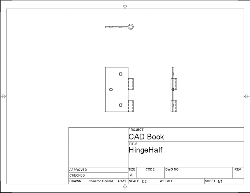
Figure 8-11: Place your right and top projected views at equal distances from the front view.
In Figures 8-3 and 8-4, I labeled the views to show you the difference between First and Third Angle Projections, but you don’t have to do that for standard drawings. If you’ve placed the views correctly, people in the industry will understand that these are front, right, and top views.
For simple parts like this, it’s also not necessary to use an isometric view, which shows the part from a three-quarter angle. Generally, you only need that view for parts where the geometry might not be clear from the standard three views. However, if you did want an isometric view, you’d simply add another properly oriented base view. You’d also need to label it and take care not to line it up with another view; otherwise, manufacturers might mistake it for a projected view.
Adding Center Marks and Centerlines
Once you’ve placed the views, you can begin annotating the drawing. First, place the center marks and centerlines. You can find these in the Geometry section of the main toolbar. Add center marks to any holes that appear head on and add centerlines to any hidden holes. When you’re done, your drawing should look like Figure 8-12.

Figure 8-12: Add center marks and centerlines to the holes in your drawing.
Adding Dimensions
Next, add dimensions to your drawing. When dimensioning a drawing, follow these guidelines: make sure you add enough dimensions to accurately define every feature, but avoid superfluous dimensions. If you’re unsure, always err on the side of having too many dimensions, but try to avoid cluttering your drawing with unnecessary information.
Standard conventions can help keep things concise. If you’ve duplicated multiple features (such as holes) in your model, you don’t need to specify the complete dimensions on each of them; just write “X3” next to the diameter of one hole. To indicate the diameter and angle of a hole chamfer, put the countersink symbol (∨) before your measurements. When two features are clearly aligned, you only need to add dimensions for one of them. Using Figure 8-13 for reference, add the dimensions to your drawing. You can double-click a dimension to edit it after it has been placed.
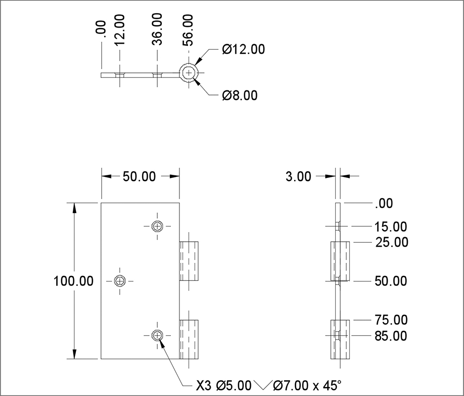
Figure 8-13: The drawing with all the necessary dimensions added
You may struggle with adding some of the dimensions, particularly the “X3 Ø5.00∨Ø7.00 x 45°” hole dimension and the two columns of dimensions that start with “.00”. The hole dimension requires that you edit the text itself. First, add the “X3” before the Ø5.00 that Fusion 360 gives you. Then, add the countersink dimensions by using the Insert Symbol tool from the dialog.
The lined-up dimensions in the top and right views are called ordinate dimensions. The “.00” signifies the starting point, and each of the other values indicates the feature’s distance from that point. To add ordinate dimensions, just choose the tool from the Dimensions part of the toolbar, select the starting point, then click each of the points you want to create dimensions for.
Ordinate dimensions make a drawing cleaner, less cluttered, and easier to read. They are also important for avoiding a problem called tolerance stacking.
As I mentioned earlier in this chapter, you should specify some amount of tolerance for every dimension to give the manufacturer wiggle room when it’s fabricating the part. But when the dimensions for one feature are based on those of another feature, the tolerances can add up. Look at the dimensions of the holes in Figure 8-14. Now, imagine those dimensions all have a tolerance of 0.1 mm.
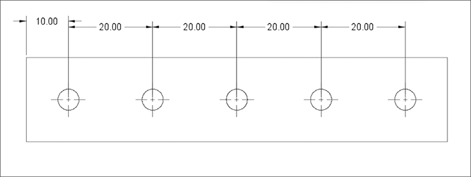
Figure 8-14: Tolerance stacking would make the rightmost hole have a huge variation.
If every distance were at its maximum tolerance, the hole on the far right could be as far as 90.5 mm from the left edge of the part. If every distance was at the minimum tolerance, that hole could be just 89.5 mm from the edge. That gives you a total variation of up to 1 mm, which might make your part unusable. Ordinate dimensions avoid tolerance stacking by using a single hard edge as a reference for each feature.
Adding Text
Now, with all your dimensions in place, you can round out the annotations by adding some notes, as in Figure 8-15. The first note indicates what kind of tolerance you’ll accept. The second note tells the manufacturer to deburr the edges after fabrication. To add notes, select the Text tool in the main toolbar.
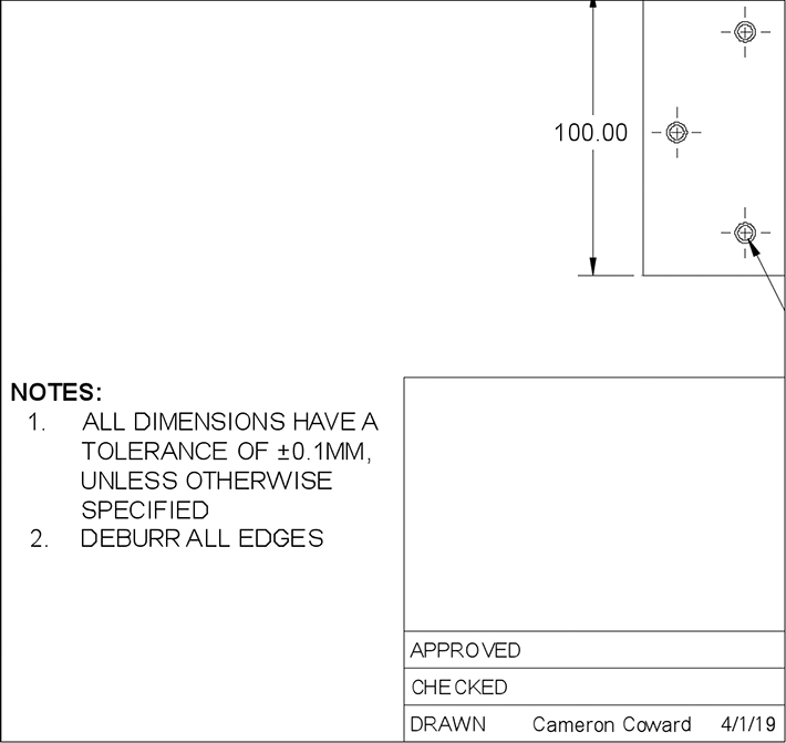
Figure 8-15: Add notes to your drawing to give the manufacturer important information.
The final step is to fill out the title block (shown in Figure 8-16), which contains details about the part and the drawing itself. Fusion 360 will automatically fill in some of the information, but you can edit it by double-clicking the title block. If you wanted to, you could place an image file for a logo in the top-left box. The Approved and Checked fields are for the internal document control processes many corporations follow; an engineering manager, for example, might use those to approve a drawing.

Figure 8-16: A typical title block
In the Drawn field, put the name of the person who created the drawing (you!) and the date it was drawn. In the Project field, you’d generally identify the assembly or subassembly the part belongs to, but there is no hard-and-fast rule about this; call the project whatever you want. In the Title field, write the name of your part. In the Size field, write the kind of sheet you are using (A, in this case). In the Code field, you can specify any regulatory codes that the part and drawing might adhere to. Unless you have reason to stick to a specific code, you can just leave that blank. The manufacturers will use the number in the Dwg No field to refer to the drawing internally and in their communications with you. You can use any number you like, but every drawing must have a unique number, and it’s a good idea to come up with some numbering conventions.
In the Rev field, which stands for revision, put a letter indicating which version of the drawing you’re using. Start with A, and any time you make a change to the drawing, advance to the next letter. If you get all the way to Z, start over with AA, then AB, and so on. Noting the revision is essential for ensuring that the manufacturer is working from the same drawing as you are. If you update drawing number 10021 to revision D, for example, your communications to the manufacturer might say something like “please reference drawing 10021-D.”
The Scale field shows the drawing’s overall scale. Fusion 360 will automatically set this to whatever you entered as the scale in your initial base view. If that changes, you should modify it in the title block to match. In the Weight field, put the weight of your part. To get that information, go back to your model. Right-click the top level of the Component Browser and check the properties. Finally, complex part drawings can have multiple sheets, so use the Sheet field to indicate which sheet this is.
Once you’ve filled out your title block, you’re done! You can then choose an option from the Output menu (usually PDF) to save the drawing. Remember, if you’re going to print your drawing, you must make sure to turn off scaling so it prints at its actual size.
Exercise
In this chapter, I walked you through how to create a drawing of a single part, but you’ll sometimes have to create assembly drawings, which illustrate how multiple parts fit together. Create one now from the complete Hinge Assembly. It should end up looking something like Figure 8-17.
You’ll have to create an exploded view of the assembly, which shows how the separated parts fit together. To do this, go to the Animation workspace, click Auto Explode from the main toolbar, and then save the assembly. If needed, you can reorient the model and save it as a new home view by right-clicking the View Cube. Then, when you create the drawing, choose the From Animation option to use that exploded view.
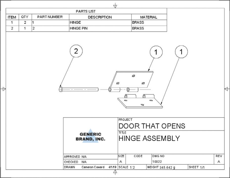
Figure 8-17: Your Hinge Assembly drawing should look like this.
You also have to add the bill of materials (BOM), which is a table at the top of the drawing that shows your parts list. To create that, choose Table from the main Drawing toolbar. Once you place the table, your parts will automatically populate it. Part Number, Description, and Material are all controlled by the properties accessible from the Component Browser in the Model workspace. Then just place balloons (from the same menu) to label each part in the drawing.
Summary
Technical drawings are very complex, and drafting as a profession takes years to master. Luckily, 3D CAD software like Fusion 360 has made the process a lot easier. Using the skills you’ve learned in this chapter, you should be able to create clear and professional technical drawings that real manufacturers can use to make your designs. In Chapter 9, you’ll learn how to make high-quality renders of your designs for presentations.