
6
Physical Layer Security
Simone Soderi1,2, Lorenzo Mucchi3, Matti Hämäläinen1, Alessandro Piva3, and Jari Iinatti1
1 Centre for Wireless Communications, University of Oulu, Oulu, Finland
2 Alstom Ferroviaria SpA, Florence, Italy
3 Department of Information Engineering, University of Florence, Florence, Italy
6.1 Introduction
Along with the rapid deployment of wireless communication networks, wireless security has become a critical concern. Unfortunately, security risks are inherent in any wireless technology. Some of these risks are similar to those of wired networks, some are exacerbated by wireless connectivity and some other are completely new. The most significant source of risks in wireless networks is that the communications medium is open to intruders. Mobile and handheld wireless devices are resource constrained (e.g. battery life) and hence such devices have limited transmission power and may use weaker cryptographic mechanisms for saving power, thereby making them easy targets for powerful adversaries. Self‐configuring heterogeneous networks may use very different levels of security, the lower secured links being a potential breach for the whole system. A direct consequence of these risks is the loss of data confidentiality and integrity and the threat of denial of service (DoS) attacks to wireless communications. Unauthorized users may gain access to system and information, corrupt the data, consume network bandwidth, degrade network performance, launch attacks that prevent authorized users from accessing the network, or use resources to launch attacks on other networks.
The security of radio interfaces of wireless networks is nowadays crucial for many applications: broadband internet, e‐commerce, radio‐terminal payments, bank services, machine‐to‐machine communications, health/hospital remote services, etc. In addition, the approaching sensing procedures of future radio access technologies such as white space and cognitive networks will result in numerous transmissions of precious geo‐referenced radio engineering data, whose integrity and confidentiality must be well secured.
Most commonly‐used security methods rely on cryptographic techniques, either asymmetric (based on public and private keys) or symmetric (based on a shared secret not known by others), which are located at the upper layers of a wireless network. Encryption does not protect from the undesired demodulation of the information by eavesdroppers, but only from the interpretation of the data as meaningful words. The cryptographic protocols base their security on the fact that, statistically, the amount of time for performing a decrypting analysis is enormous. The time to break a codeword is related to the computational power of the attacker, that is, cryptography intrinsically assumes that the eavesdropper has a limited amount of computational capability. Recent efforts of academia and industries to power up the amount of operations per second of the digital processors make this assumption weaker and weaker. Physical layer security does not make any assumption on the computational power of the attackers. Moreover, the standard practice of adding authentication and encryption to the existing protocols at the various communication layers has led to inefficient aggregations/mixtures of security mechanisms. Since data security is so critically important, it is reasonable to argue that security measures should be implemented at all layers where this can be done in a cost‐effective manner. This leads us to point out our attention to the first layer: the physical one.
6.1.1 Physical Layer Security in 5G Networks
Working on the next generation of wireless communications imposed the development of the security engineering as a multidisciplinary field. Nowadays, skills required for security range from cryptography and computer science to hardware and embedded systems [15]. Typically, security is implemented through cryptography at upper layers in the open system interconnection (OSI) model. In the past few years, several techniques based on signal processing have been utilized to secure communications at a physical layer and those are promising methods in the applications where standalone security solution is needed [21,23].
In this chapter, the authors focus their attention to the fifth generation (5G) networks’ security. 5G is expected to enable the hyper‐connected society, supporting the growth and the development in many sectors. These improvements leverage the deployment of new products also in critical infrastructure, such as railway and energy, in which a high degree of availability and dependability is required. On the other hand, this trend leads to an addtional exposure of the future mobile communications to cyber‐attacks that can undermine the system availability [28]. Security services included in wireless communications are authentication, confidentiality, integrity and availability [15]. The new security idea discussed here addresses countermeasures against the confidentiality attacks.
5G network shall serve as key enabler for future applications that use wireless technologies. Wireless communications beyond 2020 becomes pervasive, introducing the Internet of everything, in which many small devices interact with each other and with users. 5G systems will encompass different radio providing ultra‐high capacity, energy efficiency and new spectrum management solutions [24–26]. This evolution imposes the development of new security engineering methodologies and the appropriate mitigations, because these systems will have different wireless interfaces and their operating scenarios will include an extensive utilization of wireless links. Due to its nature, wireless communications might be vulnerable to eavesdropping attacks and this chapter propose the utilization of physical layer security techniques to 5G network.
6.1.2 Related Work
In the literature, there are several contributions that deals with a physical layer security because, due to their nature, wireless communications might suffer eavesdropping attacks. In 1949, Shannon defined the information theoretic metric for secrecy systems [1] and he proved the perfect secrecy condition where the eavesdropper cannot pull out any information from the transmitted signal. Afterwards, Wyner introduced a wiretap channel model defining a secrecy capacity as the maximum transmission rate that is achievable whenever the eavesdropper’s channel observations are noiser than the legitimate user’s channel [2,17]. Finally, Csiszár et al. extended Wyner’s results to non‐zero secrecy capacity when a non‐degraded wiretap channel is utilized [4]. This model includes a transmitter, Alice, a legitimate receiver, Bob, and a passive eavesdropper named Eve. Bob and Eve receive Alice’s transmissions through independent channels, as depicted in Figure 6.1, where tr indicates transmitter‐receiver link, te is the transmitter‐eavesdropper link, and je is the jammer‐eavesdropper link. As shown in Figure 6.1, we expanded this model, introducing a receiver with a jammer whose utilization is explained in the rest of this chapter.
Figure 6.1 Block diagrams of the proposed protocol to analyze physical layer security.
In the past few years, researchers exploited jamming as a fundamental part of original ideas for network security. More recently, a channel independent protocol named iJAM has been introduced [20]. The fundamental iJAM operating principle is shown in Figure 6.2. Alice, the sender, transmits two times each symbol and Bob, the receiver, randomly jams complementary samples over the two symbols. In this scheme, only the legitimate receiver knows which samples it jammed. Later, Bob is able to get a clean signal by discarding corrupted complementary samples from the original signal and its repetition. In contrast, the eavesdropper cannot remove the interference, because he does not have any information on the jamming characteristics [20].

Figure 6.2 iJAM’s operating principle.
6.1.3 Motivation
The primary goal of this study is to develop a new transceiver architecture to ensure secure communication combining watermarking with jamming receiver. As a performance metrics, authors utilize an outage probability of the secrecy capacity to evaluate the effectiveness of this secure communication. The proposed scheme is partially based on iJAM’s concept and the paper also provides the information theory analysis for the evaluation of this new approach.
Soderi et al. proposed the watermark‐based blind physical layer security (WBPLSec) as a valuable method to secure communication without neither assumptions on eavesdropper’s channel nor jamming from third‐party nodes [27]. In that paper, authors exploit the watermarking concept to increase system performance in terms of outage probability of secrecy capacity.
In the multimedia context, the digital watermarking process is utilized to hide or embed a desired signal into another signal, for example into pictures and videos. This process has a lot of similarities with traditional communications. Spread‐spectrum (SS) watermarking techniques are frequently utilized to implement physical layer security [22] and we adopt the second paradigm for watermarking described by Cox et al. [7], where the information to be embedded is modified prior to insertion, to exploit hidden data.
The truly innovative process for deploying a physical layer security consists of the steps showed in Algorithm 6.1.
The rest of this chapter is organized as follows: Section 10.2 describes the WBPLSec system model introducing transmitter and receiver architectures. Section 10.3 introduces the outage probability of secrecy capacity of a jamming receiver. Then, in Section 10.4, the application to 5G use case is presented. Finally, the chapter is concluded with Section 10.5.
6.2 WBPLSec System Model
The authors address the general problem of physical layer security presented in [13], in which any secure communications shall handle secrecy to avoid confidentiality attacks. The WBPLSec system model is shown in Figure 6.3, where the jamming receiver together with the watermarking provides secrecy. The selected watermarking technique provides the needed information destroyed with the jamming.

Figure 6.3 Non‐degraded wiretap channel model with jamming receiver.
In our study, a modified version of the non‐degraded wiretap channel model [4] is used. It includes the so‐called jamming channel utilized to jam the received signal and the eavesdropper.
The source message (xS)N of length N is encoded into code word ![]() of length N. In particular, the encoder embeds the watermark
of length N. In particular, the encoder embeds the watermark ![]() of length NW into the host signal (xS)N. The legitimate user, Alice, transmits
of length NW into the host signal (xS)N. The legitimate user, Alice, transmits ![]() to Bob through the main channel, which in this case is assumed to be a discrete‐time Rayleigh fading channel. The i‐th sample of the signal received by Bob is given by
to Bob through the main channel, which in this case is assumed to be a discrete‐time Rayleigh fading channel. The i‐th sample of the signal received by Bob is given by
where hM(i) and kJ(i) represent the main channel’s and the jamming channel’s complex Gaussian fading coefficients, nM(i) is the complex zero‐mean Gaussian noise, and xJ(i) denotes the jamming signal, which is generated by Bob.
Figure 6.3 shows how the eavesdropper, Eve, is capable of observing Alice’s transmission over an independent discrete‐time Rayleigh channel, that is, a non‐degraded wiretap channel. The i‐th sample of the signal received by Eve is given by
where hE(i) is the wiretap channel’s complex Gaussian fading coefficient between Alice and Eve, nE(i) is the complex zero‐mean Gaussian noise, and gJ(i) is the jamming channel complex Gaussian fading coefficient. It is assumed that all channels are quasi‐static fading channels, which mean that the channel gain coefficients remain constant during the transmission of a code word: hM(i) = hM, hE(i) = hE, kJ(i) = kJ and gJ(i) = gJ, ![]() .
.
6.2.1 Transmitter
In accordance with the data decomposition method proposed in Section 10.1, Alice conveys the information by means of two independent paths. The information is sent to the legitimate user by means of a narrowband signal. On the other hand, Alice also embeds a SS watermark in the host narrowband signal. The watermark conveys part of the information to the legitimate user, Bob, through a secondary channel.
In accordance with the framework presented by Cox et al. [6], the transmitter combines the original modulated signal with an SS watermark, with an embedding rule defined as
where xS(i) is the i‐th sample of the amplitude shift keying (ASK) transmitted signal, μ is the scaling parameter, and w(i) is SS watermark. Without loss in generality, in the rest of the chapter we use the direct sequence spread spectrum for watermarking. On the other hand, the same mechanism developed in WBPLSec can be implemented throughout orthogonal frequency division multiplexed (OFDM) signals. Corresponding to iJAM, the utilization of OFDM ensures the jammed samples are indistinguishable from the clean samples1.
The host amplitude shift keying (ASK) modulated signal xS can be expressed as
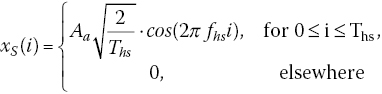
where Aa is the amplitude, Ths is the symbol time, and fhs is the frequency of the modulated signal. We propose as proof‐of‐concept the utilization of DSSS signal for watermarking as
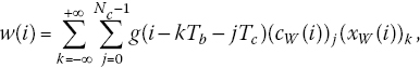
where (xW(i))k is the k‐th data bit of the watermark signal, (cW(i))j represents the j‐th chip of the orthogonal pseudo‐noise (PN) sequence, g(i) is the pulse waveform, Tc is the chip length, and ![]() is the bit length. The SS watermarking is shown in Figure 6.4, where cW represents PN code, which spreads the information, that is xW, that must be inserted in the host signal. With these assumptions, the energy of the watermarked signal is given by
is the bit length. The SS watermarking is shown in Figure 6.4, where cW represents PN code, which spreads the information, that is xW, that must be inserted in the host signal. With these assumptions, the energy of the watermarked signal is given by
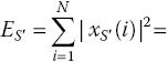

where ES is the energy of the xS signal and EW is the energy of xW. It is assumed that the host signal and its watermark in Equations (6.4) and (6.5) are uncorrelated.
Figure 6.4 Transmitter structure for watermark‐based blind physical layer security.
The signal watermarking is done by utilizing the traditional spread spectrum based approach [9]. The main idea implemented in the watermark embedding phase is that the transmitter marks, utilizing SS, the host signal xS utilizing its first NW over N samples. Then xW is given by

Alternatively, the receiver can jam NW discontinuous samples for each symbol, but even if this randomness requires a wide‐band jammer, for example ultra wideband (UWB), the work presented in this chapter is still valid. With ![]() , the energy of the watermark is given by
, the energy of the watermark is given by
Finally, the signal is mixed to carrier frequency fc and radiated by the antenna. Figure 6.4 shows the block diagram of the transmitter.
6.2.2 Jamming Receiver
In this chapter, the authors propose a different strategy to implement the jamming receiver’s architecture if compared to iJAM [20]. Indeed, the proposed scheme of the receiver works with jammed samples as well as the watermark extraction.
It is assumed that both the jamming signal and the host signal have the same energy over N samples as

Assuming N samples for symbol, as Bob jams M samples over N with ![]() , the energy of the jamming signal is given by
, the energy of the jamming signal is given by
The receiver structure is shown in Figure 6.5. In the WBPLSec, the legitimate receiver can jam at most ![]() samples, because NW samples are the information transmitted through the SS watermark. The received signal after the antenna is down‐converted to the baseband by the carrier frequency fc and then processed by the original signal demodulator to recover data exchanged through channel. Due to the jamming, the signal after the low pass filter (LPF), that is
samples, because NW samples are the information transmitted through the SS watermark. The received signal after the antenna is down‐converted to the baseband by the carrier frequency fc and then processed by the original signal demodulator to recover data exchanged through channel. Due to the jamming, the signal after the low pass filter (LPF), that is ![]() , is corrupted and unusable alone. To stitch unjammed samples and create a clean symbol, in parallel, the received signal is led to an additional DSSS demodulator used to recover the watermark xW. Afterwards, as in the iJam protocol [20], the receiver replaces corrupted samples in
, is corrupted and unusable alone. To stitch unjammed samples and create a clean symbol, in parallel, the received signal is led to an additional DSSS demodulator used to recover the watermark xW. Afterwards, as in the iJam protocol [20], the receiver replaces corrupted samples in ![]() with non‐jammed samples, which in our solution are taken from
with non‐jammed samples, which in our solution are taken from ![]() . In the end, the clean symbol xS is achieved and then demodulated.
. In the end, the clean symbol xS is achieved and then demodulated.

Figure 6.5 Receiver structure for watermark‐based blind physical layer security.
6.2.3 Secrecy Metrics
In Section 10.1, the authors presented the standard metrics used to measure the secrecy of communications. Regarding the notation used in Figure 6.3, Shannon defined a system that operates with perfect secrecy if the mutual information between the message (xS)N and the encoder output ![]() is zero [1]. This can be expressed as
is zero [1]. This can be expressed as
Together with the introduction of the wiretap channel, Wyner suggested the utilization of the weak secrecy, in which the amount of the information leaked about the message (xS)N by the eavesdropper when he observes (yE)N, is asymptotically zero [2], that is
Some applications cannot accept any information leakage and Maurer et al. defined the strong secrecy as follows [8]:
Strong secrecy is hard to design and weak secrecy preserves a practical interest [21]. The authors recall that the secrecy capacity of the legitimate link is defined as the maximum rate that is achievable with strong secrecy [3]. The objective of the physical layer security is to implement a reliable secure communication between Alice and Bob, at a target secure rate, leaking the least possible number of bits. Moreover, when the secrecy capacity is equal to zero, Alice can decide not to transmit, thus avoiding disclosure of any information. Reasonably, the authors selected the outage probability (Pout) to describe the secrecy capacity in the modified wiretap channel model depicted in Figure 6.3. Pout is defined as the probability that the secrecy capacity is less than a target secrecy rate ![]() [11].
[11].
6.2.4 Secrecy Capacity of WBPLSec
Win et al. [16] utilized a general wireless propagation model to characterize network interference in wireless systems. In accordance with that model, the received power, that is Prx, is ![]() , where Ptx denotes the transmitted power, dn, the distance between the two nodes and b is the amplitude loss exponent [10].
, where Ptx denotes the transmitted power, dn, the distance between the two nodes and b is the amplitude loss exponent [10].
The power spectra densities of the signals discussed above are illustrated in Figure 6.6. As shown in Figure 6.5, the received signal by Bob is split into two arms. The first part despreads and extracts the watermark. The latter filters the received signal to limit the bandwidth before the signal recovery [5]. The ideal LPF rejects a large fraction of the SS watermark and the magnitude of the residual watermark power density is given by

where ![]() is the bandwidth of the host signal, Tsa is the host signal symbol length,
is the bandwidth of the host signal, Tsa is the host signal symbol length, ![]() is the bandwidth of SS signal, and
is the bandwidth of SS signal, and ![]() is the processing gain.
is the processing gain. ![]() interferes the narrowband demodulator and Gp is defined as the inverse of the EW reduction factor [5].
interferes the narrowband demodulator and Gp is defined as the inverse of the EW reduction factor [5].

Figure 6.6 Power spectra densities of proposed blind physical layer security.
Therefore, the instantaneous signal‐to‐interference‐plus‐noise ratio (SINR) at the legitimate receiver, that is γM, is given by
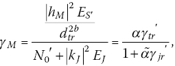
where both ![]() and
and ![]() follow an exponential distribution,
follow an exponential distribution, ![]() ,
, ![]() and
and ![]() . Due to the proposed jamming receiver architecture, the EJ does not undergo any attenuation at the legitimate receiver. Channels are power limited and it is assumed that
. Due to the proposed jamming receiver architecture, the EJ does not undergo any attenuation at the legitimate receiver. Channels are power limited and it is assumed that ![]() is the average transmit power, and
is the average transmit power, and ![]() is the average jamming power when Bob jams M samples over N with
is the average jamming power when Bob jams M samples over N with ![]() . Moreover, it is assumed that nM and nE have the same noise spectral density, that is N0.
. Moreover, it is assumed that nM and nE have the same noise spectral density, that is N0.
The instantaneous SINR at eavesdropper, that is γE, is given by
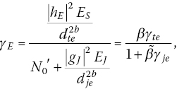
where both ![]() and
and ![]() follow an exponential distribution,
follow an exponential distribution, ![]()
![]() and
and ![]() .
.
When Bob has a better channel realization than Eve, that is ![]() , the secrecy capacity (Cs) of legitimate link is defined as follows for a non‐degraded Gaussian wiretap channel [4]:
, the secrecy capacity (Cs) of legitimate link is defined as follows for a non‐degraded Gaussian wiretap channel [4]:
where CM is the channel capacity from Alice to Bob, that is the main channel, and CE is the channel capacity from Alice to Eve, that is the wiretap channel exploited by the eavesdropper. Otherwise, if Eve has a better SINR than Bob, Cs is set to 0. In Equation (6.18), the author assumes that the noise plus the interference is still Gaussian.
In the presence of the Rayleigh channel, the secrecy capacity is conditioned to hM, hE, kJ, gJ, and without loss in generality in the rest of the chapter we impose ![]()
![]() [18].
[18].
The lower bound of the Cs is defined as the secrecy rate (Rs). Rs is given by the difference of the channel capacities from Alice to Bob and from Alice to Eve [2].
6.2.5 Secrecy Capacity of iJAM
In the iJAM, each symbol is transmitted twice. The receiver with jammer randomly jams complementary samples in the original signal and its repetition. The receiver knows which are the corrupted samples and then the clean symbol is achieved by stitching together unjammed samples.
The SINR at the legitimate receiver is given by [18]

where, in order to facilitate the comparisons between the two protocols, it is assumed to transmit the same energy, that is ![]() . When iJAM is utilized, the γE is still given by [17].
. When iJAM is utilized, the γE is still given by [17].
Figure 6.7 shows how in the iJAM the sender repeats its transmission and then halves the data‐rate when compared with the WBPLSec proposed here. In particular, iJAM has to transmit twice the same symbol to obtain a clean signal, whereas WBPLSec does not. The authors compared the metrics of iJAM and WBPLSec, assuming the same energy per symbol.

Figure 6.7 Comparison between iJAM and WBPLSec.
In the scenario of the iJAM and assuming that iJAM and WBPLSec have the same bandwidth, the Cs is given by
As in Equation (6.18), the ![]() is conditioned to the Rayleigh channel’s coefficients, that is hM, hE, gJ, and without loss in generality in the rest of the chapter, we impose
is conditioned to the Rayleigh channel’s coefficients, that is hM, hE, gJ, and without loss in generality in the rest of the chapter, we impose ![]() [18]. In Equation (6.20), the author assumes that the noise plus the interference is still Gaussian.
[18]. In Equation (6.20), the author assumes that the noise plus the interference is still Gaussian.
6.3 Outage Probability of Secrecy Capacity of a Jamming Receiver
The outage probability of the secrecy capacity is defined by Bloch et al. [13] as
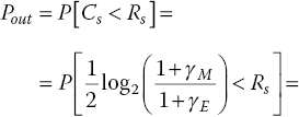

where Rs is the target secrecy rate, ![]() and
and ![]() . Therefore, in the case of WBPLSec, the results follow from simple algebra and can be expressed as [19]
. Therefore, in the case of WBPLSec, the results follow from simple algebra and can be expressed as [19]


where ![]() ,
, ![]() is the exponential integral. It is assumed that the fading channels’ coefficients are zero‐mean complex Gaussian random variables (RVs). The proof that α,
is the exponential integral. It is assumed that the fading channels’ coefficients are zero‐mean complex Gaussian random variables (RVs). The proof that α, ![]() , β and
, β and ![]() are exponentially distributed is given in Soderi et al. [28].
are exponentially distributed is given in Soderi et al. [28].
Figure 6.8 shows the outage probability of the Cs versus γM for different Eve’s positions. The eavesdropper moves along the line that connects Alice with Bob. The selected wireless propagation model accounts for far‐field propagation [16]. We considered the near‐field region limit at 1 m around Alice and Bob [18], as shown in Figure 6.8. With this model, Eve cannot be closer than 1 m to both Alice and Bob.
Figure 6.8 Outage probability versus γM when Eve moves from Bob to Alice.
In order to compare the proposed protocol against the iJAM, we computed the ![]() as
as
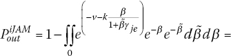
Figure 6.9 shows the comparison between the WBPLSec and the iJAM with equal energy per symbol, that is ![]() . Observe that the proposed protocol has better Pout than iJAM. On average, WBPLSec has Pout two times better than iJAM, comparing curves in Figure 6.9 with same EJ. Moreover, the higher is the EJ, the lower is Pout that yields to increase the performance of the proposed protocol. The scenario depicted in Figure 6.9 assumes Eve in the middle between Alice and Bob.
. Observe that the proposed protocol has better Pout than iJAM. On average, WBPLSec has Pout two times better than iJAM, comparing curves in Figure 6.9 with same EJ. Moreover, the higher is the EJ, the lower is Pout that yields to increase the performance of the proposed protocol. The scenario depicted in Figure 6.9 assumes Eve in the middle between Alice and Bob.
Figure 6.9 Protocol’s comparison of Pout versus γM for a selected Eve’s position.
Due to the jamming strategy implemented in the WBPLSec, Figure 6.10 shows the effect over Pout varying the number of jammed samples. Once more, the figure also depicts the Pout for the same scenario achieved with iJAM, that is when ![]() samples are jammed, that yields to have
samples are jammed, that yields to have ![]() . As illustrated in Figure 6.10, the more jammed samples per symbol exist, that is higher EJ, the less is the Pout. Thus, by controlling the value of EJ, the receiver can control the target secrecy level.
. As illustrated in Figure 6.10, the more jammed samples per symbol exist, that is higher EJ, the less is the Pout. Thus, by controlling the value of EJ, the receiver can control the target secrecy level.
Figure 6.10 Outage probability of the Cs versus γM varying the jamming energy when Eve is close to Bob.
6.3.1 Simulation Scenario for Secrecy Capacity
Table 6.1 lists the parameters used for simulations. For each distance of the eavesdropper among the transmitter and the jamming receiver, the Cs was simulated with a different number of jammed samples per symbol. The outage probability of the Cs was calculated, transmitting a watermarked signal with 50 dBJ energy. The watermark varies energy from 20 to 40 dBJ and a scaling parameter until 0.9. All the scenarios simulated refer to free space.
Table 6.1 Cs scenario parameters.
| Parameter | Value |
| dtr [m] | 10 |
| dje [m] | –15 ÷ 25[3] |
| dte [m][1] | 25 ÷ –15[3] |
| Number of samples (N) per symbol | 4096 |
| Number of jammed samples (M) per symbol |
256, 512, 1024 |
| Number of samples (NW) per watermark symbol |
1024 |
| 45 | |
| EW [dBJ] | 20 |
| Watermarking scaling parameter (μ) | 0.7, 0.9 |
| DSSS Processing Gain (Gp) | 16, 64 |
| AWGN spectral density (N0) [dBJ] | 3, 9 |
| Amplitude path loss exponent (b) | 1.0[2] |
| Secrecy Rate (Rs) | 0.1 |
[2] ![]() for free‐space
for free‐space
[3] Placing Alice at the origin of right‐handed coordinate systems and Bob at the distance positive axis, when Eve moves, also negative values occur.
In Figure 6.11, a comparison among three different eavesdropper’s positions are shown, that is, 1) Eve is close to Alice; 2) Eve is close to Bob; 3) Eve is in the middle. As illustrated in the figure, the more jammed samples there are per symbol, the less is the effect of the eavesdropper position.
Figure 6.11 Outage probability versus γM for different Eve’s positions.
The WBPLSec creates a security area around Bob. As shown in Figure 6.12, if Alice and Bob should implement a secure communication with a secrecy outage probability ![]() and
and ![]() dB, then Eve should not be close to Alice, that is the unsecured region is 5 m radius around Alice. Legitimate nodes, that is Alice and Bob, might tune ES and EJ implementing dedicated communication protocol strategies, for example a three‐way handshake, and then derive curves of Pout useful to define the needed security area. Furthermore, Figure 6.12 shows that with a lower γM, the security area is getting worse, because Eve should move away from Alice to achieve the same Pout. In Figure 6.12, Pout is plotted for two different values of γM, and for
dB, then Eve should not be close to Alice, that is the unsecured region is 5 m radius around Alice. Legitimate nodes, that is Alice and Bob, might tune ES and EJ implementing dedicated communication protocol strategies, for example a three‐way handshake, and then derive curves of Pout useful to define the needed security area. Furthermore, Figure 6.12 shows that with a lower γM, the security area is getting worse, because Eve should move away from Alice to achieve the same Pout. In Figure 6.12, Pout is plotted for two different values of γM, and for ![]() dB. It can be seen that the effect of increasing the jammed samples leads to a lower Pout close to Alice. Figure 6.12 also shows the near‐field regions around Alice and Bob.
dB. It can be seen that the effect of increasing the jammed samples leads to a lower Pout close to Alice. Figure 6.12 also shows the near‐field regions around Alice and Bob.
Figure 6.12 Increment of the M γ and its effect on the secure region size.
We have already shown that the secrecy outage probability depends on the eavesdropper position and on the number of jammed samples. In Figure 6.13, we have plotted Pout as function of the ratio ![]() for three different positions of Eve. Reasoning about the increase of EJ up to
for three different positions of Eve. Reasoning about the increase of EJ up to ![]() , the Pout is getting worse.
, the Pout is getting worse.
Figure 6.13 Outage probability as function of  .
.
6.4 WBPLSec Applied to 5G networks
Today, there are two standard practices to secure communications. The first approach adds authentication and encryption to the existing protocols. The second, which is also the approach selected by the authors of this chapter, embeds security technologies at the physical layer. In the context of 5G networks, physical layer security provides advantages when compared with cryptography techniques. The first advantage is that this technique does not depend on the computational complexity. In other words, the security level of the WBPLSec will not be affected, even if a user with high computation capacity would eavesdrop the secure communication. The second deals with the scalability, because any secure communication based on cryptography needs the cryptographic keys distribution and key management. In the case where many devices join and leave the network, that process is very challenging. Instead, the physical layer security can be used either to provide direct secure data communication or to facilitate the distribution of cryptographic keys in the 5G networks [29].
Figure 6.14 depicts how the WBPLSec can be applied to 5G networks. In accordance to the schema already presented in this chapter, the base station (BS), marked as Alice, sends the watermarked signal to the mobile terminal (MT), marked as Bob. We assumed that Bob has multiple radio interfaces to both receive and jam the received signal. The WBPLSec technique creates a secure region around Bob, in which any other MT, such as Eve, cannot eavesdrop the information.
Figure 6.14 WBPLSec applied to 5G network.
In the previous sections, we assumed isotropic antennas for all the stakeholders involved in the communication. On the other hand, future cellular network will exploit the smart antenna technology to improve the SINR to the legitimate receiver, Bob. Exploiting the smart antennas installed in the BS, Alice can enhance the directivity and the Bob’s SINR, as shown in Figure 6.15. This produces an advantage to Bob regarding to Eve and the secure region around will be wider.

Figure 6.15 Enhancement of the WBPLSec security region in the context of cellular network.
Any mechanism used to increment the γM to the legitimate 5G user, yields to the positive effect to increase the secure region, as shown in Figure 6.16. On the other hand, when ![]() , the security area becomes increasingly smaller up to disappearing. In such case, Alice and Bob cannot implement any secure communication.
, the security area becomes increasingly smaller up to disappearing. In such case, Alice and Bob cannot implement any secure communication.

Figure 6.16 Increment of the γM and its effect on the secure region size.
The WBPLSec can be successfully applied in those scenarios where mobile devices are equipped with several air interfaces. A definite upward trend in the number of air interfaces for each terminal has two defined possible approaches. At first, multi‐modality uses different chip solutions to implement air interfaces diversity. On the other hand, flexible air interfaces implemented via software defined radio (SDR) enables the opportunistic use of spectrum [12,23]. SDR is expected to play an important role of 5G networks, in which those air interfaces are applied to new architectures. The authors plan to leverage security and propose to use WBPLSec with SDR to support physical‐layer security solution in 5G devices.
6.5 Conclusions
The authors propose a technique, which is acting at the physical layer level, and not in higher layers, like the symmetric encryption protocol does. Basically, the goal is to improve the communication system compared to those with crypto‐protocols, in the same way as any other techniques that can fall into the definition of physical‐layer security. Physical layer security can be used together with and not in competition with the conventional cryptographic protocols. In the 5G of mobile networks, in which security shall be built into the system architecture, it is important to develop new techniques that implement standalone solutions, like the one proposed here. WBPLSec is a reliable physical layer solution against information disclosure attacks, such as eavesdropping. This solution is a trade‐off between security and communication reliability, because for fixed symbol energy, Es, increasing the jamming energy, EJ, a wider security area is achieved with a lower Pout. On the other hand, when EJ increases, the watermark extraction is getting worse with a higher Pe [27]. Furthermore, the proposed method exploits the non‐degraded wiretap channel without any assumption on Eve’s position and channel. One spreading code is utilized to implement SS watermarking. The wide utilization of SS communications makes the sharing of one PN code acceptable for this implementation. The WBPLSec shares the same information in terms of spreading code when compared with a, SS communication.
In comparison, with the iJAM, the proposed protocol offers the following advantages:
- it is a full‐rate protocol improving the major weakness of iJAM; and
- it has Pout two times better than iJAM.
The iJAM is an interesting protocol, but it implements a physical layer security with a split to half the data‐rate. The proposed scheme is an advanced version of iJAM. Both protocols utilize SS techniques, and even though the authors implement DSSS for WBPLSec, the same concept can be applied using OFDM, making the jammed samples indistinguishable from the clean samples. The worldwide proliferation of SS communication makes the utilization of a spreading code for physical layer security reasonable for both iJAM and WBPLSec. The utilization of SS watermarking yields WBPLSec to work full rate. Furthermore, the achieved results show how the proposed protocol can be a valuable technique for deploying security, creating a secure region around the legitimate receiver. The physical layer security is one of the most promising techniques for low‐power sensor networks and 5G devices. The avoidance of upper layers’ cryptography makes the physical layer security attractive as a standalone security solution that can also improve the battery life, because it saves computation when compared to encryption. Soderi et al. presented the lower energy consumption of the WBPLSec when compared with iJAM [27].
References
- 1 Shannon, C. (1940) Communication theory of secrecy systems. The Bell System Technical Journal, 28(4), 656–715.
- 2 Wyner, A. (1975) The wire‐tap channel. The Bell System Technical Journal, 54(8), 1355–1387.
- 3 Leung‐Yan‐Cheong, S. and Hellman, M. (1978) The Gaussian wire‐tap channel. IEEE Transactions on Information Theory, 24(4), 451–456.
- 4 Csiszar, I. and Korner, J. (1978) Broadcast channels with confidential messages. IEEE Transactions on Information Theory, 24(3), 339–348.
- 5 Peterson, R.L., Ziemer, R.E. and Borth, D.E. (1995) Introduction to Spread Spectrum Communications. Prentice‐Hall: Englewood Cliffs, NJ.
- 6 Cox, I.J., Kilian, J., Leighton, F. and Shamoon, T. (1997) Secure spread spectrum watermarking for multimedia. IEEE Transactions on Image Processing, 6(12), 1673–1687.
- 7 Cox, I.J., Miller, M. and McKellips, A. (1999) Watermarking as communications with side information. Proceedings of the IEEE, 87(7), 1127–1141.
- 8 Maurer, U. and Wolf, S. (2000) From weak to strong information‐theoretic key agreement. Proceedings of the 2000 IEEE International Symposium on Information Theory, p. 18.
- 9 Malvar, H. and Florencio, D. (2003) Improved spread spectrum: a new modulation technique for robust watermarking. IEEE Transactions on Signal Processing, 51(4), 898–905.
- 10 Goldsmith, A. (2005) Wireless Communications. Cambridge University Press: New York.
- 11 Barros, J. and Rodrigues, M.R.D. (2006) Secrecy capacity of wireless channels. Proceedings of the 2006 IEEE International Symposium on Information Theory, pp. 356–360.
- 12 Fitzek, F. and Katz, M. (eds) (2007) Cognitive Wireless Networks: Concepts, Methodologies and Visions Inspiring the Age of Enlightenment of Wireless Communications, Springer, Dordrecht, The Netherlands.
- 13 Bloch, M., Barros, J., Rodrigues, M. and McLaughlin, S. (2008) Wireless information‐theoretic security. IEEE Transactions on Information Theory, 54(6), 2515–2534.
- 14 Jeon, H., Kim, N., Kim, M., Lee, H. and Ha, J. (2008) Secrecy capacity over correlated ergodic fading channel. Proceedings of the IEEE Military Communications Conference, MILCOM 2008, pp. 1–7.
- 15 Anderson, R.J. (2008) Security Engineering – A Guide to Building Dependable Distributed Systems, 2nd edition. Wiley, Indianapolis, Indiana, USA.
- 16 Win, M., Pinto, P. and Shepp, L. (2009) A mathematical theory of network interference and its applications. Proceedings of the IEEE, 97(2), 205–230.
- 17 Bloch, M. and Barros, J. (2011) Physical‐Layer Security: From Information Theory to Security Engineering. Cambridge University Press, New York.
- 18 Rabbachin, A., Conti, A. and Win, M. (2011) Intentional network interference for denial of wireless eavesdropping. Proceedings of the 2011 IEEE Global Telecommunications Conference (GLOBECOM 2011), pp. 1–6.
- 19 Vilela, J., Bloch, M., Barros, J. and McLaughlin, S. (2011) Wireless secrecy regions with friendly jamming. IEEE Transactions on Information Forensics and Security, 6(2), 256–266.
- 20 Gollakota, S. and Katabi, D. (2011) Physical layer wireless security made fast and channel independent. 2011 Proceedings of the. IEEE INFOCOM, pp. 1125–1133.
- 21 Harrison, W., Almeida, J., Bloch, M., McLaughlin, S. and Barros, J. (2013) Coding for secrecy: an overview of error‐control coding techniques for physical‐layer security. IEEE Signal Processing Magazine, 30(5), 41–50.
- 22 Li, X., Yu, C., Hizlan, M., tae Kim, W. and Park, S. (2013) Physical layer watermarking of direct sequence spread spectrum signals. Proceedings of the IEEE Military Communications Conference, MILCOM 2013, pp. 476–481.
- 23 Soderi, S., Dainelli, G., Iinatti, J. and Hamalainen, M. (2014) Signal fingerprinting in cognitive wireless networks. Proceedings of the 2014 9th International Conference on Cognitive Radio Oriented Wireless Networks and Communications (CROWNCOM), Oulu, pp. 266–270.
- 24 Politis, C. (2015) 5G – on the count of three … … paradigm shifts. In: 5G Radio Technology Seminar. Exploring Technical Challenges in the Emerging 5G Ecosystem, pp. 1–29.
- 25 Zhang, H., Dong, P., Quan, W. and Hu, B. (2015) Promoting efficient communications for highspeed railway using smart collaborative networking. IEEE Wireless Communications, 22(6), 92–97.
- 26 I CL, Han, S., Xu, Z., Wang, S., Sun, Q. and Chen, Y. (2016) New paradigm of 5G wireless internet. IEEE Journal on Selected Areas in Communications, 34(3), 474–482.
- 27 Soderi, S., Mucchi, L., Hämäläinen, M., Piva, A. and Iinatti, J. (2017) Physical layer security based on spread‐spectrum watermarking and jamming receiver. Transactions of Emerging Tel. Tech., 28(7), June 2017.
- 28 Horn, G. and Schneider, P. (2015) Towards 5G security. Proceedings of the 4th IEEE International Conference on Trust, Security and Privacy in Computing and Communications (TrustCom).
- 29 Yang, N., Wang, L., Geraci, G., Elkashlan, M., Yuan, J. and Di Renzo, M. (2015) Safeguarding 5G wireless communication networks using physical layer security. IEEE Communications Magazine, 53(4), 20–27.