The idea of a journey is all very Zen, but we feel that it describes the fact that most engineers view self-improvement as a large motivational factor. The overall destination may be to build the perfect software and to be loved and admired by our peers. Along the way we have smaller destinations—finish a project, learn a new software tool, improve our productivity, and reduce stress levels. We also like the idea of having fellow travelers. Another important consideration we would like to emphasize is that we are still on our journey, and “perfect” is a very elusive destination, so any help from our fellow travelers would be greatly appreciated.
A project is like a journey as well; some projects can be akin to traveling uphill in mud! Successful projects have a clear destination, a carefully planned route, a map, a compass, and recognizable milestones along the way. Unsuccessful projects have no destination, an unclear destination, or a destination that moves faster than you do. Unsuccessful projects also have inadequate and inaccurate directions or, in the worst case, no directions at all.
This chapter will put meat on the bones of the previous chapters by applying what we've been discussing to an example project. We'll take our project from the very start and discuss along the way the common issues encountered. We'll demonstrate how to apply the techniques discussed in the preceding chapters. Along the way we'll highlight the areas where projects often go bad and discuss why. The demonstration software used in this chapter could be used as a pattern for your own project. We've certainly used it for ours.
Most projects start with an inquiry and an initial meeting to discuss your customers' requirements. Even if you are working internally within a company it doesn't exclude you from having customers such as your manager or the end user, for example.
First, get down to basics by listening to what your customer wants and then telling the customer what to expect. Each party understands exactly what the other party is talking about.
To get the ball rolling then, listen to what your customer wants. Right from the start the project can take a wrong turn, your customer could call you and you could do everything over the phone. Following is a list of ways you could undermine your project's chances of success at an early stage:
The customer should have an idea about the destination, and before setting out you should be able to confirm with the customer at least the general direction. So, if you're lucky there will be a requirements specification. Here's an example.
This document is usually accompanied by an initial requirements meeting. If no requirements document is made available prior to this, one should be discussed and produced from this meeting.
Now Derek has got to awake from his slumber and respond to the question from Millicent. He has various options; here are a few:
Yeah, LabVIEW can cope with anything you throw at it.
The problem here is that a bluff nearly always gets overtaken by reality. The other problem is that you are giving the customer the go-ahead to make changes without any consideration. Go this way, and you'll end up having end of project blues.

We will need a complete specification before we can begin. Changes later on are far too expensive to rectify and will weaken the design of the software.
For languages like C or Pascal this is a reasonably valid path to follow, because if using these languages, the developer will disappear for three months and reappear with a finished product. This can be a recipe for customer disappointment if the requirements are not concisely and accurately defined and understood by all concerned parties. LabVIEW gives the advantage of Rapid Prototyping, use it!
You also have to consider that the only constant in software projects is change. As your customers learn more about the system they will have more suggestions and comments. It's a fact of life and we all have to cope with it. A large amount of work will pass you by with this attitude because in business customers don't want to wait.
Finally, a decent language combined with a robust design strategy will allow flexibility at a reasonable cost.

LabVIEW is the language for writing the application, and the design of the application can be flexible or not. This depends on the effort put into the design and the inherent complexity of the system. We should design the system with flexibility in mind, but obviously there will be a cost consideration for large system changes. As long as the basic requirements stay the same we can reevaluate the process at each milestone.
We will also need to ensure that changes in requirements are communicated in an efficient manner and that only one person in your organization communicates them to us.
Go for it Developer man!
Anyway, we've chosen option 3 and the meeting continues.
The next step after the requirements have been communicated, is for you to tell what the customer is going to receive. This could be in the quote, contract, or as we like to call it, the target specification, and it should be regarded as your promise to the customer.
This is a communication-intensive process, so be prepared to talk to your customer. For example, it's a rare event when you get a requirement specification with no gaps in it. In this case there is little mention of the data to be collected by the system. Call them and clarify before you quote!
Accompanying the target specification should be the test plan. This will be the instrument for confirming that the destination has been reached.
Finally, we suggest the use of a prototype to better elicit requirements. However, this is usually only realistic at the requirements stage if the project has a separate cost feasibility stage. Alternatively, this can also be done as part of the design process to fine-tune the requirements. For your own sanity be prepared. Even if your software eradicates poverty from the world there will be someone who complains about the font!
Without a target specification your customer will not have confidence in what he or she is getting, and without a test plan the project will have no closure. You know what you are producing and your customer knows what he or she wants. A project will only be successful if everyone agrees.
So to summarize, the target specification should describe the key functionality of the system, and the test plan should list the tests that will establish that this functionality has been met.
In our journey these documents are the backpack, walking boots, food, compass, and map.
NO NO NO NO NO NO NO NO NO NO NO NO!
This is like embarking on a journey armed with unclear directions, no map or compass, and a vague idea of your destination.
We don't suggest you go down this road, since death and pestilence will be your traveling companions.
Noun Parse of Requirements Specification | |
Noun | Noun |
Widget | Analog Output port |
Widgetometer | Visual Inspection |
Test system | Calibration |
Test specification | Test position |
Display (Widgetometer) | Active test position |
Output Port (Widgetometer) | Customer test specification |
RS232 Communications | Part number |
Standard Widget | Data |
Test ports | Printout |
Reading | UUT |
Communication port | |
Noun Parse of Target Specification | |
Noun | Noun |
Main Display | Part number |
Central Display Area | Time of Test |
Control Buttons | Issue |
Dialog | Software Version |
Units Under Test | An Out |
Test Type | Serial Out |
Unit Details | Display Out |
Serial Ports | File |
Test Report | Directory Structure |
User Name | |
Date of Test | |
Serial Number | |
There are a few hidden components that most systems will need. For example, for this ATE there is no mention of the display and how it should look. A phone call confirms that the customer would like to see the test status and unit details on a screen.
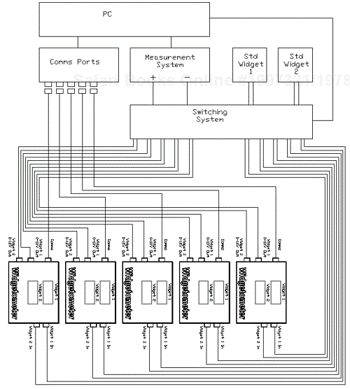
We can also have a look at the hardware design to swipe a few ready-made components. For example, there is a digital multimeter (DMM) for taking the measurements, a Switching System for making the connections, and a PSU (power supply unit) for providing power. Now you can try to disregard repeats and obvious components that are outside the system.
So, let's go through our list and collate what we have identified into a smaller set of nouns, deleting those that we don't need:
Nouns | |
|---|---|
Widget | |
Widgetometer | Discard—is not meaningful for ATE |
Test system | |
Test specification | Discard—not part of system |
Display (Widgetometer) | Put in Hardware |
Output Port(Widgetometer) | |
RS232 Communications | |
Standard Widget | |
Test ports | |
Reading | |
Communication port | |
Analog Output port | |
Visual Inspection | |
Calibration | |
Test position | |
Active test position | Discard—replace with Test Position |
Customer test specification | Discard—not part of system |
Part number | |
Data | |
Printout | |
UUT | |
Main Display | Replace with Display |
Central Display Area | Replace with Display |
Control Buttons | Replace with Display |
Dialog | Replace with Display |
Units Under Test | |
Test Type | |
Unit Details | |
Serial Ports | |
Test Report | |
User Name | |
Date of Test | |
Serial Number | |
Part number | |
Time of Test | |
Issue | Discard—relates to documentation |
Software Version | |
An Out | Discard—same as Analog Output Port |
Serial Out | Discard—same as RS232 |
Display Out | Discard—same as Widgetometer display |
File | |
Directory Structure |
From our table we can see that some nouns have been discarded, but others have been replaced with (we think) a more meaningful description—Display.
Customer test specification and test specification are obviously referring to the same thing, so drop customer test specification because the system will not care who owns the specs.
There's also an argument that test position and active test position are similar enough to be ignored. Active could be an attribute of test position perhaps.
All right, our next job is to group the nouns under a heading.
Data | Hardware | Test System | Report | Display |
|---|---|---|---|---|
Test Report | Widget | Visual Inspection | Printout | Display |
User Name | Output Port | Calibration | Control Buttons | |
(Widgetometer) | ||||
Date of Test | RS232 Communications | Test position | Dialog | |
Serial Number | Standard Widget | Part number | ||
Part number | Test ports | UUT | ||
Time of Test | Reading | Units Under Test | ||
File | Communication port | Test Type | ||
Directory Structure | Analog Output port | Unit Details | ||
Software Version | Test position | Serial Ports | ||
Widgetometer display |
We have grouped each of our nouns under a heading that collectively describes it. This should be our starting point for the highest level components. More than one design can solve a problem, and you could have dissected the nouns differently and still come up with a decent design. For our example though, we have decided that our table headings now represent the main components in our system.
Putting it all together we will have a display that is populated by readings taken from the test system component. This test system will consist of a hardware component that will model all the states of the hardware. The hardware component will be responsible for talking to the serial communications, the DMM, and the visual inspection system. The results will be stored by a data component and printed by the report component. The component interaction diagram will look like Figure 9.2.
Now at the top level we can define the actions for each component.
This component describes the abstract things that the display will be required to do.
Reset Display
Show Test Position
Update Test Position
Update Status Area
This will be a state machine that will run through each test for each unit, checking pass-fail criteria and distributing the results data. So as well as the individual tests there will be states that model initialization, storing data, checking status, error states, and printing reports.
Any individual action for the hardware is modeled by this component. This is at the highest level of abstraction.
Initialize
Measure UUT Channel 1 An Out
Measure UUT Channel 2 An Out
Read UUT Channel 1 Serial
Read UUT Channel 2 Serial
Read UUT Data Serial (this is Serial Number, Part Number, etc.)
Get UUT Channel 1 Display
Get UUT Channel 2 Display
Any output to any printer is handled by this component. At this stage there is only one report required.
Initialize
Print Report
All test data is held here. This component has the responsibility for loading test limits and settings as well as storing and archiving the test results.
Command | Attribute |
|---|---|
Initialize | Measure Error % |
Load Test Settings and Limits | Read Error % |
Store Test Results | Display Error % |
Get Limit | Measured Value 1 (An out) |
Set Result | Measured Value 2 (An out) |
Read Value 1 (Serial) | |
Read Value 2 (Serial) | |
Read Value 1 (Display) | |
Read Value 2 (Display) |
This component handles anything to do with the configuration data. The attributes will be set during development.
Load All
Save All
Load
Save
Get
Set
This component sets up the configuration data and anything else that needs initializing.
At this stage the top-level components are doing very broad, abstract operations. The language of the commands is very specific to the test system. The components that these top-level components employ will become more and more specialized the farther down the program hierarchy they are.
Okay, this is a bit contrived, and since design is a gray area there will be other ways of doing it. Practice has shown us that using these techniques does throw up similar designs again and again. Patterns are a way of taking advantage of these prefabricated designs.
There are two design patterns that we can employ here. If it looks as though the system is going to have a lot of individual displays, then we suggest starting off with the Menu Tree Pattern. If any of the displays are complex and require information from subVIs to be passed and displayed, we suggest using the UI Controller>>Message Queue Pattern for each.
This system doesn't require a large number of displays and therefore doesn't merit a menu-submenu system, but the complexity of the data to be displayed on the main UI does warrant the use of the UI Controller>>Message Queue Pattern.
First, let's reach a consensus about what the general UI operation is going to be.
A meeting is called with the main protagonists attending:
There has been a lot of information floating about, so Derek now writes the following on his sketch.
Initialize>>Set Up Display>>Run>>Finish
These are fairly repeatable from system to system. The other common state for the system could be a general error state where the program goes if it all goes horribly wrong.
Action | Description |
|---|---|
No Action | Just ignore |
Disable Position | Disables the selected position |
Enable Position | Enables the selected position |
Position Visible | Makes the selected position visible |
Position Invisible | Makes the selected position invisible |
Update Position Data | Updates the data for the selected position |
Update Instruction Display | Sends text to the Instruction display |
Set to Tests Not Started | Sets the display to the not started state |
The beauty of separating the actions like this is that you can design the basics of the system and implement them for the prototype without getting bogged down in detail. You know that the User Interface will react to the commands even though the actual contents of the Unit Data areas have not been established yet.
Position Number (1 . . . 5)
This is a useful technique for simplifying the interface. Derek could have described the system fully by having lots of UI actions. For example, he could have had Disable Position 1, Disable Position 2, . . . Disable Position X. There is a potential problem in that the customer could come back and say that for cost purposes he or she wants to test 10 units. While not a showstopper, it could become cumbersome to have to write in all the commands for each unit.
Test Not Started>>Enter Data>>Testing>>Tests Complete
There will also be a Test Executive defined as part of the Testing State. We'll come back to this when we have the Test Specification of the Widgetometer.
We now have an idea of the User Interface, so let's tackle the hardware.
Back to the meeting.
UnderRange
Read Unit Status
Read Unit Serial Number
Read Unit Part Number
Read Unit Software Version
Read Chan1 Reading
Read Chan2 Reading
Get Chan1 An Out
Get Chan2 An Out
Get Chan1 Display Reading
Get Chan2 Display Reading
OverRange
The Hardware component actions are now defined and there is a list of jobs that need doing. Using the Control >>Drive>> Read Pattern we can break down the components further (although this is not necessary for the purpose of the meeting).
Unit Number (1 . . . 5)
Some customers haven't thought that deeply about what they want. It is also often the case that they don't fully understand what they want until they get it. This happens frequently, so we recommend the use of a prototype to demonstrate the User Interface interactions.
In LabVIEW, building a prototype is not necessarily expensive, and if you use patterns you can use the prototype as the basis for your main program. The idea of a prototype is to emulate the look and feel of how you envision the program working. Therefore, the User Interface should be functional to the extent that buttons can be pressed and data displayed. There shouldn't be any connections to the hardware at this stage. You shouldn't spend much more than one to two days putting the prototype together.
Another small bit of advice given to us by an ISO9000 auditor is “always feed them something,” by this we mean deliberately leave something out or leave an obvious gap. In the auditor's case it was a ploy used by those being audited to distract. In our case we can use it to generate customer involvement, or to get customer “buy in” and start the conversion. We have found that people begin to accept the design more readily if they feel that they have contributed to it in some way. We should try to animate each step in the program—remember it is a demonstrator for the customer.
—Transfer of User Interface Pattern
Download and extract the examples from the Website. Copy the “UI Controller-Message Queue Pattern” directory in its entirety to a new directory called “C:WidgetometerSoftware.” In the directory, Widgetometer Test SystemSoftware1 Displays1 Main Display, change the name of the User Interface.vi to Widgetometer User Interface.vi. It is also a good time to change the Window Title for this VI.
—Design your User Interface
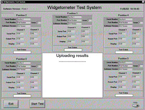
Dump all the controls and indicators onto the Front Panel and tidy up, as shown in Figure 9.3.
From the requirements document it was established that there would be five test positions. This was the limit of what could be displayed completely on the screen, without having to resort to summary screens. A Strict Type Def. cluster was created that held all the data for each unit under test. Copies of this cluster were distributed around the screen and titled Position 1–Position 5. Using a Strict Type Def. cluster will allow you to make changes to all of the clusters at the same time. The central area was allocated for instructions and test details and is just a plain string. Finally, the [Exit] button was left as is and [Button2] was renamed [Start Test].
Before we go on to actually emulating the running of the test, let's look at what basic actions we require from the User Interface.
User Interface Basic Actions
Each position cluster will need to be updated, enabled, disabled, and made visible or invisible.
For every [Start Test] button there should be a [Stop Test] button.
The [Exit] button should be disabled during a test.
[Button3] should be made invisible, since there is no apparent use for it yet.
Following are the User Interface Actions that came with the pattern:
Action | Description |
|---|---|
Underrange | Throws or passes error |
Clear Queue | Clears the queue of display actions |
Get Display | Gets the next display item off the queue |
Enable Button 1 | as action |
Disable Button 1 | as action |
Enable Button 2 | as action |
Disable Button 2 | as action |
Button 2 Visible | as action |
Button 2 Invisible | as action |
Enable Button 3 | as action |
Disable Button 3 | as action |
Overrange | as Underrange |
Button 1 is the [Exit] button for our User Interface and the action should be updated to reflect this. Button 2 is the Start/Stop Test Button and, as well as renaming the button, we need further action to change the button text. Button 3 needs the visible-invisible actions.
We need to list new actions for the position clusters—these will be update, enable, disable, visible, and invisible. We should leave the UnderRange, OverRange, Get Display, and Clear Queue actions alone since they are always used.
The new User Interface Actions will need to be put into the Display Command.ctl and the Display Setting.ctl. Just open, edit, and save each control.
Display Command.ctl | Display Setting.ctl |
|---|---|
Underrange Error | No Display |
Clear Queue | Enable Exit Button |
Get Display | Disable Exit Button |
Enable Exit Button | Enable Start Stop Button |
Disable Exit Button | Disable Start Stop Button |
Enable Start Stop Button | Update Start Stop Button Label |
Disable Start Stop Button | Enable Button 3 |
Update Start Stop Button Label | Disable Button 3 |
Enable Button 3 | Button 3 Visible |
Disable Button 3 | Button 3 Invisible |
Button 3 Visible | Enable Position |
Button 3 Invisible | Disable Position |
Enable Position | Position Visible |
Disable Position | Position Invisible |
Position Visible | Update Position |
Position Invisible | Update Inst Screen |
Update Position | |
Update Inst Screen | |
Overrange |
Create a Strict Type Def. enumerated control that models the test position, and its values should be:
Underrange, Unit 1, Unit 2, Unit 3, Unit 4, Unit 5, Overrange
Save it as Test Position.ctl and use it everywhere.
The UI queue component will have the Test Position.ctl as both input and output, and it will also pass it as part of the message queue. The adjustments to the UI queue component are relatively straightforward.
Open the UI Queue.vi.
Select the Test Position control using the “Select a Control . . .” button on the Control Palette.
Drop it into the Input box and copy it to the Output box.
Change the Test Position.ctl in the output box to an indicator.
Copy and Paste the Test Position control into one of the Local Store Clusters. This is a Strict Type Def. and will need to be opened and the Test Position control pasted into it.
Wire the input and output connector terminals.
Finally, wire the input and output controls onto the block diagram.
The result should be something like Figure 9.4.
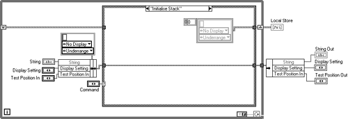
The cluster constants seen in the diagram in Figure 9.5 are instances of the Strict Type Def Queue Items.ctl, and any changes to it are reflected in changes to the diagram.
Figure 9.6 shows the UI controller component that acts as a wrapper for the UI queue component. Once again we'll need to add the Test Position.ctl as both input and output and wire them to the connector. If you open up the diagram, you'll notice that the source has changed to reflect the new values for the instances of Display Setting.ctl and Display Command.ctl. Spooky!
The Test Position.ctl will need wiring into and out of the case structure and connecting to the UI queue component where required. In this case it is only required as an output from the Get Display>>More Items?=True case. See Figure 9.7 for the wiring diagrams.
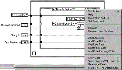
Now we need to add the new cases to correspond to the elements in Display Command.ctl. This is a simple matter of selecting a suitable case and right-clicking and selecting Duplicate Case from the pop-up menu as shown in Figure 9.8.
The new case will automatically take on the name of the next element in Display Command.ctl, which in this case is “Enable Position.” This case needs to be aware of the test position, so it will need Test Position wiring into the UI queue component. See Figure 9.9 for wiring of additional cases.
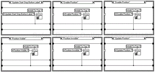
Finally, we need to make each action work! Look at the Control Display While Loop on the Widgetometer Test System block diagram in Figure 9.10. Right-click on the case structure and select Add Case for Every Value. Now you have a set of pigeonholes awaiting their actions. All of these actions are simple attribute settings, except for Update Position, and we'll tackle that later.
Here's the code for the Control Display While Loop as shown in Figure 9.10.
Figure 9.11 shows examples of the cases filled out. You will need a case for every action.
Now if you load a Test Stub VI called UI Display Stub.vi, and run the Widgetometer User Interface, you will be able to test the changes that have been made. The UI Display Stub.vi simply places messages on the message queue, and these are actioned by the User Interface. Now we are ready to give the prototype some life.
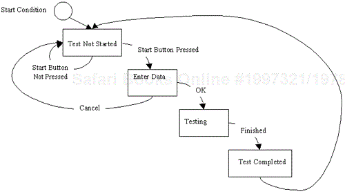
On starting, the program will settle into its first state: Test Not Started. When the start button is pressed, the Enter Data state is activated. After successfully entering data, the Testing state is started and the sequence of tests are run through. When the tests are done, the Tests Complete state is entered and any posttest actions finished.
A flexible approach is to produce a simple component that drives the program executive states. Figure 9.12 demonstrates how.

This component stores the required program executive state locally, by the “Set Test State” command, and returns it once on a “Get Test State” command. All we need to do now is have a loop checking the Test State and acting when it changes, and we have ourselves a nice, flexible program executive. We'll add the loop to the Widgetometer User Interface VI and put in some functionality, or the “Enter Data State.” A simple Enter Data dialog box was created, and if you notice the Monitor Control Buttons loop on the diagram in Figure 9.13, you'll be able to see that when button 2 [Start Stop Test] is pressed, the Test State is set to Enter Data. When the Program Executive loop next iterates, it will retrieve that state and action it.
Inside the Enter Data dialog will be the code that decides what step to go to when the dialog exits. If it exits on a Cancel the next state should be to return to Test Not Started. If the dialog exits successfully then the next state would be Testing. In a similar fashion to decoupling the User Interface actions from the front panel, we've now decoupled the Program Executive actions. We now have the freedom to control the way the Test Sequence runs from nearly anywhere in the software hierarchy.
Now we can proceed on our journey with the confidence that we have done everything possible to extract information from our customer. The customer in turn should have some confidence that the project about to be received will make him or her truly thankful.
So, onward.
Looking closer at the hardware pattern, we've already defined the top-level commands for the component, so now we'll go deeper. Each hardware action is a combination of Control, Drive, and Read. There may be no need for all of them, but at least one will be required. For instance, a simple thermometer would only have the Read component, whereas a scanning thermometer would have a combination of Control and Read.
Here's the implementation for this project and a reminder of the actions for this component.
It transpires that the power is switched on to all the units at the start of the test and removed at the conclusion of testing. This means that two extra hardware actions are required to apply and remove power to the units.
So, here are highlights from the source code.
Action | Description |
|---|---|
UnderRange | Throws or passes error |
Initialize System | Sets up all the hardware components |
Switch STDs In | Connects the standard units to the selected test position |
Reset Switches | Clear connections |
Read Unit Status | Read the selected unit's Status from the serial port |
Read Unit Serial Number | Read the selected unit's Serial Number from the serial port |
Read Unit Part Number | Read the selected unit's Part Number from the serial port |
Read Unit Software Version | Read the selected unit's Software Version from the serial port |
Read Chan1 Reading | Read the selected unit's reading for channel 1 from the serial port |
Read Chan2 Reading | Read the selected unit's reading for channel 2 from the serial port |
Get Chan1 An Out | Measure the selected unit's channel 1 analog output |
Get Chan2 An Out | Measure the selected unit's channel 2 analog output |
Get Chan1 Display Reading | Get the display reading for channel 1 |
Get Chan2 Display Reading | Get the display reading for channel 2 |
Power On | Apply power supply to units under test |
Power Off | Remove power supply from units under test |
OverRange | As UnderRange |
Looking at Figure 9.14 you can see that Test Position is a Strict Type Def. enumerated type that has already been defined for the prototype and is used throughout the software. Hardware Actions is a new Strict Type Def. enumerated type that has all the actions that were defined earlier.
Hardware Actions has been set to “required” as a precondition, and a standard wiring pattern has been defined, as shown in Figure 9.15 and 9.16. All components will follow this pattern where possible.
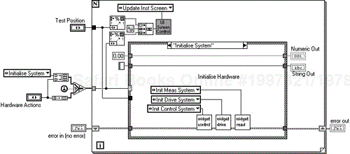
The block diagram looks like that shown in Figures 9.17. The first time through the hardware is initialized.
The UI screen control is sent a message describing each action that has been taken by the hardware component. The hardware action is then implemented. The actions that talk to the serial ports are all pretty repetitive and involve sending the message and the unit position for that message to the read component. This will then do all the communicating and return a string or numeric value. The measure action is a bit more involved; it requires a bit of switching to select the unit under test.
Clearly demonstrated here is the self-documenting nature of LCOD—you can see exactly what each component is being asked to do.
Programming the Get Chan2 An Out action was simply a matter of duplicating the Get Chan1 An Out case and changing the command to the control component as shown in Figure 9.18. The Power On and Power Off commands use the drive component and simply set the power supply volts to 24 or 0 as shown in Figure 9.19.
The hierarchy in Figure 9.20 shows the Control>>Drive>>Read pattern. Below the generic Switch, DMM, and PSU components would be the manufacturers or your own drivers. For continuity we tend to rewrite them as components as well.
It is envisioned that the measurement and signal lines are switched from the units under test to the computer and measurement equipment.
Action | Description |
|---|---|
UnderRange | Throws or passes error |
Init Control System | This initializes the control hardware, getting and setting identifiers and setting initial conditions |
Reset Switches | Set all switches open |
Switch Standards In | Switches the standards into the chosen position |
Switch DMM to Chan1 | Switches the DMM to channel 1 of the chosen position |
Switch DMM to Chan2 | Switches the DMM to channel 2 of the chosen position |
OverRange | As UnderRange |
Here's the implementation.
So regarding Figure 9.21 we will define Control Commands as a Strict Type Def. enumerated type and use Test Position as in the hardware component.
As we go to lower levels of abstraction we can see the commands becoming more oriented to the hardware. This is demonstrated by the states in Figures 9.22 and 9.23 that are now less identifiable as part of a test system and more specific to switching systems.
Drive is used for signal injection, PSU setting, and similar actions. For this project there is a requirement to switch on the power supply to the Widgetometer.
Action | Description |
|---|---|
UnderRange | Throws or passes error |
Init Drive System | This initializes the drive hardware |
Set PSU Volts | Sets the power supply volts current |
Get PSU Volts | Returns the power supply volts |
Get PSU Current | Returns the power supply |
Clear PSU | Sets the power supply to a safe level, 0 Vdc |
OverRange | As UnderRange |
The front panel, as shown in Figure 9.24, is a command Strict Type Def. enumerated type, with just the voltages in and results out.
The rest of the states are the same, as shown in Figure 9.25, with corresponding messages to the PSU component.
There will be a multimeter for analog input measurement. There will also be the commands to talk to the serial port. Finally, we'll put the visual inspection stuff in here as well.
Action | Description |
|---|---|
UnderRange | Throws or passes error |
Initialize Meas System | This initializes the measurement hardware |
Read Unit Status | Read the selected unit's Status from the serial port |
Read Unit Serial Number | Read the selected unit's Serial Number from the serial port |
Read Unit Part Number | Read the selected unit's Part Number from the serial port |
Read Unit Software Version | Read the selected unit's Software Version from the serial port |
Read Chan1 Reading | Read the selected unit's channel 1 reading from the serial port |
Read Chan2 Reading | Read the selected unit's channel 2 reading from the serial port |
Get Chan1 Display Reading | Get the display reading for channel 1 |
Get Chan2 Display Reading | Get the display reading for channel 2 |
Measure Analog Out | Returns the dc volts from the DMM |
OverRange | As UnderRange |
Let's quickly look at some of the implementation of these actions.
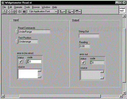
Figure 9.26 shows the Read component front panel, where once again we use the ubiquitous Test Position Strict Type Def. enumerated type, and as before we define a new Read Commands Strict Type Def. enumerated type with the commands defined earlier.
Nothing too tricky about this. The read component merely calls the visual, serial, or DMM components and returns their responses as shown in Figures 9.27 and 9.28.
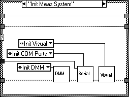
The only other action of note is the Initialize command, which is shown in Figure 9.29.
Finally, you need a test executive, so that is discussed next.
The array of hardware actions drives the For Loop for each active test position. In reality, the results would go to a file or a database. The more observant reader will have looked at Figure 9.30 and noticed that the array “Tests” is an array of constants. Correct! Although they are dynamic Strict Type Defs., they are indeed constants and would be better placed in a file.
If you see a constant String or Number anywhere in your code, pull it out into a configuration file. We use a pattern for this that takes advantage of the flexibility of enumerated types.
Make a copy of the Prototype Software Directory on your hard drive and rename it Widgetometer Software Directory. Now you need to copy the configuration directories over to where the program resides. So copy the following directories to your Widgetometer Software Directory:
....PatternsSection Keyed Data Handling Pattern1 Displays
....PatternsSection Keyed Data Handling Pattern2 System
If this has been done correctly, you will find that the following message will be displayed as shown in Figure 9.31.
Select [Yes to All].
Rename the directories to suit as shown in Figure 9.32.
Open Widgetometer User Interface.vi and find any lost VIs. Widgetometer User Interface loses Widgetometer Enter Data.vi and 2 button dialog.vi. Then select File>>Save With Options>>changed VIs from the menu and save everything.
Without closing Widgetometer User Interface.vi, open Config ini.vi and as before find any lost VIs or Controls. This is usually just Datamanager.ctl. Once again select File>>Save With Options>>changed VIs from the menu.
Rename Config ini.vi to Widgetometer Config ini.vi, and update the icon to reflect the new program.
Now we need to open the configuration file when the program starts and load all the configuration data. In Widgetometer User Interface.vi you will find UI Initialize.vi, open it up and put . . .\2 System2 Data Handling1 File Management1 File HandlerFile Handler.vi into it, and put in the file path to the configuration file as shown in Figure 9.33.
Also put in the two data manager VIs. They can be found in . . .\2 System2 Data HandlingConfig Data (or copied from the hierarchy diagram). Pop up on the command input and select “Load All”.
Now drop Widgetometer Config.ini into the case for Button 3 in Widgetometer User Interface.vi diagram (run state), as illustrated in Figure 9.34.
You can optionally change the names of the data manager files and customize the icons to your individual requirements. What you now have is the capability to create, load, and save constants in a reasonably secure location. Defining these constants is as simple as updating an enumerated type control.
Let's do a couple as an example. Let's remove the example parameters and add a new parameter called System Name. We've changed the data manager names to Widgetometer System Config Data Man.vi and Widgetometer System Config Data Man2.vi.
Double-click on the parameter control on Widgetometer System Config Data Man.vi front panel to bring up the control editor (if you haven't got this option set you'll have to open the control in longhand by highlighting the control and selecting customize from the menus). Figure 9.35 shows the resulting screen.
Remove the example parameters and replace the last one (you won't be able to remove it) with System Name.
To run the new set up you will have to ensure that the directory for the Config.ini file exists (as pointed to in UI Initialize.vi). The ini file will be automatically created when the program is first run.
Now run Widgetometer User Interface.vi and select Button 3 (after it moans about there being no file). The Config.ini dialog should be displayed. You will notice that there is now a key called System Name.
Other constants we could pull out of the code at this stage are:
Power Supply On Volts
Power Supply Off Volts
Serial Port Settings (baud rate, handshaking protocols and data, and start and stop bit sizes)
All you do then is drop the Widgetometer System Config Data Man.vi into the relevant hardware VI and wire it as shown in Figure 9.36.
Finally, the array of Strict Type Def. enumerated types used to drive the Test Executive should also be generated from the configuration file.
In keeping with the components within components theme we have created an error handling component. This component can be set to a mode where it complains loudly (throws dialogs) or logs errors discretely. In development mode you want it to complain loudly, and in run mode you want it to store the errors in a file. This component is called Error Control.vi and comes with both the User Interface Pattern and the Config.ini pattern.
Information hiding makes the error handling decision-making process a little simpler. Lower-level private components can pass errors up to their peer components. These errors can then be handled by the top-level components. The following diagram, as shown in Figure 9.37, illustrates the process.
The program executive could also have an error state that handles the errors and warnings in an elegant manner.
The program executive was discussed earlier, but what are the advantages of doing it like this? It is actually quite easy to list the different states of a system. From a hardware perspective, most test systems have very few states. These states are then defined by the hardware component. So using state machines has simplified the definition of the problem.
The program executive is usually just as simple to define. The ones in Figure 9.38 describe a common pattern.
Another common state machine is the Test Executive. The one used in this system takes advantage of the fact that the hardware component models all the states that the test system has. It takes an array of these states and sticks them into a For Loop, creating a sequence of states that defines the test. For extra flexibility this array of constants should be pulled out of the code and stored in a file.
The state machine structure also helps when changing code. In the Widgetometer case if we wanted to define and add a completely new test, we would simply update the hardware component and add the new hardware actions to the array in the Widgetometer test executive.
What have we reused and how much effort has it saved us?
Patterns allow us to reuse design and also enable us to reuse more of our code.
For this project the following patterns were used:
UI Controller-Message Queue Pattern
Section Keyed Data Handling Pattern
Control>> Drive>>Read Pattern
It's all right, we're not going to list them all. A quick count tells us that without including any of the hardware, we have reused nearly 70% of the code in some shape or form.
Reuse can sometimes have implications on the design, since you can end up changing your design so that you can reuse existing code. This shouldn't be the case with LCOD because the patterns are purely a way of emulating the patterns observed in all systems when you start using components in your code. Strict Type Defs. then allow you to modify the pattern to suit your design.
Also, what new code can you reuse in future systems? For a start, you can pluck out the lower-level hardware VIs.
On rare occasions (like every project we've ever worked on!) the customer changes his or her mind, or wants extra functionality. This happens because the customer doesn't fully comprehend the system until seeing it and using it. This will result in a change in requirements. You can regard this as either an opportunity to shine or an opportunity to have a cardiac arrest.
The customer doesn't like the concept of entering data by dialog boxes, so he or she has decided to automate the test by reading the BCD inputs to the LCDs, provided by a test port. There are four digits of four bits for each card. With some digital multiplexing we can switch between displays on the unit under test and then between units. This can be done with a cheap Digital I/O card and a little bit of circuitry.
Port 1 Bits 1–4 | - Digit 1 (least significant digit) |
Port 1 Bits 5–8 | - Digit 2 |
Port 2 Bits 1–4 | - Digit 3 |
Port 2 Bits 5–8 | - Digit 4 (most significant digit) |
Port 3 Bit 1 | - Display 1 & 2 Switch |
Port 3 Bits 2–5 | - Unit Selector |
What do we have to change and where? Well, we know that all the tests are in the hardware component, so we can start there. Note how strong cohesion cuts down on all the hunting around for affected VIs.
So, at the hardware component we don't need to change the commands, and the public interface remains the same. As far as any VIs are concerned nothing has changed.
The actions affected are:
Get Chan1 Display Reading
Get Chan2 Display Reading
The changes are shown in Figures 9.39 and 9.40.
Three new actions have been added to the control component to set the display to be read (1 or 2), and to switch in the digital multiplexer for the required test position. We've also improved the read component slightly by combining the “Get Display Reading” commands into one generic command.
Figure 9.41 shows the new control component additions.
And you'll notice that a new DIO component has been created. Figure 9.42 shows what it looks like inside.
The read component changes consist of deleting the “Get Chan2 Display Reading” case and its corresponding command from the Read Commands Strict Type Def., and changing the “Get Chan1 Display Reading” to just “Get Display Reading”.
The visual component is then modified to include the new DIO code for reading the BCD inputs to the displays. These changes are shown in Figure 9.43. For convenience we've committed a bit of naughtiness here; we're going to use the DIO component in the read component as well. Oh well, rules are meant to be broken. We should move the DIO component from its private directory to a public directory though to indicate that it is now being shared.
This clearly demonstrates the improved maintainability gained by incorporating information hiding, strong cohesion, and loose coupling. The result is that the robustness of the system has not been compromised by a reasonably sized design change. For the sake of brevity we'll only discuss the impact of the next change.
The customer would like a history of the actions of each test in the sequence displayed on the front panel. What we could do is shrink the current status indicator and add another new indicator called History. If you set the text small and use the Courier font it will look somewhat like a printout.
To implement it you will need to do the following, as shown in Figure 9.44.
Add two new commands to the UI controller commands and settings controls: “Clear History” and “Add to History”. You do this by adding the commands to the end of the respective enumerated types. Duplicate the cases in the UI Controller component and implement the new commands.
In the Widgetometer User Interface VI add the new cases to the case structure in the Control Displays loop and put in the string manipulation required. Figure 9.45 shows an example.
You can then either send all calls to the hardware component to this display, or format something nice in the test executive and send that. The test executive option is demonstrated in Figure 9.46.
Review Sections 9.2.4 and 6.2 for more information on the ease of updating displays by implementing LCOD message-sending techniques.
So, the conclusion to our journey will be a happy ending. We provide the widget test software and the customer is blown away with the sheer brilliance of our software. We test the application against the test plan and it passes with flying colors. We are heralded as the masters of LabVIEW and a ticker tape parade is held in our honor . . . complete fantasy!
That would make our example project the worst fairy tale of all. Undoubtedly, problems will occur. Our example project could twist and turn with remarkable speed. The problems that could manifest themselves include:
The market changes and new functionality has to be added.
The people participating in the project change, bringing a whole new set of requirements and perceptions.
Problems in third-party software rear their ugly heads and cause havoc with the system performance.
The customer realizes that very late into the project, he or she has missed a fundamental test that would render the equipment useless without it.
How do we cope with all the possible problems and unknowns?
Hopefully, everything that we have discussed has shed light on what will give you a decent chance for success. LCOD with basic software engineering practices has enabled us to approach any project armed with the tools that will get the job done. Concentrating on loose coupling and strong cohesion allows the system to be defined simply. Information hiding allows the system to be designed with available information. These simple design strategies have long stood the test of time, and will remain doing so.
We know that using these techniques will help tame the complexity monster that all but the simplest projects can turn into. We know this because we have used them.
The techniques in this book are purely good design practices; they are not the latest “silver bullet.” Everything we have presented is based on our experiences with LabVIEW and commercial projects. The techniques fit well with LabVIEW and data flow programming, and do not involve learning new abstract concepts and paradigms. As we stated very early on, none of the material in this book is new. We are constantly trying new things, keeping what works and discarding what doesn't.
We encourage you to do the same.
