Before looking at the technical aspects of what makes a good software application we should establish what we think constitutes good software.
A good software application should:
Enable small changes in users' needs to be accommodated by small changes in the code
Be delivered on time and on budget
Function mostly to expectations
Be easy to use
Be maintainable
Perform well
Fail gracefully
Be secure
Work reliably
. . . software seems like malleable stuff, most programs are actually intricate plexuses of brittle logic through which data of only the right kind may pass.[1] | ||
| --W. Waytt Gibbs, “Software's Chronic Crisis” | ||
Software can be thought of as a machine that has many states, with these states being linked to or triggered by other states. Consider that even the most basic application consisting of a user interface, a bit of hardware, and maybe some data that needs filing can have more possible states than we would care to list. This is why it is possible, even inevitable, to be overrun by our software. Added to this inherent complexity is the perception that creating software is easy, and changing someone else's even easier.
It has been proven that software maintenance is a significant proportion of the total cost of the software. Most programmers hate picking up other people's software more than being asked to do paperwork. The reasons for this are relatively easy to define.
Other peoples software is often:
Overly complex.
Badly tested.
Written in a peculiar style.
Poorly documented.
Too clever.
On top of that are the reasons we dare not discuss:
Changing other people's software is always more problematic than we anticipated
It always takes too long
We always end up owning the entire application afterward
A small change can ripple through the application causing death and destruction in its wake
The last point is interesting and is related to how the many states of the application interact. If our software has many states that are dependent on other states, small changes will propagate themselves throughout the application. This interaction of states is called coupling, a fundamental part of software design, which will be discussed more thoroughly later.
As software engineers we are in the business of managing complexity. So let's all agree on the following:
Simplicity is good . . . complexity is bad.
Good design simplifies complex problems.
Decomposing large complex systems into manageable chunks is an effective method of complexity management. The interfaces to these chunks should be understandable enough to allow them to be used without referring to their implementation.
What weapons can we employ in our battle against complexity?
Coupling
Cohesion
Information hiding
Abstraction
The following analogy serves two purposes: it introduces you to the ACME Widget Company and illustrates coupling and cohesion in an example that the majority of the readers will be familiar with.
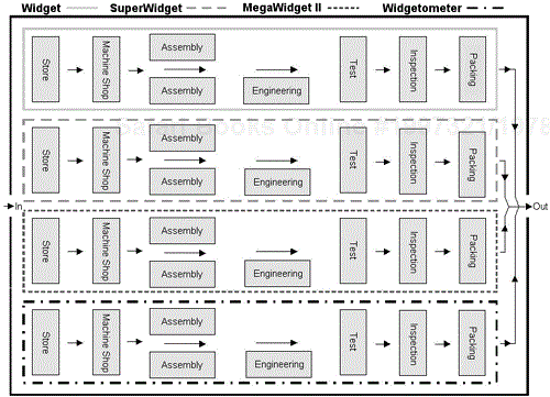
There are four products made at the ACME widget factory, the ubiquitous Widget, its successor the SuperWidget, the top of the line MegaWidget 2000, and the all new method of measuring widgets, the Widgetometer.
Regarding the factory layout (as seen in Figure 3.1), it can be seen that a product's journey through the shop floor is complex, and the distance traveled by the subassemblies and parts is long. Managing a factory such as this one is complicated because any product, part, or subassembly could be anywhere in the factory.
You can think of the factory as a software application, parts going into stores would be input data and shipped products would be output data. The production lines would be top-level components.
Before we improve matters let's define cohesion and coupling and then apply them to the factory layout.
Coupling and cohesion are terms used to describe the effective modularity of a component. They are central to designing robust, maintainable, and reusable software.
Dictionary Definitions
Cohesion—. 1 the act or condition of sticking together; 2 a tendency to cohere; 3 Physics the sticking together of molecules of the same substance
Coupling—. 1 That which connects
Software Academia Definitions
Cohesion—. A measure of how strongly the elements within a module are related. The stronger the better.
The idea of cohesion in software design first appeared in the mid-1960s, courtesy of Larry Constantine. The term was acquired from sociology, where it applies to the relatedness of humans within groups. For our purposes we can think of cohesion as collecting all similar functionality in one component.
Coupling—. A measure of the degree of independence between modules. When there is little interaction between two modules, the modules are described as loosely coupled. When there is a high degree of interaction, the modules are described as tightly coupled.
There are various types of coupling and cohesion defined, but this is outside the scope of this book. In a well-designed component we are looking for loose coupling and strong cohesion.
Now that that's cleared up, back to the factory. Consider that the top-level processes for the factory are deliver a Widget, deliver a SuperWidget, deliver a MegaWidget 2000, and finally deliver a Widgetometer. Each subprocess is dependent on various other subprocesses, and each production line is intertwined with all the others. This is tight coupling. A symptom of tight coupling is the movement of parts and subassemblies around the shop floor, which is closely analogous to the data in software. Each department in the factory is not single-mindedly producing for one production line. It would be very difficult to establish what work is being done where. This is weak cohesion.
It can be seen in Figure 3.2, that by reorganizing the factory into flow lines for each product type and storing parts on the line at the point where they are to be used, the following improvements are made:
Movement of products, parts, subassemblies, and people around the factory has been reduced.
Management of the production lines has been simplified.
The flow line principle turns each production line into a minifactory, independent and unaffected by any other areas of the shop floor. A production line could be removed, modified, or added without affecting any of the others. Production lines therefore exhibit very strong cohesion and are loosely coupled to one another. As described earlier, the factory is analogous to a software application and the production lines are individual components. The internal production line processes could be thought of as private subroutines and the parts as data.
Now consider the following. When you accelerate your car, you are not thinking about how the gasoline is pulled from the tank into the cylinders where it ignites, pushing the piston down, which turns the crankshaft faster, which turns the gears faster, which then turns the driveshaft, which transmits power to the wheels. When you steer, you don't think about the power steering, or for that matter braking and changing gears. Cars are very complex, but as far as the user is concerned this complexity is hidden away behind a simple interface. Not only is it a simple interface but it's a fairly common interface, and luckily automobile manufacturers have agreed on its format and stuck to it. We could otherwise find ourselves in the following situation.
The diagrams in Figure 3.3 illustrate four possible ways of controlling a vehicle; they are four interfaces to the services provided by the vehicle. Transferring from one mode to another would involve learning a new combination of controls. This would not only be tiresome but could be dangerous. The likelihood of an accident is greatly increased during the learning phase.
Dictionary Definition
Encapsulation—. To enclose in a capsule
Software Academia Definitions
Information Hiding—. Information hiding is used to hide complexity behind a simple interface.
Encapsulation—. The process of compartmentalizing the elements of an abstraction that constitute its structure and behavior; encapsulation serves to separate the contractual interface of an abstraction and its implementation.[2]
The information hiding principle was first proposed by D. L. Parnas in 1972 as a criterion for decomposing a software system into modules. The principle states that each module should hide a design decision that is considered likely to change. Each changeable decision is called the secret of the module.
Information hiding allows an implementation to be hidden behind an interface that doesn't change even if the implementation does. The concept of encapsulation is related to information hiding. The data and the operations that manipulate the data are all combined in one place. They are encapsulated within a module.
Information hiding is often touted as a major reason why OO software is more robust. This is true, but with a little effort we can also benefit from implementing information hiding in our system. In a nutshell, all information is hidden away, the only way to get to the data is via its component interface.
So now that we understand the main concepts for software design, how do we implement them in LabVIEW?
Something to keep in mind when looking at the examples and when considering your own designs is that coupling, cohesion, and information hiding are related. By improving information hiding you will generally be improving the coupling and cohesion.
The following examples should help in clarifying the concepts when applied to LabVIEW.
The Front Panel in Figure 3.4 has many different controls and indicators, and their attributes and values will all need changing. The test and logging software behind this front panel was large and complex (1,000+ VIs). The graphing was user-definable and it also had to accommodate all the customers' off-line analyses. The wiring diagram could have ended up like that shown in Figure 3.5.
The term spaghetti code was first used before LabVIEW was developed. One advantage of graphical programming is that it becomes obvious if your program is heading down this route.
In LabVIEW 6i National Instruments tackled this problem by introducing the control reference. This is essentially a means of helping with the real estate issues caused by tightly coupled Front Panel controls and indicators.
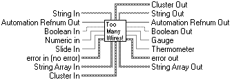
Figure 3.6 demonstrates another good indicator of tight coupling, the amount of wires going in and out of a VI. If a component is strongly cohesive and exhibits good information hiding, it will generally not need more than four or five inputs and a similar amount of outputs.
A question worth asking is, Is the data we're passing essential to the problem domain? There are numerous examples of references and pointers being passed around the software for no better reason than to tie the VIs together.
Going back to the example of the Front Panel as shown in Figure 3.4, another fly in the ointment on this particular project was that the customer wanted the data handling and User Interface done by us off-site (actually we wanted to be off-site). We suggested decoupling the display using message sending through a queue. We implemented a display controller VI that was continuously polled by the Main Display VI. Display updates and attribute changes were sent to the Display Controller and queued in local memory.
This gave us the following benefits:
It allowed us to design, test, and implement the User Interface off-site.
It simplified testing since each state of the display was defined and known.
It allowed a change of Display State to be triggered from almost anywhere within the software.
It allowed changes to be easily and robustly implemented.
A fuller discussion of these User Interface techniques can be found in Chapter 6 on complimentary techniques.
Another example of loose coupling could be a measurement system component. This component conducts all of the measurement functions in a test system. Its interface could be as simple as the example shown in Figure 3.7. Stripped down all you want to do is tell the component what measurement you want and for it to output a number and its status.
The classic example of weak cohesion is if you take a diagram and ring-fence it with your Create SubVI tool, but you do it in a completely haphazard way. If you show no regard at all for the operations that you are ring-fencing, you will have a system that is coincidentally cohesive. From a maintenance point of view a system partitioned like this would be a complete nightmare!
Think about the test system that we discussed earlier. It consists of an oscilloscope and a signal generator. It needs to conduct 30 individual tests. We create 30 VIs (named Test1.vi to Test30.vi). Each one has the GPIB calls to the scope and sig.gen. inside them. A reasonable test of your design is to consider the implications of change. For example a change of test frequency could involve changing specific calls in each one of the test VIs. Missing one call could invalidate the test.
You can improve cohesion simply by collecting like functionality. In this case you could make an Oscilloscope VI, Sig Gen VI, and a Test System VI. The Oscilloscope and Sig Gen VIs encapsulate all the functionality of their respective pieces of equipment. The Test System VI encapsulates all of the states of the test system. Essentially, it would become a wrapper for Oscilloscope and Sig Gen VIs.
The VI shown in Figures 3.8 and 3.9 contains all the functionality required to simply control Word 97's basic functions using ActiveX. Figure 3.10 demonstrates how it is used.
This is an example of strong cohesion because the component only deals with Word 97 and completes all of its functions single-mindedly. If you have any problems with Word 97 you know where to look. If you want to test the component, its functionality is all in one place, and the tests can be easily defined. Adding functionality is purely a matter of adding a command and a new case, none of the existing functionality is changed.
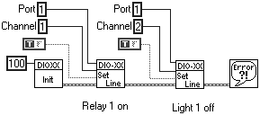
In this example we have a system that uses a Digital Input and Output (DIO) card to control lights and relays. Usually DIO cards work by ports and bytes, so here is one implementation that is used to switch a relay on and a light off (to add to the confusion let's put in a bit of negative logic for the light [true = off, false = on]). The relay will switch power to a unit under test, and the light will tell the user that the unit has power.
We'll be using the NI DIO-XX card that hasn't been newly developed.
Figure 3.11 doesn't look too bad, maybe a little bit of confusion with the negative logic. Now let's multiply it 100-fold. The system is much bigger, there are a lot of switches, actuators, and lights, and the person who wrote the above innocent-looking software has left. They've changed some of the driver hardware and some of the logic of the drivers. You've now got to go wading through the code changing channels and line settings to suit. If your predecessor has been somewhat lax in his or her comments, it could be a bit of a job.
DIO drivers shouldn't be complex, they are only 1s and 0s. If all the software has been written like this, there may be some real complexity in the system.
When thinking about information hiding in components, we need to think about the job that the component is doing and not the way it is going to do it. So revisiting the previous example, let's think about what the component will do.
Switch Power to unit X on.
Switch unit X Power indicator on.
Switch Power to unit X off.
Switch unit X Power indicator off.
The initialize function doesn't have anything to do with the problem domain, the component should decide for itself whether it needs initializing.
Let's redesign the DIO-XX component as shown in Figures 3.12 and 3.13.
Don't worry too much about how this will be implemented for now, all will be revealed later. The implementation is less important than understanding that the component has been redesigned to be more in terms of the system than in terms of the hardware. We are not worried about ports and channels because these are implementation details. What we are interested in is the problem domain (i.e., what actually needs to happen). The redesigned diagram to complete the functions of switching a unit and its indicator on will now look like Figure 3.14.
Dictionary Definition
Abstraction—. A mental concept used to simplify a complex problem
You will come across this term a lot with regard to software design, so it is worth exploring it further.
When you save some text to a file, you will think of it in the terms of sending a string to the “Save to File.vi,” instead of thinking about placing the 1s and 0s onto spare sectors of your hard drive. You are using abstraction to visualize the problem at a manageable level of complexity. The “Save to File.vi” method is at a far more abstract level than the 1s and 0s method.
In software design there are two types of abstraction.
Functional Abstraction: LabVIEW provides the facility to break up your design into subVIs. This hierarchical structure provides functional abstraction. A top-level function can consist of many subfunctions, and these subfunctions can have subfunctions of their own. This is the main way of breaking down the complexities in a problem.
Data Abstraction: Computers deal in 1s and 0s. Programming languages provide a level of abstraction beyond that by giving us more elaborate data types like Integers, Real Numbers, and Strings. LabVIEW also gives you facilities to define your own data types using clusters. Clusters allow you to group related items together, simplifying the moving of data around your application.
By encapsulating and hiding data within our VI we can take abstraction to similar levels as that provided by Object Oriented Programming (OOP). Using message sending as the only way to access and change the data allows us to implement abstract data types. Abstract data types are the basis for good modular design. The following example should help illustrate the advantage of correctly using abstraction in your designs.
We want a component that controls the switching for a measurement system. The underlying technology is a hardware card that turns relays on or off. A low level of abstraction would be the subVIs used to initialize and set or clear the ports on the card. These subVIs could be used as is, and every operation in the measurement system could have the relevant subVI being called to set and clear the required relays. This is shown in Figure 3.15.
A higher level of abstraction is to wrap the relay VI in a component that abstracts the details of relays and channel numbers. We are now talking in terms of the connection made from a system perspective. The Switch VI is used to wrap the relay VIs. All of the relay VIs are now encapsulated in one VI. There should be no way to access the relay VIs from outside the Switch interface. The usage of these new VIs is shown in Figure 3.16.
So how does all this benefit our design? Well, let's compare the hierarchy diagrams in Figure 3.17.
The higher level of abstraction will allow you to make changes to the switching system without actually changing the Switch VI interface. You could swap for a different relay card, for example, or change the switching configuration or the relays called. But the underlying structure of the software will remain the same. The extra layer of abstraction protects the software design from changes. Also, the higher level of abstraction makes your program easier to read. There is no ambiguity about what you want to happen to the switches when you send a command. Ambiguity in software is bad; ambiguity breeds bugs!


