
Chapter 4. Getting Familiar with ACS 5.1
This chapter covers the following subjects:
• Navigating the ACS 5.1 Graphical User Interface
• Adding Network Groups and Devices
• Adding Users to Internal Repositories
ACS 5.1 has a completely different user interface from ACS 4.2. Throughout the course of this chapter you will become familiar with the GUI and know where different functions are located. If this is your first time using ACS 5.1, it is important to take the time to learn how to navigate the interface.
The GUI is broken into two frames. You access different menu items on the left side frame (Navigation Pane) and perform configuration in the right side frame (Content Area). The Monitoring and Reports section is the only exception to this. After you launch the Monitoring and Reports Viewer, a new browser window opens. This new window has a layout similar to the original window but contains menu items related to monitoring and reporting. The left side menu is divided further into drop-down menus or drawers. Click on a drawer to expand it and see a list of options. The available drawers are as follows:
• System Administration
My Workspace
The My Workspace drawer contains:
Welcome Page
The Welcome Page appears when you log in to ACS and provides links to information and shortcuts to some common tasks. Figure 4-1 shows the Welcome Page.
Figure 4-1. Welcome Page
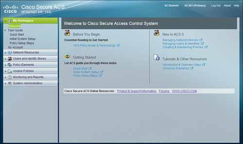
Clicking on the links below the Getting Started section on the Welcome Page creates a new frame in the Content Area. This new frame provides help on how to get started with ACS and contains shortcuts to the initial tasks.
Clicking on any other link in the Welcome Page will open a new window containing the help section. ACS 5.1 has a comprehensive help section and can be accessed using the Help link in the top-right corner of the ACS GUI.
Task Guide
The Task Guide has three menu items:
• Quick Start
• Initial System Setup
• Policy Setup Steps
These items are shortcuts for the links under the Getting Started section on the Welcome Page.
My Account
My Account provides general information regarding the ACS GUI account and assigned roles, and enables you to change the password of your ACS administrator account. No other changes to the account can be made from this section. See Chapter 15, “ACS 5.1 Advanced Configuration,” for information on editing and adding GUI administrator accounts. Figure 4-2 shows the My Account pane.
Figure 4-2. My Account

Network Resources
AAA clients and external RADIUS servers are defined within this drawer. When ACS receives an AAA request from a network device, it searches the network device repository to find an entry with a matching IP address. If a match is not found, the request will be rejected.
This drawer has four menu items:
• Network Devices and AAA Clients
Network Device Groups
AAA clients in the ACS repository can be assigned to Network Device Groups (NDGs). NDGs are logical grouping of devices—for example, by Location or Type—which can be used in policy conditions. For example, all routers in the San Jose location can be assigned a single policy. NDGs simplify creating policies and managing device repository.
NDGs are defined under a hierarchical structure called a Device Group Hierarchy. Each device group hierarchy has a root node under which NDGs are defined. For example, Location and Device Type groups are predefined. The root node of the Location group is All Locations. New NDGs can be created under All Locations. These NDGs can further have other NDGs as child nodes. Figure 4-3 shows a sample hierarchy created under the Locations group. Notice how the NDGs are created countrywise, statewise, or citywise.
Figure 4-3. Hierarchical Structure of NDGs

A maximum of 12 hierarchical groups can be created and each group can have a maximum of six nodes including the root node.
Note
The two hierarchical groups provided—Location and Device Types—cannot be deleted or modified. This leaves 10 groups that can be added.
Clicking on the Network Device Groups menu item will display the existing groups in the Content Area as shown in Figure 4-4. The groups also appear as individual submenu items in the Navigation Pane under Network Device Groups. Click on a group name in the Content Area to edit it. New groups can be created by clicking on the Create button or the Duplicate button.
Figure 4-4. Network Device Groups
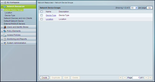
To create a group, follow these steps:
Step 1. Select Network Resources > Network Device Groups.
The Network Device Groups page appears as shown in Figure 4-4.
Step 2. Click Create.
The Hierarchy - General Page appears in the Content Area. Figure 4-5 shows this page.
Figure 4-5. Creating a Network Device Group
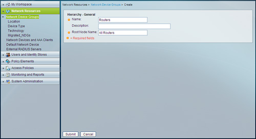
Step 3. Enter a name; for this example, use Routers.
Step 4. (Optional) Enter a description.
Step 5. Enter a root node name. For this example, use All Routers.
Remember that this is any name that refers to all the NDGs and devices in this group.
Step 6. Click Submit to create the group.
The group Routers now appears in the Navigation Pane as a submenu item under the Network Device Group menu item.
Clicking on the group name, Routers, in the Navigation Page will open the Network Device Groups page in the Content Area. Because the group is new, only the root node All Routers will be displayed. This page is similar to the one shown in Figure 4-3. You can add NDGs to the Routers group from this page. To do so, follow these steps:
Step 1. Click Create.
Step 2. Enter a name for the group; for our example, use Core Routers.
Step 3. (Optional) Enter a description.
Step 4. The root node, All Routers, is already selected in the Parent field. If other NDGs existed in the Routers group, you could have clicked on Select to see them and select a different parent node.
Step 5. Click Submit to create the NDG.
Core Routers is now visible under the root node in the Network Device Groups page.
Network Devices and AAA Clients
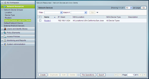
It is important to remember that a device should be in the ACS repository before AAA requests from that device will be accepted. The Network Devices and AAA Clients menu item shows the repository and enables you to manage the devices. Along with the name and address, the page displays the NDG that the device belongs to. You can use the filter option to search for devices. This page is shown is Figure 4-6. To add an AAA client to the ACS database and enable communications using the TACACS+ or RADIUS protocols, you use the following steps:
Step 1. Select Network Resources > Network Devices and AAA Clients.
Step 2. Click Create.
Figure 4-6 shows the Create Network Device page.
Step 3. Enter the hostname of the AAA client, or if this is going to be a group of devices, enter a name that makes it easily recognizable. For this example, use Router1.
Step 4. (Optional) Enter a description.
Step 5. All device groups configured in ACS are shown and their root nodes are selected. Click Select next to the group you want to change to display the Network Device Groups selection box. Click the radio button next to the desired Network Device Group and click OK. For this example, select the San Jose and Core Routers from the Location and Routers groups.
Step 6. A device definition can represent a single or multiple devices. Select Single IP Address or IP Range as required. Selecting IP Range will display options for configuring a mask with the IP address. You can add multiple entries for the range. For this example, use a 192.168.1.0 address with a mask of 24.
Step 7. Select TACACS+ and/or RADIUS and enter the shared secret. You have the option of selecting both protocols for a device. For this example, select TACACS+ and enter Cisco as the shared secret.
Step 8. Click Submit
The device is now listed in the Network Devices and AAA Clients page as shown in Figure 4-7.
Figure 4-6. Adding a New AAA Device

Figure 4-7. Network Devices and AAA Clients
Note
The number of devices that you can add in ACS depends on the license type. The number of devices is determined by the number of unique IP addresses that you configure. This includes the subnet masks that you configure. For example, a subnet mask of 255.255.255.0 implies 256 unique IP addresses and hence the number of devices is 256.
Default Network Device
As mentioned previously, a device needs to be in the ACS repository before AAA requests will be accepted from it. There is an exception to this rule. You can configure a default network device. If a request comes from a device that does not specifically exist in the repository, ACS will use the default device profile. In the default network device definition, you provide a shared secret key, network device group, and the protocol(s) to be used. To configure the default network device, follow these steps:
Step 1. Select Network Resources > Default Network Device.
The Default Network Device page appears. Figure 4-8 shows this page.
Figure 4-8. Default Network Device

Step 2. Select Enabled from the drop-down list next to Default Network Device Status.
Step 3. Click Select next to the device groups that you want to modify. For our example, select San Jose NDG from the Locations Group.
Step 4. Select TACACS+ or RADIUS and enter the shared secret for the protocols. You can select one or both the protocols. For this example, select both the protocols and use Cisco as the shared secret.
Step 5. Click Submit.
External RADIUS Servers
ACS 5.1 can function both as a RADIUS server and a RADIUS proxy server. When it acts as a proxy server, ACS receives authentication and accounting requests from the AAA client and forwards them to the external RADIUS server. ACS accepts the results of the requests and returns them to the client. You must configure the external RADIUS servers in ACS to enable ACS to forward requests to them. You can configure multiple external RADIUS servers. To add a server, follow these steps:
Step 1. Select Network Resources > External RADIUS Servers.
The External RADIUS Servers page appears with a list of configured servers.
Step 2. Click Create.
The Create Server page appears as shown in Figure 4-9.
Figure 4-9. Adding an External RADIUS Server

Step 3. Enter a name for the server. For this example, use External1.
Step 4. (Optional) Enter a description.
Step 5. Enter the server IP address. For this example, use 192.168.1.40.
Step 6. Enter the shared secret. This secret is used to encrypt the RADIUS request between ACS and the external server. For this example, use Cisco.
Step 7. Click Advanced Options.
Step 8. Verify the authentication and accounting ports.
By default, ports 1812 and 1813 are used. If the external server uses other ports, enter them in the respective fields. This example leaves the ports set to the default values.
Step 9. Verify the server timeout value.
By default, five seconds timeout period is used. If the server fails to respond in that period, the server will resend the request as many times as specified in the Connection Attempts field. You can specify a timeout value of 1 to 120 seconds. For this example, specify 10 seconds.
Step 10. Verify the connection attempts value.
By default, ACS will attempt to connect to the external server three times. You can configure ACS to attempt up to 10 times to connect to the external server. For this example, specify five attempts.
Step 11. Click Submit.
Users and Identity Stores
To authenticate and authorize a user or host, ACS uses the user definitions stored in identity stores. There are two types of identity stores:
• Internal Identity Stores: Identity stores that ACS maintains locally are called internal identity stores. ACS maintains two different internal identity stores for user and host records. These stores are accessible from the Internal Identity Stores menu item in the Users and Identity Stores drawer.
• External Identity Stores: Identity stores that reside outside of ACS are called external identity stores (or external user databases in earlier versions of ACS). Each external identity store requires certain configuration before ACS can obtain information from it. The External Identity Stores menu item under the Users and Identity Stores drawer can be used to configure these stores.
In this chapter, you add a user and a host to the internal identity stores. External identity stores are discussed in Chapter 5, “Configuring External Databases with ACS.”
Before adding a user or host, you should know about identity groups and how to add them.
Identity Groups
Identity groups, as the name suggests, are groups of users or hosts. As in ACS 4.2, users and hosts can be put in a group to apply a uniform policy on them.
Note
A key point to remember is that ACS 4.2 is a group-based server, whereas ACS 5.1 is a policy-based server. This means that users and groups in ACS 5.1 do not have reply attributes configured in their profile. Reply attributes are derived from policy evaluation.
Identity groups are defined in a hierarchical structure like the NDGs. All Groups is the root of this hierarchy.
To create an identity group, follow these steps:
Step 1. Select Users and Identity Stores > Identity Groups.
The Identity Groups page appears.
Step 2. Click Create.
The Create Identity Group page appears as shown in Figure 4-10.
Figure 4-10. Creating an Identity Group

Step 3. Enter a unique name for the group. For our example, use Admin.
Step 4. (Optional) Enter a description.
Step 5. Click Select to select a parent group for this group. For this example, use the Root group.
Step 6. Click Submit.
The Identity Group page appears with the Admin group listed under the root.
Adding a User in the Internal Identity Store
Adding a user to the internal identity store is very simple in ACS 5.1. To add a user, follow these steps:
Step 1. Select Users and Identity Stores > Internal Identity Stores > Users.
The Internal Users page appears.
Step 2. Click Create.
The User Properties page appears as shown in Figure 4-11.
Figure 4-11. Adding a User to the Internal Identity Store

Step 3. Enter a name for the user. This name will be used by the user to authenticate. For our example, use User1.
Step 4. (Optional) Enter a description.
Step 5. Click Select and select an identity group for the user. For this example, select the Admin group created in the previous section.
Step 6. Enter the password and confirm the password. The password must match the restriction shown in the Password Information section on the page. By default, the password must be 4 to 32 characters long. For this example, use Cisco as the password.
Step 7. (Optional) An enable password can be entered for users to log in to the privilege mode of devices. This option is enabled by default and can be disabled from the User Authentication settings section. For this example, leave this field blank.
Note
Identity attributes can be used in a policy. For more information on dictionaries and identity attributes see Chapter 15, “ACS 5.1 Advanced Configuration.”
Step 8. Click Submit.
The user configuration will be saved and the Internal Users page will appear with the new user listed.
Adding a Host in the Internal Identity Store
Adding a host in the ACS internal data or identity store is not a new concept. In versions of ACS prior to ACS 5.1, the MAC address of a host could be added as a user for MAC address-based authentication. ACS 5.1 provides separate user and host identity stores! Steps for adding a host in the internal identity stores are similar to that of adding a user. To add a host, follow these steps:
Step 1. Select Users and Identity Stores > Internal Identity Stores > Hosts.
The Internal Hosts page appears.
Step 2. Click Create.
The host properties page appears as shown in Figure 4-12.
Figure 4-12. Adding a Host to the Internal Identity Store

Step 3. Enter the MAC address of the host. You can enter the MAC address in any of the following formats:
—xx-xx-xx-xx-xx-xx
—xx:xx:xx:xx:xx:xx
—xxxx.xxxx.xxxx
—xxxxxxxxxxxx
Although you can enter the MAC address in any of the formats in the preceding list, ACS will convert and store the MAC address in the first format. For this example, use 00-19-01-02-AA-EE.
Step 4. (Optional) Enter a description.
Step 5. Click Select and select an identity group. For our example, use the Admin group created in the previous sections.
Step 6. Click Submit.
The host configuration will be saved and the Internal Hosts page will appear with the new host listed.
Note
The Users and Identity Stores drawer contains Certificate Authority and Certificate Authentication Profiles menu items. These are used to configure ACS for Certificate based authentication. These sections are discussed in Chapter 8, “IOS Switches.”
The Identity Store Sequences menu item is used to define sequences of databases to be used in a policy. This section is covered in Chapter 5, “Configuring External Databases with ACS.”
Policy Elements
You know from Chapter 2 that ACS 5.x is based on a rule-based policy model. You also know that the rules are called policies and they consist of conditions and results, which are called policy elements. In this section and the next, you will learn more about policy elements and how to create them, the different types of policies, and the flow of a request through different processes in ACS.
Before creating policies, you must create policy elements, which are the building blocks of policies. Policy elements are divided into two types: session conditions and authorization and permissions.
Session conditions are conditions used to apply policies to requests. Some conditions are available by default, whereas others can be created by you. The following conditions are available by default:
• Request/Protocol Attributes: These attributes are derived from the authentication request itself.
• Identity Attributes: Identity attributes are derived from the user definition in the internal identity store or external repositories such as LDAP and Active Directory. The attributes need to be mapped in the external database configuration before they become available in the policies. See Chapter 5 for more on external databases and attribute mapping.
• Identity Groups: You can map every user and host to an identity group. This group association can be used in policies as a condition.
• Network Device Groups(NDGs): Each device is associated with an NDG. This association can be used as a condition in the policies.
The following conditions can be created by you:
• Date and Time Conditions: You can create conditions that define specific time intervals across days of the week. These conditions take into account the current date and time and return a true or false result indicating whether the condition is met.
• Custom Conditions: You can create conditions based on attributes of various identity and protocol dictionaries which are available in ACS. These conditions allow you to apply policies based on the authentication and authorization requests received from AAA clients.
• Network Conditions: You can create conditions based on the following to restrict access:
• End Station Filters: These are based on end stations that initiate and terminate the connection. End stations may be identified by IP Address, MAC Address, or Caller Line Identification (CLI) and Dialed Number Identification Service (DNIS) fields obtained from the request.
• Network Device Filters: Based on the AAA client that processes the request. A network device can be identified by IP address, the name of the device that is defined in the network device repository or the network device group (NDG).
• Device Port Filters: Network device definition might be supplemented by the device port that the end station is connected to.
These filters or conditions can be included in policy conditions. This set of definitions is matched against those presented in the request. The operator that you use in the condition can either be match (in which case the value presented must match at least one entry within the network condition) or no matches (in which case it should not match any entry in the set of objects present in the filter).
Authorization and permissions are the results applied to a request that matches a condition in a policy. You can define the following types of results:
• Authorization Profiles: You can define a set of attributes and values that is returned to the device in Access-Accept responses for network access requests. These profiles can contain common data such as VLAN information, reauthentication timer, or any RADIUS attribute.
• Shell Profiles: You can define a set of permissions that is applied to a user requesting administrative access of a device. Some of these permissions include privilege level, auto command, and custom TACACS+ attributes.
• Command Sets: You can define a list of commands that a user can execute on a device during an administrative session.
• Downloadable ACLs: You can define downloadable ACLs that can be sent to a device with an Access-Accept message.
If you have worked on previous ACS versions (4.x or 3.x), you must have noticed that many of the policy elements were available earlier in the Group Setup. The difference in ACS 5.x is that these conditions and results are now defined globally and can be used in multiple rules. Group-based configuration required configuring the conditions and results in each group even if they were similar.
Figure 4-13 shows a typical simplified flow of a request through ACS. Note the different places where policy elements are used. At this stage, do not worry about the different policies shown in the figure because they will be covered later in the chapter.
Figure 4-13. Flow of a Request Through ACS 5.x
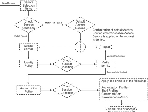
The following sections look at creating the different policy elements.
Session Conditions: Date and Time
To create a Date and Time session condition, follow these steps:
Step 1. Select Policy Elements > Session Conditions > Date and Time.
Step 2. Click Create.
The Date and Time Properties page appears as shown in Figure 4-14.
Figure 4-14. Creating Date and Time Condition
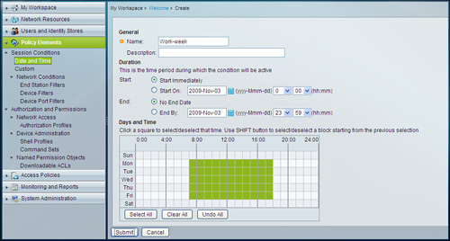
Step 3. Enter a name. For this example, use Work-week.
Step 4. (optional) Enter a description.
Step 5. Define start and end times for this element. During the period defined, the element can be used by policies. You can select Start Immediately and No End Date for the element to be active always or select a specific date and time during which this element will be active. This is useful when you want to provide some access or privilege for only a certain duration. For our example, select the Start Immediately and No End Date options.
Step 6. Select the days and time during which this element will return a positive reply for access request. Each square in the grid is equal to one hour. Select a grid square to make the corresponding time active. For this example, select 7:00 to 18:00 hours, Monday to Friday as shown in Figure 4-14.
Step 7. Click Submit.
The policy element you created will restrict access to 7:00–18:00 hours on Monday through Friday, when applied to a policy.
Session Conditions: Custom
To create a custom session condition, follow these steps:
Step 1. Select Policy Elements > Session Conditions > Custom.
Step 2. Click Create.
The Custom Condition Properties page appears. This page is shown in Figure 4-15.
Figure 4-15. Creating a Custom Session Condition

Step 3. Enter a name. For our example, use Protocol.
Step 4. (optional) Enter a description.
Step 5. Select Dictionary from the drop-down list. Different Protocol and Identity dictionaries are available in the drop-down list. For our example, select RADIUS-IETF.
Step 6. Click Select next to the Attribute text box and select an attribute. For our example, select Framed-Protocol.
Step 7. Click Submit.
The custom condition that you just created will match the Framed-Protocol attribute in a RADIUS request when applied to a policy.
Session Conditions: End Station Filters
To create an end station filter, follow these steps:
Step 1. Select Policy Elements > Session Conditions > Network Conditions > End Station Filters.
Step 2. Click Create.
The End Station Filter Properties page appears as shown in Figure 4-16.
Figure 4-16. Creating an End Station Filter

Step 3. Enter a Name. For this example, use Host List 1.
Step 4. (optional) Enter a description.
Step 5. End stations can be filtered by IP address, MAC address, or Calling Line ID (CLI)/Dialed Number Identification Service (DNIS). The filter values are added under the respective tabs. For this example, select the IP Address tab.
Step 5. Click Create.
A dialog box opens where you can enter an IP address or a range of addresses. For this example, select IP Range(s) and enter 192.168.1.0 in the IP text box and 24 in the Mask text box. Click Ok.
192.168.1.0/24 is now listed in the Network Devices table.
Note that the options in the dialog box will change depending on the tab selected.
The filter you created will match any host in the 192.168.1.0/24 when applied to a policy.
Session Conditions: Device Filters
To create a device filter, follow these steps:
Step 1. Select Policy Elements > Session Conditions > Network Conditions > Device Filters.
Step 2. Click Create.
The Device Filter Properties page appears as shown in Figure 4-17.
Figure 4-17. Creating Device Filters

Step 3. Enter a name. For this example, use Core Routers.
Step 4. You can enter the IP addresses of devices, the names of devices already in the ACS repository, or a network device group under the respective tabs. For this example, select the Network Device Group tab.
Step 5. Click Create.
A dialog box appears where the NDG can be selected. Click Select next to the NDG Type text box and select the Routers group that you created earlier. Then click on Select next to the NDG Value text box and select the Core Routers group that you created earlier. Click Ok.
The Core Routers NDG is now listed in the Network Devices table.
Note that the options in the dialog box will change depending on the tab selected.
The device filter you created will match any device in the Core Routers NDG when applied to a policy.
Session Conditions: Device Port Filters
The steps to create a device port filter are similar to the one you followed to create device filters. The only difference is the addition of a Port text box in the dialog box where you select or enter device information. Figure 4-18 shows the Device Port Filter properties page where the Core Routers NDG is added with port 23.
Figure 4-18. Creating Device Port Filters

Note
Authorization and permissions policy elements are covered in later chapters.
• Authorization profiles are covered in Chapter 8, “IOS Switches.”
• Shell profiles and command sets are covered in Chapter 6, “Administrative AAA on IOS.”
Downloadable ACLs are covered in Chapter 10, “Cut-Through Proxy AAA on PIX/ASA.”
Access Policies
Before you start creating policies, it is important to understand how ACS applies a particular policy to a request and how many policies are available. ACS uses service selection rules and access services to decide on a policy to apply to a request.
Service Selection Rules
Service selection rules decide which access service to send an authentication or authorization request to. You can configure ACS to use a single access service to process all requests or use rules based on session conditions to send requests to different access services. In the case of a rule-based selection, ACS uses the first rule from the top that matches a request.
Note
When rules are used for service selection, ACS provides an option to configure a default rule. If a request does not match any rules in the table, the default rule is applied.
To further understand how this works, take a department store for example. A department store is divided into sections using product category (clothing, sporting goods, jewelry, and so on). An ACS configured to use a single access service is like the department store. All requests go to a single access service, which has different policies. The access service checks session conditions and applies the appropriate policy. Consider a grocery store for another example. A grocery store sells only groceries, but might have sections based on different categories (produce, meat, canned goods, and so on). An ACS configured for rule based service selection is similar to such a store. It will send different kinds of requests to different access services. Each access service equates to a specialized store. These access services will have different policies.
To further understand service selection rules and access services, consider another example. XYZ Inc. has five offices. Each office has routers terminating VPN connections. These routers are going to authenticate and authorize VPN sessions and administrative sessions to a single ACS. There are two ways to configure ACS for the organization:
• Method 1: Configure ACS to send all requests to a single access service and configure two policies in the access service. One policy to process all administrative session requests via the TACACS+ protocol and the other to process all VPN session requests via the RADIUS protocol.
• Method 2: Configure ACS to send all TACACS+ (administrative sessions) requests to one access service and to send all RADIUS (VPN sessions) request to another access service. Each access service can have one or more policies to process the requests.
Method 1 is easier to configure and maintain; however, it can get very complicated if different authentication or authorization methods need to be applied. For example, one site might need more stringent authorization for VPN sessions than other sites or administrators might need restricted access to remote devices. Further consider an organization with 100 sites and thousands of network devices. In such scenarios, policies will increase in the access service and soon become unmanageable. On the other hand, different access services will have a smaller number of policies and will be easier to manage.
Access Services
Access services are the most basic parts of ACS. They are sets of policies which process all authentication and authorization requests. Every authentication and authorization request has to match a policy in an access service before it is processed. As you already know, a request is sent to an access service by the service selection rules. When an access service receives a request, it checks policies in a top-down manner and applies the first policy that matches the session conditions.
Access services consist of the following types of policies:
• Identity Policy: Specifies how the user should be authenticated and includes the allowed authentication protocols and the user repository to use for password validation. Identity policies can be simple or rule based. Simple policies apply a single policy to all requests. Rule-based policies use session conditions to choose rules for requests.
• Group Mapping Policy: Specifies whether the user’s ACS identity group should be dynamically established based on user attributes or group membership in external identity stores. The user’s identity group can be used as part of its authorization. Chapter 5 covers group mapping in more detail.
• Authorization Policy: Specifies the authorization rules for the user. Authorization policies can only be rule based.
Note
If a policy is rule based, ACS checks rules in a top-down manner and uses the first rule that matches. ACS also provides an option to configure a default rule. If a request does not match any rules in the table, the default rule is applied.
ACS has two access services by default:
• Default Device Admin: Service selection rules are configured to send all TACACS+ requests to this default access service.
• Default Network Access: Service selection rules are configured to send all RADIUS requests to this default access service.
Creating an Access Service
Access services and their policies bring together different elements from ACS. Hence, before creating an access service, you should determine the network configuration and the degree of refinement that you want individual policies to have. Depending on that, you should add devices and users or user databases. You should also create different policy elements such as session conditions and authorization and permission elements. Ensuring that you have all the required components will save you from moving back and forth between different drawers in the menu.
To create an access service, follow these steps:
Step 1. Select Access Policies > Access Services.
The Access Services page appears.
Step 2. Click Create.
The Access Service General Properties page appears as shown in Figure 4-19.
Figure 4-19. General Properties of a New Access Service

Step 3. Enter a name. For this example, use Remote Access VPN.
Step 4. (optional) Enter a description.
Step 5. Select one of the following options for Access Service Policy Structure:
• Based on service template: Creates an access service based on a predefined template. These templates are customized to use a specific condition type. To use this option, select the radio button next to it, and then click Select and select a template.
• Based on existing service: Creates an access service containing policies based on an existing access service. The new access service does not include the existing service’s policy rules. To use this option, select the radio button next to it, and click Select and select an existing access service.
• User Selected Service Type: Provides you the option to select the access service type. The available options are Network Access, Device Administration, and RADIUS Proxy. The list of policies you can configure depends on your choice of access service type. To use this option, select the radio button next to it and select an access service type from the drop down box. Selecting this option will also display the option to enable or disable different policy types.
For this example, select User Selected Service Type and select Network Access from the drop-down box. Select Identity and Authorization in the policy structure.
Step 6. Click Next.
The Allowed Protocols properties page appears as shown in Figure 4-20.
Figure 4-20. Configuring Allowed Protocols in an Access Service

Step 7. This page enables you to select which authentication protocols will be allowed with this access service. PAP, CHAP, MS-CHAPv1, MS-CHAPv2 and various EAP protocols are available as options. You can also enable host lookup (required for machine authentication) from this page. For this example, deselect Process Host Lookup and select Allow PAP/ASCII and Allow MS-CHAPv2.
Step 8. Click Finish.
The access service will be saved and will appear as a menu item in the Access Services drawer. Below the menu item, selected policy types will be shown as submenu items. At this point, a prompt will give you an option to activate this service in the Service Selection Rules. For now, click No. The Access Services page will appear with the new access service listed in the table.
You are now ready to configure the identity rules and authorization rules for the new access service.
Configuring Identity Policy
As you already know, identity policies can be simple or rule-based. By default, identity policies are simple. When you select Identity under a new Access Service (Remote Access VPN for this example) in the Access Policies drawer, you will find that the Single result selection option is selected and Identity Source is DenyAccess.
If you want to configure a simple policy, follow these steps:
Step 1. Click Select next to Identity Source and select an identity store. You can select between certificate-based authentications or different password-based internal or external identity stores.
Step 2. (Optional) Click Advanced Options to display the fail-open options. Fail-open opens enable you to configure the behavior of ACS when authentication fails, the user is not found in an identity store, or there is a process failure. A process failure occurs when ACS is not able to verify the credentials, usually due to external factors such as a network failure between ACS and an external database. To understand the fail-open process, you have to remember that a device will fail over to a different AAA server if the primary server does not respond to a request. Each of the three fail-open options has three possible actions:
• Reject: Sends an Access-Reject or Fail reply to the AAA client.
• Drop: ACS drops the request, causing the AAA client to retry another fail over to another AAA server.
• Continue: Causes ACS to try the next service or rule.
By default ACS will reject a request if authentication fails or a user is not found, and will drop a request if the process fails. Figure 4-21 shows this page with the default Advanced options.
Figure 4-21. Configuring a Simple Identity Policy

Step 3. Click Save Changes.
If you want to configure a rule-based identity policy, follow these steps:
Step 1. Select Rule based result selection from the Identity Properties page.
This will change the properties page to a rule-based table format shown in Figure 4-22.
Figure 4-22. The Identity Policy Page for a Rule-Based Configuration

Step 2. The rules of an Identity policy use session conditions to determine which identity store to use for a request. The session conditions available in the Rules Properties page need to be enabled from the Identity Properties page. Click Customize to open the Customize Conditions dialog box. Select the conditions that you want to use. For this example, deselect default conditions and select NDG:Routers (you created this NDG earlier in this chapter).
Step 3. Click Create.
The Identity Rule properties page appears as shown in Figure 4-23.
Figure 4-23. Configuring the Rules of an Identity Policy

Step 4. Enter a name. For this example, use Core Routers.
Step 5. Select a session condition. In this example, only NDG:Routers is available, so select it.
Step 6. Select an operator from the drop-down box next to the selected condition. The available operators change depending on the condition selected. These are logical operators that allow matching or not matching the user-provided argument with the selected condition. For this example, select in from the drop-down box.
Step 7. For some conditions, such as NDGs, you will see a Select button next to the condition. You can click this button to select the required element. For some conditions, you will get a drop-down box or a text box. For this example, click Select and select Core Routers NDG.
Step 8. In the Results section, you can select the identity source to be used for this rule. Click Select next to Identity Source and select an identity store. You can select between certificate-based authentications or different password-based internal or external identity stores. For this example, use Internal Users.
Step 9. (Optional) Click Advanced Options to display the fail-open options. Remember that by default, ACS will reject a request if authentication fails or a user is not found, and will drop a request if the process fails. For this example, leave them set to the default values.
Step 10. Click OK.
The rule will be saved and the Identity Policy page will appear with the rule listed in the table.
The rule you created will use the Internal Users identity store to authenticate requests that originate from any device in the Core Routers NDG. You can add more rules to use different identity stores for different session conditions.
Now that the identity policy is configured, you can configure the authorization policy to complete the access service.
Configuring Authorization Policy
As mentioned earlier, authorization policies are rule based only. You cannot configure a simple authorization policy, but you can configure a single rule that will match all requests coming to the access service.
ACS also provides a default authorization rule. The default rule is applied if no rules are defined in an authorization policy or if a request does not match any defined rules.
Note
I strongly suggest that you do not use the default rule to avoid security lapses. Using the default rule in most circumstances is like having a gate but leaving it open. You should have explicit rules for all variations of requests you get.
To configure a rule, follow these steps:
Step 1. Select Access Policies > Access Service you want to change > Authorization. For this example, select Authorization under Remote Access VPN.
The Authorization Policy page appears.
Step 2. Rules of an authorization policy use session conditions to determine which authorization and permissions to use for a request. The session conditions available in the Rules Properties page need to be enabled from the Authorization Policy page. Click Customize to open the Customize Conditions dialog box. Select the conditions that you want to use. For this example, deselect default conditions and select Identity Group.
Step 3. If the authorization policy for a TACACS+-based access service is being configured, then along with available session conditions, you will need to select available results in the Customize dialog box. Results can be shell profiles or command sets. For this example, you will not have an option to select results because the access service is RADIUS-based. Authorization Profile is the only result available with such access services.
Step 4. Click Create.
The Authorization Rule properties page appears as shown in Figure 4-24.
Figure 4-24. Creating the Rules of an Authorization Policy

Step 5. Enter a name. For this example, use Admins.
Step 6. Select a session condition. For this example, select Identity Group.
Step 7. Select an operator from the drop-down box next to the selected condition. The available operators change depending on the condition selected. These are logical operators that allow matching or not matching a user-provided argument with the selected condition. For our example, select in from the drop-down box.
Step 8. For some conditions, such as Identity Group, you will see a Select button next to the condition. You can click this button to select the required element. For some conditions your will get a drop-down box or a text box. For this example, click Select and select the Admin group you created earlier.
Step 9. Authorization profiles require you to select a result. Results can be authorization profiles, shell profiles, or command sets depending on the access service. Click Select next to the result that you want to configure and select a policy element. For this example, select the Permit Access authorization profile, which is available by default.
Step 10. Click OK.
The rule will be saved and the Authorization Policy page will appear with the new rule listed in the table.
You have created your first authorization rule, which permits access if the user belongs to the Admin Identity group.
Now that the access service configuration is complete, you will need to create a service selection rule so that this service is used.
Creating Service Selection Rules
As you know, service selection rules decide which access service to apply to a request. By default ACS is configured for rule-based service selection. Two rules are present by default. The first rule, named Rule-1, sends all RADIUS requests to the Default Network Access service and the second rule, named Rule-2, sends all TACACS+ requests to the Default Device Admin service. To configure ACS to use the Remote Access VPN service that you created, you need to add a new rule for service selection. You have the following choices in this situation:
• Edit Rule-1 to send all requests to the Remote Access VPN service
• Delete Rule-1 and create a new rule
• Create a new rule above Rule-1 that is specific to the Remote Access VPN service
For this example, create a new rule above Rule-1. To do so, follow these steps:
Step 1. Select Access Policies > Access Services > Service Selection Rules.
The Service Selection Policy page appears.
Step 2. The session conditions available in a service selection rule properties page can be customized from this page. Click Customize and select the required conditions. For this example, select NDG:Location and Protocol.
Step 3. Select Rule-1 and click the down arrow on the Create button.
Step 4. Select Create Above.
The Service Selection Rules properties page appears as shown in Figure 4-25.
Figure 4-25. Creating a Service Selection Rule

Step 5. Enter a name. For this example, use San Jose VPN.
Step 6. Select the conditions that define the rule. For this example, select Protocol and NDG:Location.
Step 7. Select an operator from the drop-down box next to the selected condition. The available operators change depending on the condition selected. These are logical operators that allow matching or not matching a user-provided argument with the selected condition. For this example, select match for Protocol and in for NDG:Location.
Step 8. For some conditions, such as NDG:Location, you will see a Select button next to the condition. You can click this button to select the required element. For some conditions, you will get a drop-down box or a text box. For this example, click Select and select San Jose for NDG:Location and RADIUS for Protocol. If you have not created the San Jose group, select the All Locations option for NDG:Location.
Step 9. The result of a service selection rule is an access service or DenyAccess. You can use the drop-down box to select the result for the rule. For this example, select Remote Access VPN from the drop-down box.
Step 10. Click Ok.
The rule will be saved and the Service Selection Policy page will appear with the new rule listed above Rule-1 in the table.
The rule you created will send RADIUS requests originating from devices in the San Jose NDG or All Locations NDG to the Remote Access VPN access service which you created earlier. The access service and policies that you created in the previous sections will authenticate RADIUS requests originating from a device in the Core Routers NDG using the Internal User identity store. If authentication is successful and the user belongs to the Admin identity group, the access will be permitted. Further chapters will help you create more complex access services and policies. The examples in this chapter are used to explain the basic process of creating policies and rules.
Monitoring and Reports
The Monitoring and Reports drawer replaces the Reports and Activity section of previous versions of ACS. You can now view reports based on different criteria such as Access Service, End Point, and Failure Reason, among others. ACS 5.x also introduces a configurable dashboard for reports and alarms.
Note
ACS 5.x has added monitoring, reporting, and troubleshooting capabilities that are similar to those available is ACSView 4.0. ACSView is an independent reporting and monitoring platform available for ACS 4.x.
Covering the entire Monitoring and Reports section in depth is beyond the scope of this book. This section of the text will focus on the reports that are most important and touch on the rest briefly.
The Monitoring and Reports drawer contains the Launch Monitoring and Report Viewer option. Click this option to open the Monitoring and Reports Viewer in another browser window or tab. The layout of the new window is similar to the main window but contains only the following two drawers:
• Monitoring and Reports
• Monitoring Configuration
The Monitoring and Reports drawer contains the following options:
• DashBoard: ACS 5.1 provides a new customizable dashboard that contains tabs and portlets where your favorite queries, recent alarms and reports, and health status of ACS reside. Each of these tabs can have multiple portlets, with each portlet containing an application of your choice. You can select an application from the available list. Some of the important applications available in the dashboard by default are as follows:
• Recent Five Alarms: This application is available in the General tab and shows the latest five alarms.
• Favorite Reports: This application contains links to favorite reports. The favorite list is configuration from the Reports option discussed later.
• Live Authentications: This application is available in the Troubleshooting tab and shows authentication requests received in real time. This is a very useful application for troubleshooting. By default, it refreshes every 10 seconds and is configured to monitor RADIUS requests.
• NAD Show Command: A neat little application that can connect to a network device using SSH or Telnet and run a show command. You have to provide the login details and the show command to run. ACS will display the output in a new window. This is also a very useful application. It saves you from jumping between ACS GUI and Telnet or SSH clients.
• ACS Health Status: Shows the health of the ACS server.
• Alarms: ACS 5.x introduces alarms. The monitoring component retrieves data from ACS and generates alarms to notify you of critical system conditions. These alarms can be viewed in the Inbox option in this drawer or can be received through Syslog and email. There are two types of alarms in ACS: Threshold and System. Threshold alarms are defined on logs collected from ACS. You can configure a threshold alarm to notify you of different events such as authentication activity, system health, and process status, among others. System alarms notify you of critical conditions encountered during the execution of the ACS Monitoring and Reporting viewer. System alarms also provide the informational status of system activities, such as data purge events or the failure of the log collector to populate the View database. You cannot configure system alarms. This drawer contains the following options:
• Inbox: Generated alarms can be viewed in the Inbox. After you view an alarm, you can edit the status of the alarm, assign the alarm to an administrator, and add notes to track the event.
• Thresholds: You can configure thresholds from this page. A maximum of 100 thresholds can be configured in an ACS server. Four thresholds exist by default, out of which only the System Errors threshold is enabled.
• Schedules: Each threshold has a schedule associated with it. The schedule defines when a threshold is run. You need to configure schedules on this page before you can use them in thresholds. By default, ACS has a nonstop schedule that monitors events 24 hours a day, seven days a week.
• Reports: The Reports section contains different predefined reports that you can use to monitor and troubleshoot ACS. These reports include authentication and authorization reports (similar to passed and failed reports from ACS 4.x), access service reports, ACS configuration and operation audits, and network device summary, among others. You can add any of the reports to your Favorites and those will be displayed in the General tab of the dashboard. The following report categories are available in the catalog:
• AAA Protocol: Contains RADIUS and TACACS+ authentication, authorization (TACACS+ only) and accounting reports, AAA diagnostics, and authentication trend. Passed and failed logs from previous ACS version have been divided into protocol-specific authentication and authorization reports. Figure 4-26 shows the TACACS+ authentication report.
Figure 4-26. TACACS+ Authentication Report

• Access Service: Contains a graphical summary report and a top count report for authentication in respect to access services.
• ACS Instance: Contains different system-related reports such as configuration and operations audit reports, health summary, administrator logins and entitlement reports, and ACS system diagnostics.
• Endpoint: Contains MAC address-based authentication summary reports, MAC address-based top authentications reports, and machine-based top authentication reports.
• Failure Reason: Contains summary and top authentication failure reports. This is one of the most important reporting sections. A close look at this section can tell you about any access attacks being carried out against your network.
• Network Device: Contains summary and top authentication reports in respect to network devices. These reports are useful in tracking which devices are generating the maximum number of requests.
• Session Directory: Contains active session, terminated sessions, and session history reports for RADIUS and TACACS+. Accounting packets received from devices are used to maintain session information.
• User: Contains summary and top authentication reports in respect to users.
• Troubleshooting: ACS 5.x contains some nice troubleshooting options. The following options are available in the Troubleshooting section:
• Connectivity Tests: You can run a ping, traceroute, and nslookup for a hostname or IP address to see whether the device is reachable from ACS. This is important to see whether the requests from a device and replies from ACS to the device are not getting dropped in the network.
• ACS Support Bundle: The support bundle is a zip archive of diagnostic information, including system log files. You can also choose to include ACS configuration, ACS debug log files, ACS localstore log files, and core files. This support bundle will be needed by the Cisco Technical Assistance Center (TAC) for troubleshooting.
• Expert Troubleshooter: This section contains some nice tools to check the configuration of a device and ACS. Using RADIUS Authentication troubleshooting tool, you can select a failed or passed log from RADIUS authentication report and have it check the ACS and device configuration to see why the authentication failed or passed. Figure 4-27 shows the report generated by this tool when changing the RADIUS shared key on the device. This section also contains the NAD show command application from the dashboard and the Evaluate Configuration Validator, which checks the configuration of a device to see whether it is configured properly for a task such as IEEE 802.1X authentication.
Figure 4-27. RADIUS Authentication Troubleshooting Tool at Work

The Monitoring Configuration drawer contains various configuration options for the Monitoring and Report Viewer. Configuration of ACS View (the Monitoring and Reporting part of ACS 5.x) is out of the scope of this book.
Note
The System Administration drawer contains various advanced configuration options for ACS. These options are covered in Chapter 15.
ACS 5.1 Command-Line Interface (CLI)
ACS 5.x, unlike previous versions, provides a CLI for configuration and monitoring along with a GUI. You can access the ACS CLI through a secure shell (SSH) client or the console port.
Two different types of accounts are available for accessing the CLI:
• Admin: Admin accounts have full configuration and monitoring access.
• Operator: Operator accounts have monitoring access only.
This section assumes use of an Admin account to access the CLI.
The ACS CLI is similar to IOS CLI in look, feel, modes, and command structure. You can use the question mark (?) to see the help and the Tab key to complete a command. Logging in to the ACS server places you in the Operator (user) mode or the Admin (EXEC) mode. Typically, logging in requires a username and password.
You can always tell when you are in the Operator (user) mode or Admin (EXEC) mode by looking at the prompt. A right angle bracket (>) appears at the end of the Operator (user) mode prompt; a pound sign (#) appears at the end of the Admin mode prompt, regardless of the submode.
Three command modes are available on the CLI:
• EXEC: EXEC commands primarily include system-level commands such as show and reload (for example, application installation, application start and stop, copy files and installations, restore backups, and display information). In addition, certain EXEC-mode commands have ACS-specific abilities (for example, start an ACS instance, display and export ACS logs, and reset an ACS configuration to factory default settings).
• ACS Configuration: Commands in this mode can be used to set the debug log level for the ACS management and runtime components, show system settings, reset server certificates and IP address access lists, and manage import and export processes. To access the ACS configuration mode, run the acs-config command in EXEC mode as demonstrated in Example 4-1.
Example 4-1. ACS CLI—Changing to ACS Configuration Mode

• Configuration: Commands in this mode can be used to configure various system options such as interface, repository, SNMP server, and NTP, among others. To access the Configuration mode, run the configure command in EXEC mode as demonstrated in Example 4-2.
Example 4-2. ACS CLI—Changing to Configuration Mode

It is not possible to cover all the commands available in the CLI. The list that follows highlights a few important tasks and their related commands:
• Starting and Stopping ACS Services: ACS services can be started or stopped from the EXEC mode using the acs {start | stop} command.
• Reset ACS Configuration: To reset ACS configuration to the factory default, use the acs reset-config command at the EXEC mode.
• Reset ACSAdmin Password: To reset the password of the default GUI admin, use the acs reset-password command from the EXEC mode.
• Verify Configuration: To see the current configuration, use the show running-config command from the EXEC mode.
• Verify Version Information: To see the current version, use the show version command from the EXEC mode.
• Verify Status of ACS Processes: To verify the status of the ACS processes, use the show application status acs EXEC command.
• Troubleshoot Connectivity: To troubleshoot network connectivity, use the ping ip address or hostname, traceroute ip address or hostname, and nslookup ip address or hostname commands from the EXEC mode.
• Change IP Address: To change the IP address of the interface, use the ip address ip address subnet mask command in the Interface mode. To go to the Interface mode, use the interface GigabitEthernet 0 command in the Configuration mode.
• Add a Route: To add a route to the routing table of ACS, use the ip route network-address netmask gateway gateway-address command in the Configuration mode.
• Disable ICMP Echo Response: To stop the device from sending ICMP echo responses to echo requests received, use the icmp echo off command. Use icmp echo on command to enable the device to send echo responses.
• Change Hostname: To change the hostname of the server, use the hostname name command in the Configuration mode.
For more details on ACS CLI commands, see the “CLI Reference Guide for the Cisco Secure Access Control System 5.1.”
Summary
At this point, you should be familiar with the interface of ACS 5.1 and the process of adding and creating different elements. Remember the flow of adding network devices and users, creating policy elements and access services. You are now prepared to add external user repositories and create complex access services for different AAA scenarios.