


Geographically Dispersed Parallel Sysplex
How would a shutdown of your z/OSs affect your business? Do you put off system maintenance and upgrades to avoid system downtime? Is your business-critical processing and data protected from a site disaster? For how many hours (or minutes) can your enterprise survive without running critical business transactions? What is the cost associated with the outage?
The costs associated with an outage are expected to be much higher now because all enterprises have become much more dependent on Information Technology (I/T). For example, a retail brokerage business could experience a massive hourly impact because on-line trading volumes have dramatically increased; cell phone and ATM usage has also increased significantly.
An important part of preparing for a disaster is understanding the type of risks an organization faces in relation to its own continuance.
This chapter covers the business continuance (also called business continuity) plan and one of its major components – the IT disaster recovery plan. A disaster recovery plan focuses on continuity of IT operations. Geographically Dispersed Parallel Sysplex (GDPS®) is an IBM product that can assist the IT department in reducing the outage time for critical business transactions and enforcing data integrity during a disaster. GDPS is constituted by service, code, and automation procedures.
From an IT-centric perspective, outages are classified as planned or unplanned disruptions to operations. In modern business, we expect that planned outages will be a very rare event (as in a site shutdown). When some component in the IT solution is stopped for maintenance, it should not cause a planned outage for key business transactions. To avoid such an outage, lots of redundancies has been introduced into modern systems. An unplanned IT outage can equate to a disaster, depending on the scope and severity of the problem.
A disaster, accord to its unfolding time, can be a “rolling disaster” or an “instantaneous” one. It may not be obvious, but an instantaneous disaster is actually preferable to a rolling one because of data integrity issues.
7.1 Business continuity

Figure 7-1 Business continuity
Business continuity
Business Continuity Planning (BCP) is an enterprise-wide planning process that creates detailed procedures to be used in the case of a large unplanned outage or disaster. Maintaining continuity of business processes is the overall objective.
When investigating IT resilience options, two things that must be at the forefront of your thinking are:
•Recovery Time Objective (RTO) - This is how long your business can afford to wait for IT services to be resumed following a disaster.
If this number is not clearly stated now, think back to the last time you had a significant service outage. How long was that outage, and how much pain did your company suffer as a result? This will help you get a feel for whether your RTO should be measured in days, hours, or minutes.
•Recovery Point Objective (RPO) - This is how much data your company is willing to recreate following a disaster. In other words, what is the acceptable time difference between the data in your production system and the data at the recovery site.
As an example, if your disaster recovery solution depends on once daily full volume tape dumps, your RPO is 24 to 48 hours depending on when the tapes are taken off site. If your business requires an RPO of less than 24 hours you will almost certainly be forced to do some form of offsite real-time mirroring instead of relying on these tapes alone.
Business processes for recovery
Generally, some form of real-time software or hardware replication will be required to achieve an RPO of minutes or less, but the only technologies that can provide an RPO of zero are synchronous replication technologies coupled with automation to ensure no data is written to one location and not the other.
The recovery time is largely dependent on the availability of hardware to support the recovery as well as control over that hardware. You might have real-time software- or hardware-based replication in place, but without server capacity at the recovery site you will have hours to days before you can recover this once very current data. Furthermore, even with all the spare capacity and current data, you might find that you are relying on people to perform the recovery actions. In this case, you will undoubtedly find that these same people are not necessarily available in the case of a true disaster or, even more likely, they find that processes and procedures for the recovery are neither practiced nor accurate. This is where automation comes in to mitigate the point of failure introduced by the human element and to ensure you actually meet the RTO required of the business.
Planning for recovery involves the following plans and decisions:
1. The disaster recovery plan should alleviate the risk of a total IT system failure, or the risk that a disaster will affect your production systems.
2. A business recovery plan addresses the people side of your business processes—how to handle the staff during recovery and who is responsible for the different recovery activities.
3. A business resumption plan is the work-around plan to be followed until the business processes are back online.
4. A contingency plan preplans for external events that could affect your company, such as loss of a critical supplier or key members of the executive team.
5. A crisis management plan directs overall management of the event, for example, supporting personnel and families and handling statements to the public and major customers.”
7.2 Disaster recovery objectives

Figure 7-2 Disaster recovery objectives
Disaster recovery objectives
In today’s highly competitive e-business world, outages can have a devastating impact on a business; they could mean its demise. Many companies have inadequate business continuance plans developed on the premise that back office and manual processes will keep the business running until computer systems are available. As mentioned earlier, the practice of preparing for Disaster Recovery (DR) is something that has been a focus of IT planning for many years. In turn, there is a wide range of offerings and approaches available to accomplish DR. Some options rely on off-site or even outsourced locations that are contracted to provide data protection or even servers in the event of a true IT disaster. Other options rely on in-house IT infrastructures and technologies that can be managed by your own teams. There is no right answer for which approach is better for every business, but the first step in deciding what makes the most sense for you is to have a good view of your IT resiliency objectives; specifically, your RPO and RTO.
Common DR option for RPO and RTO
Although Table 7-1 on page 297 is not comprehensive of all possible DR offerings and approaches, it does provide a view of what RPO and RTO might typically be achieved with some common options.
Generally, some form of real-time software or hardware replication will be required to achieve an RPO of minutes or less, but the only technologies that can provide an RPO of zero are synchronous replication technologies coupled with automation to ensure no data is written to one location and not the other.
Table 7-1 Typical achievable RPO and RTO for some common DR options
|
Description
|
Typically achievable Recovery Point Objective (RPO)
|
Typically achievable Recovery Time Objective (RTO)
|
|
No disaster recovery plan
|
N/A - all data lost
|
N/A
|
|
Tape vaulting
|
Measured in days since last stored backup
|
Days
|
|
Electronic vaulting
|
Hours
|
Hours (hot remote location) to days
|
|
Active replication to remote site (w/o recovery automation)
|
Seconds to minutes
|
Hours to days (dependent on availability of recovery hardware)
|
|
Active storage replication to remote “in-house” site
|
Zero to minutes (dependent on replication technology and automation policy)
|
1 or more hours (dependent on automation)
|
Recovery time
The recovery time is largely dependent on the availability of hardware to support the recovery as well as control over that hardware. You might have real-time software- or hardware-based replication in place, but without server capacity at the recovery site you will have hours to days before you can recover this once very current data. Furthermore, even with all the spare capacity and current data, you might find that you are relying on people to perform the recovery actions. In this case, you will undoubtedly find that these same people are not necessarily available in the case of a true disaster or, even more likely, they find that processes and procedures for the recovery are neither practiced nor accurate. This is where automation comes in to mitigate the point of failure introduced by the human element and to ensure you actually meet the RTO required by the business.
DR options
Finally, you might decide that one DR option is not appropriate for all aspects of the business. Some applications may tolerate a much greater loss of data and may not have an RPO as low as others. At the same time, some applications may not require recovery within hours whereas others most certainly do. While there is obvious flexibility in choosing different DR solutions for each application, the approach supported by GDPS is to provide a single optimized solution for the enterprise. This generally leads to a simpler solution and, because less infrastructure and software might need to be duplicated, often a more cost-effective solution too.
Disaster recovery definitions
Just to review, following are a few considerations regarding disaster recovery:
Recovery time objective (RTO): What is the business cost-justified elapsed time to recovery?
Recovery point objective (RPO): When the Recovery Time Objective is met, what amount of data must be recreated?
Network recovery objective (NRO): How long does it take to switch the entire network over to the backup data center?
These first two objectives (RTO and RPO) can often be balanced against each other to optimize the cost/benefit ratio. When the third objective (NRO) comes into play, networking issues come into consideration. For example: there is no need to “purchase” a 30-minute RTO solution if the network provider requires two hours to switch the network.
7.3 SHARE disaster/recovery tiers

Figure 7-3 SHARE disaster/recovery tiers
SHARE disaster/recovery tiers
In 1992, the SHARE user group in the United States, in combination with IBM, defined a set of disaster recovery tier levels. This was done to address the need to properly describe and quantify various methodologies for successful mission-critical computer systems disaster recovery implementations. Accordingly, within the IT Business Continuance industry, the tier concept continues to be used, and is very useful for describing today’s disaster recovery capabilities. They need only to be updated for today’s specific disaster recovery technologies and associated RTO/RPO.
Disaster recovery tiers
The “Seven Tiers of Disaster Recovery Solutions” offer a a simple methodology of how to define your current service level, the current risk, and the target service level and target environment.
7.4 Tier 0 - No off-site data
Figure 7-4 Tier 0 - No off-site data
Tier 0 - No off-site data
Following is some information on Tier 0:
•Tier 0 is defined has having no requirements to back up data or implement a Disaster Recovery Plan. There is therefore no disaster recovery capability at all.
•There is no saved information, no documentation, no backup hardware, and no contingency plan.
•Typical recovery time: The length of recovery time in this instance is unpredictable. In fact, you may not be able to recover at all.
Figure 7-4 shows an example of a Tier 0 installation. This demonstrates that no backups are being taken, nor are they being stored off-site.
7.5 Tier 1- Pickup truck access method
Figure 7-5 Tier 1 - Pickup truck access method
Tier 1 - Pickup truck access method
Following is some information on Tier 1:
•A Tier 1 installation is defined as having a Disaster Recovery Plan. It backs up and stores its data at an off-site storage facility and has determined some recovery requirements. It may also have established a backup platform, although it does not have a site at which to restore its data, nor the necessary hardware on which to restore the data.
•Pickup truck access method (PTAM) is a method used by many sites, as this is a relatively inexpensive option. It can, however, be difficult to manage; that is, difficult to know where the data is.
•There is selectively saved data. Certain requirements have been determined and documented in a contingency plan and there is optional backup hardware and a backup facility available.
•Recovery is dependent on when hardware can be supplied, or possibly when a building for the new infrastructure can be located and prepared
•Typical recovery time: The length of time for recovery is normally more than a week.
Figure 7-5 shows an example of a Tier 1 installation. This illustrates that backups are being taken and stored at an off-site storage facility.
7.6 Tier 2 - PTAM and hot site

Figure 7-6 Tier 2 - PTAM and hot site
Tier 2 - PTAM and hot site
Following is some information on Tier 2:
•Tier 2 encompasses all requirements of Tier 1 plus a hot site. The hot site has sufficient hardware and a network infrastructure able to support the installation’s critical processing requirements.
•Processing is considered critical if it must be supported on hardware existing at the time of the disaster.
•Tier 2 installations rely on PTAM to get the data to a storage facility. In the event of a disaster, the data from the storage facility is moved to the hot site and restored onto the backup hardware provided.
•Moving to a hot site increases the cost but reduces the recovery time significantly.
•Typical recovery time: The length of time for recovery is normally more than a day.
Figure 7-6 shows an example of a Tier 2 installation. This demonstrates that backups are being taken and are being stored at an off-site storage facility. There is also a hot site available and the backups can be transported there from the off-site storage facility.
7.7 Tier 3 - Electronic vaulting

Figure 7-7 Tier 3 - Electronic vaulting
Tier 3 - Electronic faulting
Following is some information on Tier 3:
•Tier 3 encompasses all the components of Tier 2 and, in addition, supports electronic vaulting of some subset of the critical data.
•The receiving hardware must be physically separated from the primary site and the data stored for recovery should there be a disaster at the primary site.
•The hot site is kept running permanently, thereby increasing the cost. As the critical data is already being stored at the hot site, the recovery time is once again significantly reduced.
•Typical recovery time: The length of time for recovery is usually about one day.
Figure 7-7 shows an example of a Tier 3 installation. This demonstrates that backups are being taken and are being stored at an off-site storage facility. There is also a hot site available and the backups can be transported there from the off-site storage facility. There is also electronic vaulting of critical data occurring between the primary site and the hot site.
7.8 Tier 4 - Active secondary site

Figure 7-8 Tier 4 - Active secondary site
Tier 4 - Active secondary site
Following is some information on Tier 4:
•Tier 4 introduces the requirements of active management of the data being stored at the recovery site. This is managed by a processor at the recovery site and caters to bi-directional recovery.
•The receiving hardware must be physically separated from the primary platform.
•In this scenario, the workload may be shared between the two sites. There is a continuous transmission of data between the two sites with copies of critical data available at both sites.In other words the remote copy operation is asynchronous.
•Any other non-critical data still needs to be recovered in the event of a disaster.
•Typical recovery time: The length of time for recovery is usually up to one day.
Figure 7-8 shows an example of a Tier 4 installation. This demonstrates that backups are being taken and they are being stored at an off-site storage facility. There is also a hot site available and the backups can be transported there from the off-site storage facility. There is also continuous transmission of data between the primary site and the hot site.
7.9 Tier 5 - Two-site two-phase commit
Figure 7-9 Tier 5 - Two-site two-phase commit
Two-site two-phase commit
Following is some information on Tier 5:
•Tier 5 encompasses all the requirements of Tier 4 and, in addition, will maintain selected data in image status (updates will be applied to both the local and the remote copies of the database within a single-commit scope).
•Tier 5 requires that both the primary and secondary platform data be updated before the update request is considered successful.
•Tier 5 also requires partially or fully dedicated hardware on the secondary platform with the ability to automatically transfer the workload over to the secondary platform. There is also a requirement for a high bandwidth connection between the primary and secondary sites.
•We now have a scenario where the data between the two sites is synchronized by remote two-phase commit. The critical data and applications are therefore present at both sites and only the in-flight data is lost during a disaster. With a minimum amount of data to recover and reconnection of the network to implement, recovery time is reduced significantly.
•Typical recovery time: The length of time for recovery is usually less than 12 hours.
Figure 7-9 shows an example of a Tier 5 installation. This demonstrates that the two sites are synchronized utilizing a high-bandwidth connection between the primary site and the hot site.
7.10 Tier 6 - Zero data loss
Figure 7-10 Tier 6 - Zero data loss
Tier 6 - Zero data loss
Following is some information on Tier 6:
•Tier 6 encompasses zero loss of data and immediate and automatic transfer to the secondary platform.
•Data is considered lost if Enter has been accepted (at the terminal) but the request has not been satisfied.
•Tier 6 is the ultimate level of disaster recovery. Local and remote copies of all data are updated and dual online storage is utilized with a full network switching capability.
•This is the most expensive disaster recovery solution but also offers the speediest recovery by far.
•Typical recovery time: The length of time for recovery is typically a few minutes.
Figure 7-10 shows an example of a Tier 6 installation. This demonstrates that the two sites are fully synchronized utilizing a high-bandwidth connection between the primary site and the hot site. The two systems are advanced coupled, allowing an automated switchover from one site to the other when required.
The zero data loss does not imply that the RTO is zero.
One negative aspect of this tier is: “if there is a problem with the link in charge of mirroring the data then the software writing data in primary site gets back an unrecoverable I/O error that may cause transaction abends.”
7.11 Database restart versus recovery
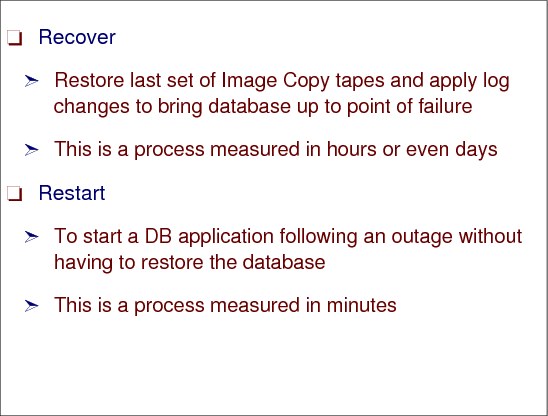
Figure 7-11 Database restart versus recovery
Database restart versus recovery
The ability to do a database restart, rather than a database recovery, is essential to meet the recovery time objective (RTO) of many businesses – typically less than an hour. Database restart allows starting a database application (as you would do following a database manager, or system abend) without having to restore it from backups.
Recovery
Database recovery is normally a process measured in many hours (especially if you have hundreds or thousands of databases to recover), and involves restoring the last set of image copies and applying log changes to bring the database up to the point of failure. But there is more to consider than simply the data for one data manager. What if you have an application that updates data in IMS, DB2, and VSAM? If you need to do a recover for these, will your recovery tools not only allow you to recover them to the same point in time, but also to the level of granularity that ensures that either all or none of the updates made by one transaction are recovered? Being able to do a restart rather than a recover avoids these issues.
Restart
Data consistency across all primary and secondary volumes spread across any number of storage (both tape and disk) subsystems is essential to provide not only data integrity, but also the ability to do a normal database restart in the event of a disaster. Restart is just the restart of the DB application after the outage using the mirrored database on the secondary subsystem. This usually takes minutes, and does not require taking further time-consuming recovery steps.
7.12 GDPS introduction

Figure 7-12 GDPS introduction
GDPS introduction
Geographically Dispersed Parallel Sysplex (GDPS) is a multi-site application availability solution that provides the capability to manage remote copy configuration and storage subsystems, automates Parallel Sysplex operational tasks, and performs failure recovery from a single point of control, thereby improving application availability and decreasing RTO figures.
The considerations for a multi-site sysplex depend on whether you plan to run production systems in both sites at the same time, or if all the production systems will be in a single site at any one time. Configurations where production systems can run in both sites at the same time are referred to as multi-site workload configurations. Configurations where the production systems run together in one site or the other (but not split between multiple sites) are referred to as single-site workload configurations or sometimes as “active/standby” configurations. Other variations on this, where production systems are predominantly running at one site, but where partially active systems or systems only enabled for queries are running at the other site, are still multi-site workloads.
Minimize impact of failures
GDPS is designed to minimize the impact of any failure, including disasters or a planned site outage. It provides the ability to perform a controlled site switch for both planned and unplanned site outages, with almost no data loss, maintaining full data integrity across multiple volumes and storage subsystems, and the ability to perform a normal Data Base Management System (DBMS) restart (not DBMS recovery) at the other site.
The majority of outages are indeed planned, and even among unplanned outages, the majority are not disasters. However, in the current business world of 24x7 Internet presence, and web-based services shared across and also between enterprises, even planned outages can be a serious disruption to your business. Unplanned outages are unexpected events. Examples of unplanned outages are software or hardware failures. Some of these outages may be quickly recovered from, but others may be considered a disaster.
You will undoubtedly have both planned and unplanned outages while running your organization, and your business resiliency processes must cater to both types. You will likely find, however, that coordinated efforts to reduce the numbers of and impacts of unplanned outages often are complementary to doing the same for planned outages.
GDPS and applications
GDPS is application independent, thereby covering your total application environment. GDPS is enabled by means of the following key IBM technologies:
•Parallel Sysplex, but could be base Sysplex
•Tivoli NetView for z/OS
•System Automation for OS/390
•IBM TotalStorage® Enterprise Storage Server® (ESS) or DS8000®
•Peer-to-Peer Virtual Tape Server (PtP VTS)
•Optical Dense Wavelength Division Multiplexer (DWDM)
•Peer-to-Peer Remote Copy (PPRC) architecture - also named Metro Mirror in DS8000 terms
•Extended Remote Copy (XRC) architecture - also named Global Mirror in DS8000 terms
•Virtual Tape Server Remote Copy architecture
GDPS support for PPRC and XRC
GDPS supports both the synchronous (PPRC) as well as the asynchronous (XRC) forms of remote copy. It also supports the PtP VTS form of remote copying tape data.
PPRC (Metro Mirror) is a hardware solution that synchronously mirrors data residing on a set of disk volumes, called the primary volumes in Site 1, to secondary disk volumes on a second system in Site 2. Only when the primary storage subsystem receives "write complete" from the secondary storage subsystem is the application I/O write signaled completed.
XRC (Global Mirror), on the other hand, is a combined hardware and software asynchronous remote copy solution. The application I/O write is signaled completed when the data update to the primary storage is completed. Subsequently, a DFSMSdfp component called System Data Mover (SDM), asynchronously off loads data from the primary storage subsystem’s cache and updates the secondary disk volumes.
For more information, refer to the GDPS home page at:
|
Terminology note: In this book we continue to use the term Peer-to-Peer Remote Copy (PPRC) when referring to the synchronous disk replication architecture. The rebranded name of the IBM implementation of this architecture is IBM Metro Mirror, which will be used when specifically referring to the IBM implementation on the IBM Enterprise Storage Server (ESS) and the IBM DS8000 family of products. Similarly, we continue to use the term eXtended Remote Copy (XRC) when referring to the asynchronous disk copy technology that leverages the z/OS System Data Mover (SDM). The rebranded name of the IBM disk storage implementation is z/OS Global Mirror, which will be used specifically when referring to the IBM implementation on the IBM Enterprise Storage Server (ESS) and the IBM DS8000 family of products.
|
7.13 GDPS overview
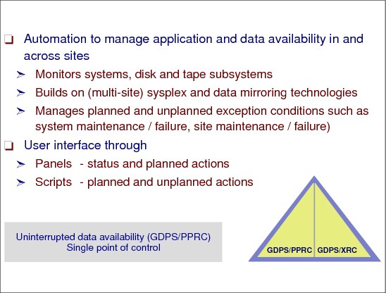
Figure 7-13 GDPS overview
GDPS overview
The main purpose of GDPS is to provide a disaster recovery solution mainly based on remote copy technology. There are several standard SW products to enable GDPS acting as a controlling system. One part of GDPS is the automation that ensures consistency across any number of disk subsystems.
Automation
Automation is responsible for monitoring systems, DASD, and tape subsystems across recovery sites, and taking action according to defined script rules if any exception condition is detected. GDPS is also able to manage planned conditions like system and site maintenance by providing a user interface.
User interface
There are two primary user interface options available for GDPS/PPRC, the NetView 3270 panels and a browser-based graphical user interface.
An example of the main GDPS/PPRC 3270-based panel is shown in Figure 7-14 on page 310. This panel is relatively simple to use, with a summary of configuration status at the top of the panel and a menu of choices that a user can select from below. As an example, a user would simply type a 1 at the Selection ===> prompt and press Enter to view the disk mirroring (“DASD Remote Copy”) panels.
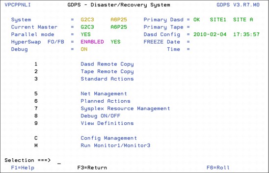
Figure 7-14 Main GDPS/PPRC 3270-based panel
GDPS operational interfaces
GDPS provides operation interfaces such as the following:
•DASD remote copy panels
– Provide information about DASD remote copy status
– Provide a manual operation interface for the remote copy DASD configuration
•Tape remote copy panels
– Provide manual control of the GDPS peer-to-peer virtual tape server (PtPVTS)
•GDPS action panels with main operator interface for starting, stopping, and restarting systems.
•GDPS sysplex resource management panels to control CF structures and couple data sets.
7.14 Need for data consistency
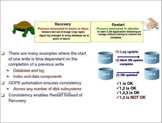
Figure 7-15 Need for data consistency
Need for data consistency
Data consistency across all primary and secondary volumes spread across any number of storage subsystems is essential for providing the ability to keep data integrity and allowing a normal database restart in the event of a disaster.
Dependent write logic
Database applications commonly ensure the consistency of their data by using dependent write logic irrespective of whether remote data mirroring is being used. Dependent write logic states that if I/O B must logically follow I/O A, then B will not be started until A completes successfully. This logic would normally be included in all software to manage data consistency. There are numerous instances within the software subsystem itself, such as databases, catalog/VTOC, and VSAM file updates, where dependent writes are issued.
It is unlikely that all the components in a data center would fail at the same instant – even in the rare case of a full data center outage. The networks may fail first, or possibly one disk subsystem, or any other components in unpredictable combinations. No matter what happens, the remote image of the data must be managed such that cross-volume and subsystem data consistency is preserved during intermittent and staged failures that might occur over many seconds, even minutes. Such a staged failure is generally referred to as a “rolling disaster.”
Data consistency
Data consistency during a rolling disaster is difficult to achieve for synchronous forms of remote copy because synchronous remote copy is entirely implemented within disk subsystem pairs. Data consistency means that, from an application’s perspective, the secondary disks contain all updates until a specific point in time, and no updates beyond that specific point in time; in other words, the time sequence of the writes was respected when remotely copied. In a disaster recovery it is possible to loose some data updates in the secondary copy but it is not acceptable to not have data consistency.
For example, in Figure 7-15 on page 311 the synchronously mirrored data sets are spread across multiple disk subsystems for optimal performance. The volume containing the DBMS log on the LOG-P disk subsystem in Site1 is mirrored to the secondary volume in the LOG-S disk subsystem in Site2, and the volume containing the data segments in the DB-P disk subsystem in Site1 is mirrored to the secondary volume in the DB-S disk subsystem in Site2. Assume that a disaster is in progress in Site1, causing the link between DB-P and DB-S to be lost before the link between LOG-P and LOG-S is lost. With the link between DB-P and DB-S lost, a write sequence of (1), (2), and (3) might be completed on the primary devices (depending on how the remote copy pair was defined) and the LOG writes (1) and (3) would be mirrored to the LOG-S device, but the DB write (2) would not have been mirrored to DB-S. A subsequent DBMS restart using the secondary copy of data in Site2 would clean up in-flight transactions and resolve in-doubt transactions, but the missing DB write (2) would not be detected. In this example of the missing DB write the DBMS integrity was compromised.
The fact that the secondary copy of the data is data consistent means that applications can be restarted in the secondary location without having to go through a lengthy and time-consuming data recovery process, that implies backups being restored.
GDPS automation
The main focus of GDPS automation is to make sure that, whatever happens in Site 1, the secondary copy of the data in Site 2 is data consistent (the primary copy of data in Site 1 will be data consistent for any Site 2 failure).
GDPS/PPRC
GDPS/PPRC uses a combination of storage subsystem and Parallel Sysplex technology triggers to capture a data consistent secondary site copy of the data, using the PPRC freeze function at the first indication of a potential disaster in the primary site.
The PPRC Critical attribute has two values: Yes and No. Yes means that if there is an error along PPRC mirroring (in the link or in the secondary controller) the application executing the write receives back a status of unrecoverable I/O error in the write operation. For NO, the primary controller generates an extended long busy interrupt to be processed just by IOS. See “An example of write dependency” on page 313 to understand better this action.
The GDPS freeze function, initiated by automated procedures, is designed to freeze the image of the secondary data at the very first sign of a disaster in the primary. This prevents the logical contamination of the secondary copy of data that would occur if any storage subsystem mirroring were to continue after a failure that prevents some, but not all, secondary volumes from being updated.
Data consistency in a GDPS/XRC environment is provided by the Consistency Group (CG) processing performed by the System Data Mover (SDM). The CG contains records that have their order of update preserved across multiple Logical Control Units within a storage subsystem and across multiple storage subsystems.
Providing data consistency optimizes the secondary copy of data to perform normal restarts (instead of performing database manager recovery actions).
7.15 An example of write dependency
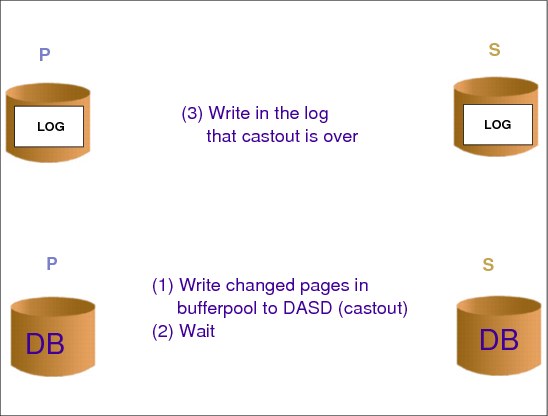
Figure 7-16 An example of write dependency
An example of write dependency
Let us imagine a DB2 scenario where the log and the table spaces are in 3390s located in different physical controllers, as usually recommended. It is time to write the changed pages in the local buffer pool (cast out) to DASD. These 3390s are PPRC remote copied. Another key point is that DB2 is not aware about such copying.
First, DB2 writes pages to the table space in DASD; then enters in wait (to guarantee that the last write was executed); next it writes to the log informing that the cast out was complete. With this procedure (including the wait) DB2 forces the time sequence of writes in primary 3390s.
The last write to the DB and the write to log are time dependent writes and they must be executed exactly in their time sequence. We loose data consistency and consequently integrity if these writes are written out of the time sequence, because we will have an interval where the log is telling that the cast out was complete and it was not.
The challenge with remote copy is to guarantee data consistency in the secondary copy; the DB2 Wait function guarantees it in the primary. This consistency is called secondary consistency. It implies that the time write sequence is respected in the secondary copies. It implies that either both writes are copied, or just the final table space write is copied, or none are copied. Never will we have a case where (even for a short amount of time) just the write to log was copied. There are two ways to guarantee secondary consistency with PPRC: PPRC Critical= No or the GDPS freezing function.
7.16 GDPS terminology

Figure 7-17 GDPS terminology
Controlling system
The controlling system, also known as the K-system, is a system that is in the same sysplex as the production systems, thus, it can see all the messages from those systems that are being managed by GDPS. However, its primary role is to be able to control the recovery following an outage. For this reason, the controlling system resides and has all its DASD in the recovery site, Site 2, and it shares only the couple data sets (CDSs) with other systems in the sysplex.This ensures that the controlling system will not be affected by any events that might impact the availability of the managed systems.
Site 1 and Site 2
In a GDPS/PPRC environment, the site that contains the primary DASD during normal operations is known as Site 1. The site that contains the secondary DASD during normal operations is known as Site 2. The terms Site 1 and Site 2 are used when defining the PPRC DASD to GDPS. If there is a disaster, or a planned site switch, the DASD in Site 2 would become the primary DASD.
Master system
Normally the controlling system is the master system. However, if the controlling system is unavailable for some reason, one of the other systems takes over as the master system. Some GDPS functions (configuration processing, takeover processing, and control script execution) can only be carried out by the master system.
Production system
A production system is a system that normally runs the site’s production workload and updates the primary DASD.
Control script
A control script is like a program, consisting of GDPS-provided functions, that can be manually initiated. Control scripts can do things like IPLing a system, stopping the use of a coupling facility, and so forth.
Batch script
A batch script is similar in concept to a control script. However, while a control script is invoked from the GDPS panels, a batch script is initiated by calling a GDPS-provided routine, either from a batch job, or as a result of messages being issued.
Takeover script
A takeover script is also like a program, again consisting of GDPS-provided functions. Unlike a control script, however, a takeover script can only be initiated following an error that results in a possible takeover situation (for example, a DASD failure or a system failure). Takeover scripts are initiated as a result of messages being issued.
Standard actions
Standard actions are a set of functions that can be performed for z/OS images and LPs using GDPS standard actions, on the GDPS main panel. The standard actions panels should be the main interface for the operator for routine functions such as starting, stopping, and restarting systems when you have GDPS in your production environment.
7.17 GDPS/PPRC
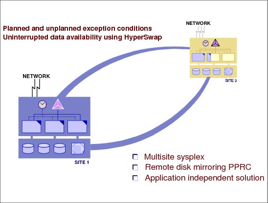
Figure 7-18 GDPS/PPRC
GDPS/PPRC
GDPS/PPRC is one of the GDPS offerings that manages and protects IT services by handling planned and unplanned exception conditions, and maintaining full data integrity across multiple volumes and storage subsystems. By managing both planned and unplanned exception conditions, GDPS/PPRC maximizes application availability and provides business continuity.
Topology
The physical topology of a GDPS/PPRC is shown in Figure 7-18.
GDPS/PPRC consists of a base or Parallel Sysplex cluster spread across two sites (known as Site 1 and Site 2), with one or more z/OS systems at each site.
The multisided Parallel Sysplex cluster must be configured with redundant hardware (for example, a Coupling Facility and a Sysplex Timer, or an STP server, in each site), and the cross-site connections must be redundant.
All critical data resides on storage subsystems in Site 1 (the primary copy of data) and is mirrored to the storage subsystems in Site 2 (the secondary copy of data) via PPRC synchronous remote copy.
7.18 Freeze policy options
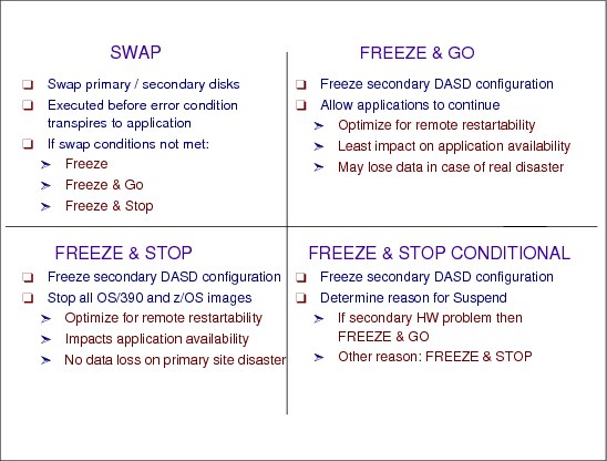
Figure 7-19 Freeze policy options
Freeze policy options
All the following explanations apply when the ESS/DS8000 PPRC option Critical is equal to NO. When Critical=YES, the application issuing the write (this could be DB2) receives back an unrecoverable I/O error status when there is any problem with the PPRC mirroring. With such information the application does not issue the next dependent write operation and then the secondary consistency is guaranteed. However, all the transactions reaching this primary data will abend.
With Critical=NO, the ESS/DS8000 controller generates the extended long busy (ELB) interrupt when the remote copy is not possible. (Maybe the problem in the link is the start of a rolling disaster.) IOS in z/OS catches the interrupt and issues a message in console, that is caught by the GDPS automation process.
When the remote copy in a primary volume is suspended (with Critical=NO) because of an error condition in the remote copy, the GDPS automation routines immediately freeze the image of all the required secondary volumes, applying the CGROUP FREEZE command to all application-related LSSs that are known to GDPS. This preserves the consistency of the recovery data at that specified point in time. Imagine that the DB2 table space write remote copy failed; then the log remote copy must be frozen to guarantee the secondary consistency when DB2 writes to the log. In this case, the primary DB and log are updated and the secondary DB and log are not.
After freezing, GDPS does an analysis step. The analysis is driven by a predetermined installation policy, which can be either FREEZE and GO, or FREEZE and STOP, or FREEZE and STOP CONDITIONAL. They are described in the following paragraphs.
FREEZE and GO
With this option the automation routines allow applications to continue after the secondary volumes have been frozen. The implication is that updates to primary volumes after the freeze will be lost if a disaster occurs, and thus applications will have to be restarted in the recovery site. The other implication is that the availability of the application is favored, as it is not stopped by this error circumstance.
FREEZE and STOP
With this option the automation routines stop all applications right where they are at the time of freezing the secondary volumes. Application availability will be impacted, but the currency of the recovery site data is preserved.
FREEZE and STOP CONDITIONAL
With this option the automation routines freeze the image of the secondary volumes, and then analyze the reason for the suspend condition. If it turns out to be nonthreatening, for instance, because a secondary piece of equipment has failed, then the applications will be allowed to continue. However, if there is any indication of a serious problem, the automation routines will then stop all the required applications.
There is a difference between using CRIT=YES or Freeze automation, as described here.
If you have CRIT=YES option
The sequence of events is:
•The controller returns a unit check (unrecoverable I/O error) to the DB2.
•DB2 enters on the log the fact that this table space on the first 3390 requires recovery.
•Since the primary 3390 containing the log does not appear to have a mirroring problem, this log information gets mirrored to the secondary.
•Now, the primary site fails, so GDPS recovers the secondary 3390s and restarts your systems using these disks
•DB2 will force table space recovery on this table (and probably many others) because of the information in the log.
If you have Freeze automation
The sequence of events is:
•The controller returns an extended long busy (ELB) status to z/OS and issues a console message.
•GDPS automation captures this message and issues the CGROUP FREEZE command against all PPRC SSIDs; CGROUP FREEZE severs all PPRC links.
•The primary site comes tumbling down so GDPS recovers the secondary 3390s and restarts your systems using these disks.
•There is no log information about I/O errors and the restart is very simple.
So as you can see, with CGROUP FREEZE we do not have to run any lengthy forward recovery, whereas with CRIT=Y we do.
7.19 Planned reconfiguration support
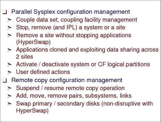
Figure 7-20 Planned reconfiguration support
Planned reconfiguration support
GDPS/PPRC planned reconfiguration support automates procedures performed by an operations center. In addition to the disaster recovery and planned reconfiguration capabilities, GDPS/PPRC also provides a much more user-friendly interface for monitoring and managing the remote copy configuration. These include standard actions to do the tasks described in this section.
Parallel Sysplex configuration management
Coupling links are required in a Parallel Sysplex configuration to provide connectivity from the z/OS images to the Coupling Facility. Coupling links are also used to transmit timekeeping messages when Server Time Protocol (STP) is enabled. If you have a multi-site Parallel Sysplex, you will need to provide coupling link connectivity between sites.
These are the recovery actions related to Parallel Sysplex:
•Recreate the couple data sets or change the policies.
•Quiesce a system’s workload and remove the system from the Parallel Sysplex cluster (for example, stop the system prior to a change window).
•Remove a site without stopping applications by using the HyperSwap® functionality. The applications must be cloned and exploiting data sharing across two sites, and the network must be switchable if the applications use it.
•IPL a system (for example, start the system after a change window).
•Quiesce a system’s workload, remove the system from the Parallel Sysplex cluster, and re-IPL the system (for example, recycle a system to pick up software maintenance).
Remote copy configuration management
These are the recovery actions related to remote copy, such as Initialize and monitor a remote copy volume pair based upon policy, and perform routine operations on installed storage subsystems, both disk and tape.
Standard actions can be initiated against a single system or a group of systems.
Additionally, GDPS/PPRC provides customized scripting capability for user-defined actions (for example, planned site switch in which the workload is switched from processors in Site 1 to processors in Site 2).
In order for GDPS to manage the remote copy environment, you must first define the configuration (primary and secondary LSSs, primary and secondary devices, and PPRC links) to GDPS in a file called the GEOPARM file. After the configuration is known to GDPS, you can use the panels to check that the current configuration matches the desired one. You can start, stop, suspend, and resynchronize mirroring at the volume or LSS level. You can initiate a FlashCopy® and you can reverse the direction of mirroring. These actions can be carried out at the device or LSS level, or both, as appropriate.
HyperSwap function
GDPS/PPRC delivers a powerful function known as “HyperSwap.” HyperSwap provides the ability to non-disruptively switch from using the primary volume of a mirrored pair to using what had been the secondary volume. Prior to the availability of HyperSwap, an IPL was required on every system if you wanted to switch and run from the secondary volumes, meaning that it was not possible to maintain application availability across a switch from primary to secondary volumes.
With HyperSwap, such a move can be accomplished without IPL and with just a brief hold on application I/O. The HyperSwap function is designed to be completely controlled by automation, thus allowing all aspects of the site switch to be controlled via GDPS.
7.20 Unplanned reconfiguration support
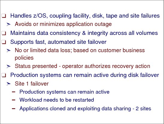
Figure 7-21 Unplanned reconfiguration support
Unplanned reconfiguration support
GDPS/PPRC unplanned reconfiguration support not only automates procedures to handle site failures, but can also minimize the impact and potentially mask a z/OS system, processor, Coupling Facility, disk or tape failure, based upon GDPS/PPRC policy.
If z/OS fails, the failed system and workload can be automatically restarted.
Server failures
If a server fails, the failed systems and their workload can be restarted on other servers. If the primary disk storage subsystem fails, a disk reconfiguration will allow access of the secondary PPRC volumes, which contain mirrored data consistent with the primary data. The following tasks can be executed:
•Present actual status to operator
•Request failover authorization
•Remove systems from Parallel Sysplex
•Perform disk reconfiguration
•Perform tape reconfiguration
•Perform CBU activation
•Perform CF reconfiguration
•Perform CDS reconfiguration
•Acquire processing resources and IPL systems into Parallel Sysplex
•Initiate application startup
Disk failover
When a primary disk failure occurs and the disks are switched to the secondary devices, PPRC Failover/Failback (FO/FB) support eliminates the need to do a full copy when reestablishing replication in the opposite direction. Because the primary and secondary volumes are often in the same state when the freeze occurred, the only differences between the volumes are the updates that occur to the secondary devices after the switch. Failover processing sets the secondary devices to primary suspended status and starts change recording for any subsequent changes made. When the mirror is re-established with failback processing, the original primary devices become secondary devices and a resynchronization of changed tracks takes place.
|
Note: All disk subsystems in your GDPS configuration, in both Site1 and Site2, must support PPRC Failover/Failback for GDPS to exploit this capability.
|
Site 1 failover
An existing GDPS script that previously performed failover and restart of System z resources can be extended to also include statements to automate the failover of SA AppMan clusters to Site2. When the additional script statements are executed as part of the site takeover script, GDPS automation performs the following actions to move System z resources from Site1 to Site2:
•It resets production systems in Site1.
•It reconfigures the secondary disks.
•It activates CBU for servers in Site2.
•It switches couple data sets to those in Site2.
•It activates partitions in Site2.
•It reIPLs P1, P2, and P3 in Site2.
|
Note: GDPS/GM V3.6 has been enhanced to provide DCM support for VCS clusters. Distributed Cluster Management (DCM) is a GDPS capability introduced in GDPS V3.5 which allows the management and coordination of planned and unplanned outages across distributed servers which might be clustered using clustering solutions, and the System z workloads that GDPS is responsible for. DCM support was initially introduced in GDPS/PPRC V3.5 and GDPS/XRC V3.5. The support in GDPS V3.5 was for distributed clusters managed by Veritas Cluster Server (VCS) and IBM Tivoli System Automation Application Manager (SA AppMan).
|
7.21 GDPS/PPRC prerequisites
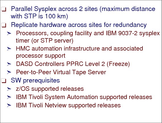
Figure 7-22 GDPS/PPRC prerequisites
GDPS/PPRC prerequisites
The prerequisites for GDPS/PPRC are described in this section.
Parallel Sysplex across two sites
PPRC is the IBM synchronous remote copy technology. When an application issues a write to a PPRC device, the I/O request does not complete until the write request has been successfully sent to the remote (secondary) control unit. PPRC is a HW-based solution that consists of a primary control unit connected to a secondary in different sites. Site 1 and 2 (this is GDPS site terminology) must have z/OSs in the same Parallel Sysplex (or Base Sysplex). This requirement limits the distance for PPRC to about 100 km. However, at such distance the PPRC performance will adversely affect applications.
Replicate hardware across sites for redundancy
As a minimum GDPS requirement, you must define a cross-site Parallel Sysplex, which means the HW must be replicated on Site 1 and Site 2. The following HW should be available or is optional depending on the environment:
•CPCs, coupling facilities
•Sysplex Timer or STP servers
•HMC automation infrastructure
•Disk subsystems supporting PPRC level 2 freeze function
•Peer-to-peer virtual tape server
•Dense wavelength division multiplexors (DWDMs)
Software prerequisites
Following are the software prerequisites:
•Installation Services Prerequisites for GDPS/PPRC
– Generally supported release of z/OS or z/OS.e
– Generally supported release of IBM Tivoli Netview
– Generally supported release of IBM Tivoli System Automation for z/OS
– Storage Subsystems with PPRC CGROUP Freeze/Run support
– Multisite Base or Parallel Sysplex (1)
|
Note: Certain GDPS configurations may not require a cross-site sysplex.
|
•Optional - Prerequisites for GDPS / PPRC Multiplatform Resiliency for System z support:
– Generally supported release of z/VM
– Linux on System z
– Generally supported release of IBM Tivoli System Automation for Multiplatforms
– IBM Tivoli System Automation for Multiplatforms XDR for Linux on System z
•Optional - Prerequisites for GDPS FlashCopy support:
– Storage subsystems with FlashCopy support
•Optional - Prerequisites for GDPS Open LUN support:
– IBM Tivoli Netview for z/OS V5.1 (or later)
– Storage subsystems with support for:
• Open PPRC Management via CKD device addresses
• Open PPRC SNMP alerts
– CKD utility device (that is, CKD LSS) on the disk subsystems that house the distributed LUNs.
•Optional - Prerequisites for GDPS HyperSwap:
– Storage subsystems with Extended CQUERY support
– PPRC Failover/Failback support required for additional HyperSwap performance for planned swaps and to avoid initial copy following an unplanned swap
•Optional - Prerequisites for GDPS DCM for Veritas Cluster Server:
– Veritas Cluster Server HA/DR 5.0 package or later
– Tivoli NetView for z/OS V5.2 or later
– Distributed server hardware, the operating system release and service levels supported by Veritas Cluster Server
•Currently supported releases of Tivoli products can be found in:
– Tivoli product lifecycle dates
•Currently supported releases of z/OS and z/OS.e can be found in:
– z/OS support
7.22 GDPS/XRC

Figure 7-23 GDPS/XRC
GDPS/XRC
Extended Remote Copy (XRC), rebranded to IBM System Storage® z/OS Global Mirror, is a combined hardware and software asynchronous remote copy solution. Consistency of the data is maintained via the Consistency Group function within the z/OS System Data Mover (SDM).
Because of the asynchronous nature of XRC, it is possible to have the secondary disk at greater distances than would be acceptable for PPRC. Channel extender technology can be used to place the secondary disk up to thousands of kilometers away. Because XRC is asynchronous, the impact it has on response times is minimal, and is independent of the distance between the primary and secondary volumes.
GDPS/XRC combines the benefits of GDPS with the extended distance capabilities of XRC. It includes automation to manage remote copy pairs and automates the process of recovering the production environment with limited manual intervention, including invocation of CBU1, thus providing significant value in reducing the duration of the recovery window and requiring less operator interaction.
GDPS offering
GDPS/XRC is a GDPS offering that provides the automation for planned and unplanned reconfiguration support, the primary attribute of most D/R solutions. The physical topology of a GDPS/XRC (see Figure 7-23) consists of production systems in Site 1 (the production systems could be a single system, multiple systems sharing disks, or a base or Parallel Sysplex cluster). Note that the Parallel Sysplex cluster does not span Sites 1 and 2. Site 2 (the recovery site) can be located at virtually any distance from Site 1 (the production site). During normal operations, the XRC System Data Mover (one or more) will be executing in Site 2 and is in a base sysplex with the GDPS controlling system (refer to “GDPS terminology” on page 314 for a definition of the GDPS controlling system).
All critical data resides on storage subsystems in Site 1 (the primary copy of data) and is mirrored to the storage subsystems in Site 2 (the secondary copy of data) via XRC asynchronous remote copy.
SDM in recovery site
The following planned reconfiguration actions are provided by GPDPS/XRC for the SDM in the recovery site:
1. Quiesce a system’s workload and remove the system from the Parallel Sysplex cluster (for example, stop the system prior to a change window).
2. IPL a system (for example, start the system after a change window).
3. Quiesce a system’s workload, remove the system from the Parallel Sysplex cluster, and re-IPL the system (for example, recycle a system to pick up software maintenance).
Planned Actions with XRC and FlashCopy
Planned Actions are GDPS scripts that are initiated from the GDPS panels (option 6 on the main GDPS panel, as shown in Figure 5-3 on page 106). A Planned Action script might consist of a number of tasks. For example, you could have a script that would stop an LPAR, change its IPL address to the alternate SYSRES, and then re-IPL it, all from a single script.
A more complex example of a Planned Action is when a single action in GDPS results in a tertiary copy of the secondary disks being taken, followed by IPLing the “production” systems in LPARs in the recovery site. This allows you to test your recovery procedures while XRC sessions between the primary to the secondary volumes are running, and you maintain up-to-date disaster readiness. Specifically, the following actions are carried out by GDPS in this script:
• Zero Suspend FlashCopy is initiated:
– This prevents the SDMs from writing new consistency groups to the secondary disks.
– A FlashCopy is taken of all XRC secondary devices, as well as the devices that house the XRC state, control, and journal data sets.
– Zero Suspend FlashCopy completes and SDM processing resumes writing new consistency groups to the secondary disks.
•An XRC recover on the tertiary devices is run.
•The CBU capacity reserved PUs on CPCD are activated.
•Any test systems whose LPARs would be used for a production system in case of a disaster are deactivated.
•The CF LPARs and the LPARs that will contain the recovered production systems are activated, followed by an IPL of those systems.
So, the result of a single action on your behalf (initiating the Planned Action) is that you have created a copy of your production system that can be used for DR testing, you have brought up recovery versions of your production systems, and you have maintained disaster readiness by still having synchronization between the primary and secondary volumes.
7.23 GDPS/XRC prerequisites

Figure 7-24 GDPS/XRC prerequisites
GDPS/XRC prerequisites
Figure 7-24 shows the prerequisites for GDPS/XRC. The HW and SW products must be installed and customized prior the start of GDPS implementation. GDPS will run on every system of the recovery side, so it is vital that all systems adhere to these requirements. There is no need for HyperSwap with GDPS/XRC because the secondary volumes are online in the secondary site.
•Installation services prerequisites for GDPS/XRC:
– Generally supported release of z/OS or z/OS.e
– Generally supported release of IBM Tivoli Netview (Enterprise or Procedural level)
– Generally supported release of IBM Tivoli System Automation for z/OS
– Storage Subsystems (Primary) with XRC support
– Base or Parallel Sysplex in recovery site between K-sys and SDMs
•Optional prerequisites for GDPS FlashCopy support:
– Storage subsystems with FlashCopy support
•Optional prerequisites for Linux on z/OS support:
– SuSE SLE8+ Linux for System z
•Optional prerequisites for GDPS DCM for Veritas Cluster Server:
– Veritas Cluster Server HA/DR 5.0 package or later
– Tivoli NetView for z/OS V5.2 or later
– Distributed server hardware, the operating system release and service levels supported by Veritas Cluster Server
GDPS/XRC summary
GDPS/XRC is a powerful offering that provides an industry-leading, long distance, disaster recovery capability. It is based on the XRC technology, which is highly scalable (there are customers with close to 20,000 volumes being remote copied by XRC). XRC is industry-proven, having been available for well over a decade. XRC also has interoperability advantages: it is possible to have different disk subsystem types, and even different vendors, for the primary and secondary devices.
Building on the base of XRC, GDPS adds the powerful script capability that allows you to perfect the actions to be taken, either for planned or unplanned changes, eliminating the risk of human error. Combining its support of FlashCopy with the scripting capabilities significantly reduces the time and complexity to set up a disaster recovery test. And anyone who has been involved in DR planning will confirm that one of the most important factors in a successful disaster recovery process is frequent and realistic testing that is tied into your change management system. Having the ability to test your DR capability any time a significant change is implemented ensures that all aspects of application management are addressed.
In addition to its disaster recovery capability, GDPS/XRC also provides a much more user-friendly interface for monitoring and managing the remote copy configuration. This includes the initialization and monitoring of the XRC volume pairs based upon policy and performing routine operations on installed storage subsystems.
7.24 GDPS HMC automation interface
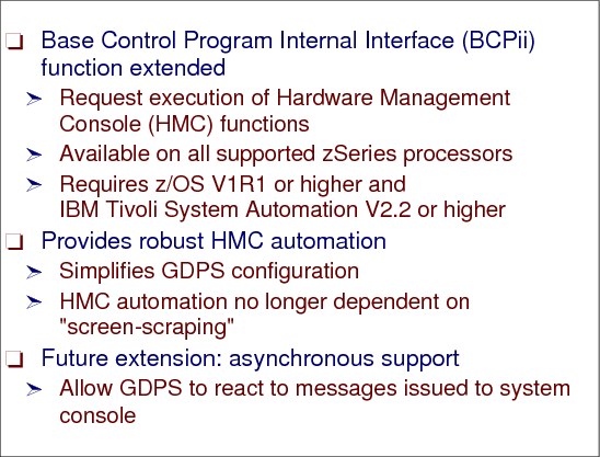
Figure 7-25 HMC automation interface
GDPS HMC automation interface
GDPS requires the automation products listed in Figure 7-25 to be installed on all systems in the GDPS complex. GDPS depends on the application startup and the system shutdown sequences to be fully automated through an automation product.
HMC and consoles
To be able to control the processors in the remote center, you need to have access to the LAN containing the SEs and HMCs for the processors in that location. Such connectivity is typically achieved using bridges or routers. If you are running systems at the remote site, you will also want to be able to have consoles for those systems. Two options are 2074 control units and OSA-ICC cards. Alternatively, you could use SNA consoles; however, be aware that they cannot be used until VTAM is started, so they cannot be used for initial system loading.
Tivoli products
The GDPS automation code relies on the runtime capabilities of Tivoli NetView and Tivoli System Automation (SA). While these products provide tremendous first level automation capabilities in and of themselves, there are alternative solutions you may already have from other vendors. GDPS continues to deliver features and functions that take advantage of properties unique to the Tivoli products (like support for alert management through Tivoli IOM), but Tivoli NetView and Tivoli SA also work very well alongside other first level automation solutions. In other words, while there are indeed advantages to a comprehensive solution from IBM, you do not have to replace your current automation investments before moving forward with a GDPS solution.
Screen-scraping
“Screen scraping” does not work well with the 3270 block mode, so the OSA-ICC is expanded to include 3215 support on the z9 EC and BC and all newer processors as a PPRQ.
GDPS messages
Automation of NIP messages through the BCPii is contingent on no NIP console devices being active during IPL of a system. If there is an active NIP console device, the messages will be sent to this device and will not be automated.
To ensure that the NIP automation is successful, you have two options:
•Do not define any NIPCONS devices in your HCD definitions for the systems in your GDPS (neither for production systems nor for controlling systems). This will guarantee that the NIP messages are intercepted by the BCP Internal Interface and are sent to SYSCONS for automation. However, if you select to do this, you must ensure that the operators that perform IPLs have access to the HMC. This will allow the operators to troubleshoot in case an IPL appears to be hung for some reason.
•To use GDPS NIP console monitoring, a user must not have an active console at IPL time, thereby enabling the NIP messages to flow to GDPS via the BCPii SYSCONS interface. If a console previously defined as OFFLINE at IPL was changed to ONLINE at IPL, or if a console was recently installed at an MVS address corresponding to a NIP console (and that console is available at IPL time), then the GDPS NIP message monitoring is not operational, which can cause this GEO280A message since the external console would receive the NIP messages, thereby preventing them from being delivered across the BCPii to GDPS.
7.25 Peer-to-Peer Remote Copy (PPRC)
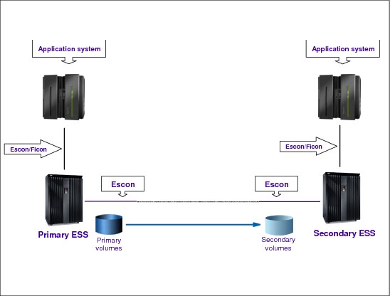
Figure 7-26 Peer-to-Peer Remote Copy
Peer-to-Peer Remote Copy (PPRC)
Here we summarize the Peer-to-Peer Remote Copy. PPRC (also called Metro Mirror in DS8000) is a hardware solution that enables the shadowing (mirroring) of data from one site and its associated DASD volumes (the primary volumes) to a second system at another site (the recovery system) and its DASD volumes (the secondary volumes).
Updates made on primary DASD volumes are synchronously shadowed onto secondary DASD volumes. The application write operation is only completed when data is secure on the secondary site. It is used primarily as part of the business continuance solution for protecting the organization’s data against disk storage subsystem loss or complete site failure.
PPRC connectivity options
Connectivity between the primary and secondary disk subsystems can be provided by direct connections between the primary and secondary disk subsystems, by FICON switches, by DWDMs, and by channel extenders. The type of inter-site connection (dark fiber or telecommunications link) available determines the type of connectivity you use:
•Telecommunication links can be used by channel extenders.
•Other types of connectivity require dark fiber.
In a DS8000 the connection between the two controllers is through FCP links with an aggregate data rate of 200 MB/sec. For larger distances you might need:
•Channel Extenders over wide area network (WAN) lines
•Dense Wave Division Multiplexors (DWDM) over dark fibers
PPRC connectivity considerations
We have the following connectivity considerations:
•PPRC synchronous (SYNC) maximum supported distance is 300 km, but much less than this we have performance issues.
The maximum distance supported for IBM Metro Mirror is 300 km (without an RPQ). Note that typical GDPS/PPRC and GDPS/HyperSwap manager configurations are limited to distances less than this due to Coupling Link or timer configurations. Additionally, you will need to contact other storage vendors (if required) to understand the maximum distances supported by their PPRC-compatible mirroring implementations.
|
Note: References to Metro Mirror were replaced by PPRC when discussing IBM’s synchronous mirroring architecture. The brand name of IBM Metro Mirror continues to be used for the implementation of the PPRC architecture included on the IBM Enterprise Storage Server (ESS) and DS8000 family of storage products. A similar change was made for XRC and the IBM brand name of z/OS Global Mirror.
|
•The connectivity infrastructure is transparent to PPRC.
•Evaluation, qualification, approval, and support of PPRC configurations using channel extender products, is the sole responsibility of the channel extender vendor.
•The channel extender vendors and DWDM vendors should be consulted regarding prerequisites when using their products.
7.26 PPRC data flow

Figure 7-27 PPRC data flow
PPRC data flow
A PPRC data copy to the secondary ESS (or DS8000) is done synchronously as part of the primary volume’s update I/O operation. When the application performs a write update operation upon a primary volume, this is what happens:
1. Write to the primary volume (disk subsystem cache and Non-Volatile Store (NVS)). Your production system writes data to a primary volume and a cache hit occurs.
2. Write to the secondary (disk subsystems cache and NVS). The primary disk subsystem’s microcode then sends the update to the secondary disk subsystem’s cache and NVS.
3. Signal write complete on the secondary. The secondary disk subsystem signals write complete to the primary disk subsystem when the updated data is in its cache and NVS.
4. Post I/O complete. When the primary disk subsystem receives the write complete from the secondary disk subsystem, it returns Device End (DE) status to your application program. At this point, the application program can continue its processing, and move on to any dependent writes that might have been waiting for this one to complete.
PPRC data consistency
PPRC on its own only provides consistency for a single write. Guaranteeing consistency across multiple logical subsystems and even across multiple disk subsystems requires automation on top of the PPRC function itself. This is where GDPS comes in with Freeze automation.
|
Note: GDPS uses automation, keyed off events or messages, to stop all mirroring when a remote copy failure occurs. In particular, the GDPS automation uses the IBM PPRC CGROUP FREEZE and CGROUP RUN commands, which have been implemented as part of Metro Mirror and also by other enterprise disk vendors. In this way, as long as the disk hardware supports CGROUP FREEZE/RUN commands, GDPS can ensure consistency across all data in the sysplex (consistency group) regardless of disk hardware type. This preferred approach differs from proprietary hardware approaches that only work for one type of disk hardware.
|
PPRC synchronous technique
This synchronous technique of PPRC ensures that application-dependent writes will be applied in the secondary volumes in the same sequence as in the primary volumes, thus providing application consistency at the recovery site at every moment. If during the process an error occurs that prevents the secondary copy from being updated, PPRC automatically suspends the mirroring function and applies the PPRC CRITICAL attribute behavior. Refer to “An example of write dependency” on page 313 for further discussion. Also, if the logical paths have been defined with the consistency group option enabled, then an extended long busy condition can be instigated that will allow for automation routines to take appropriate actions.
7.27 PPRC volume states - synchronous mode of operation

Figure 7-28 PPRC volume states - synchronous mode of operation
PPRC volume states - synchronous mode of operation
In order to manage PPRC configurations, you need to know the state of the PPRC volumes. You can convert PPRCOPY volume pairs from PPRCOPY extended distance mode to synchronous mode, and vice versa, on regular PPRCOPY pairs as well as on cascaded pairs. A switch to synchronous mode can be done using the PPRCOPY ESTPAIR command while the volume pair is active or after the volume pair has been suspended. As Figure 7-28 shows, at any given time a volume can be in either of the following states:
Simplex The initial state of a volume. A PPRC volume pair relationship has not been established yet between the primary and the secondary volumes.
Pending The initial state of a defined PPRC volume pair relationship, when the initial copy of the primary volume to the secondary volume is happening. This state is also found when a PPRC volume pair is re synchronized after it was suspended. During the pending period, PPRC is copying tracks from the primary to the secondary volume. The volume pair is not in synchronization.
Duplex The state of a PPRC volume pair after PPRC has fully completed the copy operation of the primary volume onto the secondary volume. At this moment the volume pair is in synchronization, and all write updates to the primary volume are synchronously applied onto the secondary volume.
Suspended In this state of the PPRC pair, the writes to the primary volume are not mirrored onto the secondary volume. The secondary volume becomes out of synchronization. During this time PPRC keeps a bit map record of the changed tracks in the primary volume. Later, the volume pair can be re synchronized, and then only the tracks that were updated will be copied. A PPRC volume pair will automatically go into a suspended state, for instance, when the primary ESS cannot complete a write operation to the recovery system ESS. Also, the operator can suspend pairs by command or using the ESS Copy Services WUI.
|
Note: You can convert PPRCOPY volume pairs from PPRCOPY extended distance mode to synchronous mode and vice versa on regular PPRCOPY pairs as well as on cascaded pairs. A switch to synchronous mode can be done using the PPRCOPY ESTPAIR command while the volume pair is active or after the volume pair has been suspended.
|
Monitoring PPRCOPY volume pairs
To monitor the copy process of PPRCOPY volumes, issue the QUERY command. When PPRCOPY extended distance is enabled, you should monitor volumes that have the most out-of-sync tracks waiting to be transmitted because of the delays introduced before updates are received by the recovery site. The amount of data lost during a disaster increases with the number of out-of-sync tracks.
PPRCOPY FAILOVER and FAILBACK
PPRCOPY FAILOVER and FAILBACK allows for reversing the direction of PPRCOPY pairs. The reason you would want to use FAILOVER is to provide access to the data from the secondary site if the primary site fails. When the primary site access is lost, the PPRCOPY ESTPAIR FAILOVER is issued to the original PPRCOPY secondary volumes. If the volumes receiving this command are PPRCOPY secondary volumes, then they must be in the full duplex or suspended state, or a PPRC Extended Distance secondary in duplex pending state.
7.28 GDPS/PPRC HyperSwap

Figure 7-29 GDPS/PPRC HyperSwap
GDPS/PPRC HyperSwap
The GDPS/PPRC HyperSwap function is designed to broaden the continuous availability attributes of GDPS/PPRC solutions by extending the Parallel Sysplex redundancy to disk subsystems. The HyperSwap function can help significantly increase the speed of switching sites and switching disk between sites.
Figure 7-29 illustrates how applications can access the PPRC copy after a HyperSwap via the same set of UCBs. After a data set is allocated by a task, the UCB address cannot be changed. With HyperSwap this UCB, instead of mapping the primary device, now maps the secondary, without any application task disruption.
GDPS/PPRC HyperSwap Manager (GDPS/PPRC HM)
GDPS/PPRC HM is designed to extend the availability attributes of a Parallel Sysplex to disk subsystems, whether the Parallel Sysplex and disk subsystems are in a single site, or the Parallel Sysplex and the primary/secondary disk subsystems span across two sites.
It provides the ability to transparently switch primary disk subsystems with the secondary disk subsystems for either a planned or unplanned disk reconfiguration. It also supports disaster recovery capability across two sites by enabling the creation of a consistent set of secondary disks in case of a disaster or potential disaster. However, unlike the full GDPS/PPRC offering, GDPS/PPRC HM does not provide any resource management or recovery management capabilities.
HyperSwap function
The HyperSwap function is designed to deliver complete automation, allowing all aspects of a site or DASD switch to be controlled via GDPS from a single point of control. Prior to the advent of HyperSwap, DASD could be a single point of failure even when DASDs are mirrored.
In the event that there is a problem writing or accessing the primary disk because of either a primary disk hard failure or because the disk subsystem is not accessible or not responsive, then there is a need to swap from the primary disk subsystems to the secondary disk subsystems.
HyperSwap provides the ability to non-disruptively swap from using the primary volume of a mirrored pair to using what had been the secondary volume. Prior to the availability of HyperSwap, an IPL was required on every system if you wanted to switch and run from the secondary volumes, meaning that it was not possible to maintain application availability across a switch from primary to secondary volumes.
With HyperSwap, such a move can be accomplished without IPL and with just a brief hold on application I/O. The HyperSwap function is designed to be completely controlled by automation, thus allowing all aspects of the site switch to be controlled via GDPS.
7.29 GDPS/PPRC HyperSwap goal
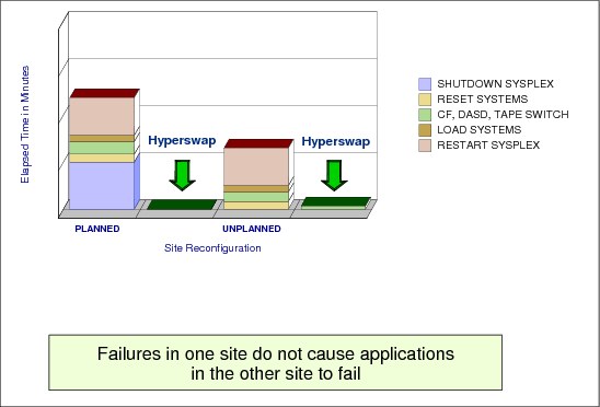
Figure 7-30 GDPS/PPRC HyperSwap goal
GDPS/PPRC HyperSwap goal
The overall availability of your Parallel Sysplex may be significantly improved with HyperSwap. The HyperSwap function delivers significantly faster primary/secondary PPRC DASD swaps both for planned and unplanned DASD reconfiguration activities. The value of HyperSwap can be obtained both in multi-site and single-site environments, as long as DASD is configured to exploit the PPRC function. Prior to HyperSwap, the time to accomplish planned or unplanned switches could take between one and two hours. Most of these activities can virtually be eliminated with HyperSwap, thus reducing the switch time to minutes.
Planned HyperSwap
This allows you to transparently (that is, without having to quiesce the applications) switch primary PPRC disk subsystems with the secondary PPRC disk subsystems for a planned reconfiguration. Planned HyperSwap provides the ability to perform DASD configuration maintenance and planned site maintenance. Large configurations can be supported, because HyperSwap is designed to scale to swap large numbers of disk devices within a few minutes. A planned HyperSwap is invoked manually by operator action using GDPS facilities. One example of a planned HyperSwap would be where a HyperSwap is initiated in advance of planned disruptive maintenance to a disk subsystem.
Unplanned HyperSwap
This delivers the ability for GDPS/PPRC to transparently switch to the secondary PPRC disk subsystems in the event of unplanned outages of the primary PPRC disk subsystems, without data loss and without requiring an IPL. An unplanned HyperSwap is invoked automatically by GDPS, triggered by events that indicate the failure of a primary disk device.
7.30 GDPS/PPRC HyperSwap prerequisites
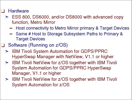
Figure 7-31 GDPS/PPRC HyperSwap prerequisites
GDPS/PPRC HyperSwap prerequisites
GRS star mode must be implemented and all reserves must be converted to global enqueues using conversion RNL definition.
The DASD controller must support PPRC level 3 (extended query function). All 3390 volumes must be in PPRC duplex mode with the exception of the ones containing couple data sets. The PPRC configuration must be symmetric, which means each primary PPRC SSID must have a one-to-one secondary PPRC SSID counterpart.
The HyperSwap devices cannot be shared outside of the sysplex, and all CPCs channels must assure a sufficient bandwidth to primary and secondary subsystems.
The GDPS automation code relies on the runtime capabilities of Tivoli NetView and Tivoli System Automation (SA).
Hardware (ESS and DS8000)
Because Global Mirror is built on Global Copy (PPRC Extended Distance function), any platform that is supported by IBM Metro Mirror is also supported by Global Mirror. Currently this support is limited to the IBM Enterprise Storage Server (ESS) and the IBM DS8000 family of products.
FlashCopy SE is functionally not much different from the standard FlashCopy. The concept of space efficiency with FlashCopy SE relates to the attributes or properties of a DS8000 volume. As such, a space efficient volume could be used like any other DS8000 volume. However, the intended and only recommended use is as a target volume in a FlashCopy relationship.
Additionally, each of the GDPS solutions relies on IBM-developed disk replication technologies: PPRC for GDPS/PPRC, XRC for GDPS/XRC, and Global Mirror for GDPS/GM. These architectures are, of course, implemented on several IBM enterprise storage products. Specifically, PPRC has been implemented and branded as IBM System Storage Metro Mirror for the IBM Enterprise Storage Server (ESS) and the IBM DS8000 family of products. Similarly, the XRC technology has been implemented on the same storage servers under the brand name of IBM System Storage z/OS Global Mirror.
|
Note: References to Metro Mirror were replaced by PPRC when discussing IBM’s synchronous mirroring architecture. The brand name of IBM Metro Mirror continues to be used for the implementation of the PPRC architecture included on the IBM Enterprise Storage Server (ESS) and DS8000 family of storage products.
|
7.31 Extended Remote Copy (XRC)

Figure 7-32 Extended Remote Copy (XRC)
Extended Remote Copy (XRC)
XRC (or Global Mirror in DS8000 terms) is a combined hardware and software asynchronous remote copy function available for the z/OS. It involves a System Data Mover (SDM), a DFSMSdfp component that asynchronously, on a timely basis, copies (using normal channels) changed data from the primary 3390s to the secondary ones. Then, XRC maintains a copy of the data asynchronously at a remote location over unlimited distances. It is an optional feature offering data integrity and data availability that can be used as part of business continuance solutions, for workload movement, and for data migration.
When ESS/DS8000 is used as the primary storage subsystem, XRC also supports unplanned outages. Such controllers maintain a hardware bitmap of the tracks changed on primary volumes by the primary systems. Whether an outage occurs or not, only changed tracks need to be copied to the secondary volumes when the connection between the controller and the SDM is established; then there is no need for a full resynchronization of the volumes. The SDM also exploits new ESS/DS8000 CCWs for improved performance.
The SDM benefits greatly from the higher bandwidth FICON channels provided to read the updates from the primary controller. A FICON channel can support up to five or more times the throughput of an ESCON channel.
The improved bandwidth of FICON together with the longer unrepeated distance support of up to 10 km (and up to 100 km with repeaters) results in a considerable improvement over ESCON channels. With ESCON, the recommendation was to use channel extenders through telecommunication lines beyond 25 km.
7.32 XRC components
Figure 7-33 XRC components
XRC components
The components of XRC are described in this section.
Primary storage subsystem
The primary storage subsystem is a collection of volumes that is designated to be copied to a secondary site. These collections of volumes might be all the volumes at the primary site, or a subset of them. An XRC primary volume must be part of a primary storage subsystem that is XRC capable, such as the ESS/DS8000 with the optional XRC feature enabled. Attaching the primary volumes are one or more host applications running on one or more z/OS (or OS/390) system images.
Secondary storage subsystem
The secondary site storage subsystem is a collection of volumes that holds copies of the primary volumes. Each XRC primary volume has a corresponding secondary volume. The XRC secondary volumes can be part of any storage subsystem supported by the secondary z/OS, where the SDM is running.
System data mover (SDM)
The system data mover (SDM) is part of DFSMSdfp software, and must have connectivity to the primary and secondary controllers’ volumes. When primary systems write to the primary volumes, the SDM manages the process of copying those updates asynchronously to secondary volumes.
To improve parallelism, multiple XRC sessions can be in effect per z/OS system. They can be coupled XRC (CXRC) or not. In a CXRC environment, update sequence integrity is managed across the coupled SDM sessions using the XRC master data set.
Coupled Extended Remote Copy (CXRC) expands the capability of XRC so that very large installations that have configurations consisting of thousands of primary volumes can be assured that all their volumes can be recovered to a consistent point in time. Up to 14 XRC sessions can be coupled to a single master session. The multiple SDMs coordinate their consistency group processing such that the recovery of all secondary volumes can be done to a single point of consistency.
Each SDM will have one XRC session that is responsible for a group of volumes. SDM maintains the updates’ sequence consistency for the volumes participating in the XRC session, across LCUs in the ESS/DS8000 and across ESS/DS8000 (as well as with other primary storage subsystems that support XRC). Multiple instances of SDM on separate z/OS images are also possible.
The SDM for XRC operates in at least two system address spaces: ANTAS000, which is automatically started during IPL, and ANTASnnn (an ANTASnnn session will be started for each XSTART command). These address spaces are non swappable.
ANTAS000 handles TSO commands that control XRC. If this address space is cancelled, it is automatically restarted with no impact on XRC operations. ANTASnnn manages the movement of data from primary to secondary volumes. It manages the journal data sets and controls the application of updates to secondary volumes. If this address space is cancelled, the XRC session for this SDM is terminated.
Journal, control, and state data sets
The journal data set, control data set, and state data set are used by the SDM to harden—on disk—consistent time groups of updated records received from the primary volumes, and to control the process of applying them to the secondary volumes, thus maintaining sequence consistency. SDM creates consistency groups and writes them to the journal data sets.
The control data sets have pointers into the journal data sets indicating the last set of consistency groups written to the secondary volumes and the amount of data written to the journal.
The state data set maintains a list of XRC primary and secondary volumes, and is updated whenever a volume pair status for that session is changed.
Master data set
The master data set is only required for a coupled XRC (CXRC) sessions environment. It ensures recoverable consistency among all XRC subsystems contained within the CXRC system. At regular intervals the SDM writes data to the master data set. This data includes the last consistency group written to the secondary volumes, and the last consistency group written to the journal data sets. In the same I/O operation, the SDM reads the status of the last consistency group written to the secondary volumes, and the last consistency group written to the journal data set by all other SDMs in the coupled sessions. It also writes information about its own journal and write consistency time.
7.33 XRC data flow

Figure 7-34 XRC data flow
XRC data flow
Figure 7-34 presents a simplified view of the XRC components and the data flow logic. But before discussing the logic, let us understand a key issue for the characteristic consistency of this process: timestamping.
Common time reference
When an XRC pair is established, this is signalled to the primary system, and the host system DFSMSdfp software starts to timestamp all write I/Os to primary volumes. This is necessary to provide data consistency across multiple LCUs. If those primary volumes are shared by systems running on different CECs, an IBM Sysplex Timer (or STP server) is required to provide a common time reference. If all the primary systems are running in different LPs on the same CEC, the system time-of-day clock can be used.
XRC is implemented in a cooperative way between the ESS/DS8000s on the primary site, Input Output Supervisor (IOS, a z/OS component) and the DFSMSdfp host system software component System Data Mover (SDM). The logic for the data flow is as follows (refer to Figure 7-34):
1. The primary system writes to the primary volumes; IOS includes a time stamp with data.
2. The application I/O operation is signalled completed when the data is written to primary ESS/DS8000 cache and NVS; this is when channel end and device end are returned to the primary system. Thus, the application write I/O operation has completed, and later the updated data is mirrored asynchronously through the following steps.
3. The ESS/DS8000 groups the updates into record sets (sorted by the time stamp) that are asynchronously off-loaded from the cache due to an SDM request. Because XRC uses this asynchronous copy technique, there is no performance impact on the primary applications’ I/O operations.
4. The record sets, perhaps from multiple primary storage subsystem controllers, are processed into consistency groups (CGs) by the SDM sessions. The CG contains records that have their order of update preserved across multiple LCUs within an ESS/DS8000, across multiple ESS/DS8000s, and across other storage subsystems participating in the same XRC session. This preservation of order is absolutely vital for dependent write I/Os such as databases and their logs. The creation of CGs guarantees that XRC copies data to the secondary site with update sequence integrity.
5. When a CG is formed, it is written from the SDM real storage buffers to the journal data sets.
6. Immediately after the CG has been hardened on the journal data sets, the records are written to their corresponding secondary volumes. Those records are also written from SDM’s real storage buffers. Because of the data in transit between the primary and secondary sites, the currency of the data on secondary volumes lags slightly behind the currency of the data at the primary site.
7. The control data set is updated to reflect that the records in the CG have been written to the secondary volumes.
7.34 GDPS error recovery
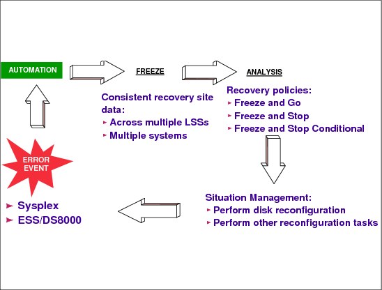
Figure 7-35 GDPS error recovery
GDPS error recovery
GDPS monitors many types of error events, the most significant category being changes in the remote copy configuration. This category is so important because this type of error may affect the time consistency of the recovery data. Figure 7-35 shows an example of the automatic procedure that a GDPS-based implementation could follow. The errors could be in Sysplex elements or in the remote copy activity.
When a volume is suspended because of a remote copy error condition, the automation routines immediately freeze the image of all the required secondary volumes, applying the CGROUP FREEZE command to all application-related LSSs that are known to GDPS. This preserves the consistency of the recovery data at that specified point in time. This action is followed by an analysis step. The analysis is driven by a predetermined policy, which can be either FREEZE and GO, or FREEZE and STOP, or FREEZE and STOP CONDITIONAL.
FREEZE and GO
With this option the automation routines allow applications to continue after the secondary volumes have been frozen. The implication is that updates to primary volumes after the freeze will be lost if a disaster occurs, and thus applications will have to be restarted in the recovery site. The other implication is that the availability of the application is favored, because it is not stopped by this error circumstance.
FREEZE and STOP
With this option the automation routines stop all applications right where they are at the time of freezing the secondary volumes. Application availability will be impacted, but the currency of the recovery site data is preserved.
FREEZE and STOP CONDITIONAL
With this option the automation routines freeze the image of the secondary volumes, and then analyze the reason for the suspend condition. If it turns out to be non-threatening, for instance, because a secondary piece of equipment has failed, then the applications are allowed to continue. However, if there is any indication of a serious problem, the automation routines then stop all the required applications.
7.35 GDPS/PPRC multi-site example
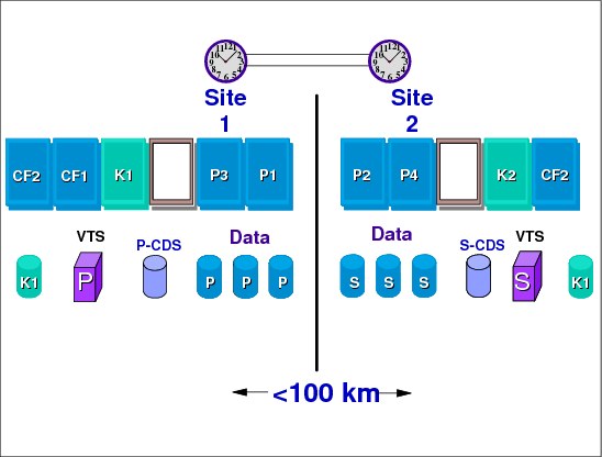
Figure 7-36 GDPS/PPRC multi-site example
GDPS/PPRC multi-site example
Figure 7-36 shows a GDPS/PPRC multi-site configuration. There is one Sysplex with production systems on both sites sharing data, for example a 50/50 distribution. There is a controlling system (K2) in Site 2. Both sites have the capability of increasing CPU resources through CBU to take over each other’s work, and DASD data and tape data are mirrored (primary and secondary site). HW and SW must be configured in terms of continuous availability, which includes data sharing across two sites and cloned applications and z/OS systems.
Other GDPS/PPRC configurations
This configuration is also called 100/0 distribution.
•GDPS/PPRC single-site
– One sysplex, all production systems in Site 1
– Controlling system in Site 2
– Expandable workload or CPU capacity backup (CBU) capable processors in Site 2
– Primary DASDs and tapes in Site 1, secondary DASDs and tapes in Site 2
– Site recovery by restarting failing system images in 2
GDPS/PPRC business recovery service (BRS) configuration
This is very similar to the single-site configuration, with the exception that Site 2 is owned by a third party and the controlling system will always be located in Site 1. Primary DASDs and tapes are located in Site 1and secondary DASDs and tapes in Site 2. K1 needs to be IPLed in Site 2 when Site 1 has a failure. This configuration can be used if:
•There is no second site but a disaster recovery (D/R) facility exists within maximum allowed PPRC distance.
•Dark fiber cannot be installed between company sites.
•You need to minimize cross-site link connectivity.
•An increased recovery time objective (RTO) is acceptable.
..................Content has been hidden....................
You can't read the all page of ebook, please click here login for view all page.