


Base and Parallel Sysplex
A sysplex has been available since 1990 when it was announced as a platform for an evolving large system computing environment. Sysplex provides a commercial platform that supports the nondisruptive addition of scalable processing capacity, in increments matching the growth of workload requirements for customers, without requiring re-engineering of customer applications or re-partitioning of databases. Sysplex also allows the computing environment to reach almost unimaginable levels of continuous availability or 24 by 7. Sysplex technology is built on existing data processing skills and runs existing applications with additional cost savings.
A sysplex (SYStems comPLEX) is not a single product that you install in your data center. A sysplex is a collection of z/OS systems that cooperate, using certain hardware, software, and microcode, to process workloads, provide higher continuous availability, easier systems management, and improved growth potential over a conventional computer system of comparable processing power. This chapter is an overview of a sysplex, including the following topics:
•Sysplex benefits, evolution, and philosophy
•Required software and hardware for sysplex
•Coupling facility
•The z/OS sysplex services components: XCF and XES
•Several types of couple data set (CDS)
•The sysplex configurations: base sysplex and Parallel Sysplex
•Sysplex exploiters
•Coupling facility structure rebuild and duplexing
•Coupling facility configuration and availability
•An overview of settings for sysplex
•Consoles and sysplex management
1.1 Evolution to a Parallel Sysplex

Figure 1-1 Evolution to a Parallel Sysplex
Evolution to a Parallel Sysplex
A Parallel Sysplex is the most recent development in the evolution of IBM large systems. Large system configurations have evolved from a single system to a Parallel Sysplex in the following progression:
•Single system uniprocessor
A single copy of the z/OS (or its ancestor) operating system manages the processing of a central processor complex (CPC) that has a single Central Processor (CP), also called a CPU.
•Tightly coupled multiprocessors
A single copy (also called an image) z/OS operating system manages more than one CP sharing the same central storage, thus allowing several transactions to have their programs executed in parallel.
•Loosely coupled configuration
This configuration is when more than one CPC, possibly tightly coupled multiprocessors, share DASD but not central storage. The CPCs are connected by channel-to-channel communications and are managed by more than one z/OS images.
•Base sysplex
A base sysplex is similar to loosely coupled but the z/OS system and applications programs use a standard communication mechanism for exchanging messages called XCF. This configuration makes the management easier because it provides a greater degree of communication and cooperation among systems and a more unified system image with a single z/OS console group to manage all components.
•Parallel Sysplex
A Parallel Sysplex has up to 32 z/OS systems, as in a base sysplex, but it contains a coupling facility (CF). The coupling facility is a global and intelligent memory that provides multisystem data sharing (with total integrity), workload balancing, high performance communication, and many other advantages.
Table 1 on page 3 summarizes the characteristics in terms of availability, capacity, and system management according to the system configuration.
Table 1 Evolution to a Parallel Sysplex
|
|
Capacity
|
Continuous availability
|
Systems management
|
|
Single system uniprocessor
|
Limited by the size of the largest single CP.
|
Single points of failure and disruptive changes.
|
Easy.
|
|
Tightly coupled multiprocessors
|
Limited by the maximum number of CPs in the CPC.
|
Single points of failure and disruptive changes.
|
Easy.
|
|
Loosely coupled configuration
|
Increased over tightly coupled.
|
Increased over tightly coupled.
|
Each system must be managed separately. Complexity grows with the number of systems.
|
|
Base sysplex
|
Same as loosely coupled.
|
Better than loosely coupled because of the cooperation.
|
Single z/OS console group to manage all components.
|
|
Parallel Sysplex
|
Ability to add incremental capacity to match workload growth.
|
Total (24 by 7), if there are not multiple concurrent failures.
|
Multisystem data- sharing capability, multisystem workload balancing, enhanced single-system image.
|
1.2 SYStems comPLEX or sysplex
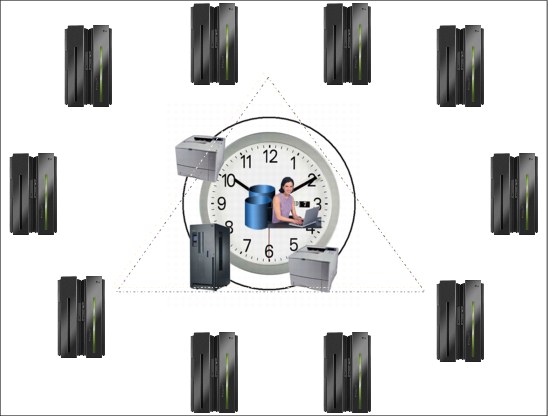
Figure 1-2 Systems complex or sysplex
SYStems comPLEX or sysplex
Parallel and clustered systems initially found in numerically intensive markets (engineering and scientific) have gained increasing acceptance in commercial segments as well. The architectural elements of these systems span a broad spectrum that includes massively parallel processors that focus on high performance for numerically intensive workloads, and cluster operating systems that deliver high system availability.
Parallel Sysplex clustering
Parallel Sysplex clustering contains innovative multisystem data-sharing technology, allowing direct concurrent read/write access to shared data from all processing images in a parallel configuration, without sacrificing performance or data integrity. Each image is able to concurrently cache shared data in a global electronic memory through hardware-assisted cluster-wide serialization and coherency controls. This in turn enables work requests associated with a single workload, such as business transactions or database queries, to be dynamically distributed for parallel execution on nodes in a sysplex cluster, based on available processor capacity. Through this state-of-the-art cluster technology, the power of multiple z/Series processors can be harnessed to work in concert on common workloads, taking the commercial strengths of the z/OS platform to improved levels of competitive price performance, scalable growth, and continuous availability. Prior to the Parallel Sysplex, S/390 (now called System z®) customers had been forced to contain capacity requirements of a workload within technology limits imposed by the largest single symmetric multiprocessor available (symmetric meaning all CPUs are the same).
1.3 The sysplex symmetry

Figure 1-3 The sysplex symmetry
The sysplex symmetry
You can think of a sysplex as a symphony orchestra. The orchestra consists of violins, flutes, oboes, and so on. Think of each instrument as representing a different product (or component) in the sysplex. The fact that you have several of each instrument corresponds to having several images of the same product in the sysplex.
Think of symmetry in the orchestra in the following ways:
•All the violins (or whatever instrument) sound basically the same, and play the same musical part.
•All the instruments in the orchestra share the same musical score. Each instrument plays the appropriate part for that instrument.
Similarly in the sysplex, you can make all the systems, or a subset of them, look alike (clone systems) and do the same work. All the systems can access the same database, and the same library of programs, each one using the information it needs at any point in time. The concept of symmetry allows new systems to be easily introduced, and permits automatic workload distribution all the time, even in the event of failure or when an individual system is scheduled for maintenance. Symmetry also significantly reduces the amount of work required by the systems programmer in setting up the environment.
In an asymmetric sysplex, each system has its own software and hardware configurations, so some of the system management benefits of being in a sysplex are lost.
1.4 Sysplex philosophy

Figure 1-4 Sysplex philosophy
Sysplex philosophy
A new violinist who joins the symphony orchestra receives a copy of the score, and begins playing with the other violinists. The new violinist has received a share of the workload. Similarly in a sysplex, if you add a system, the Customer Information Control System (CICS®) OLTP transaction workload can be automatically rebalanced so that the new system gets its share, provided you have set up the correct definitions in your sysplex.
Dynamic workload balancing
Theoretically, in the CICS OLTP environment, transactions coming into the sysplex for processing can be routed to any system. CICS uses the z/OS component called Workload Manager (WLM), along with CICSPlex® System Manager (CPSM), to dynamically route CICS transactions. For this to happen in the sysplex, you need symmetry; the systems across which you want to automatically balance the workload must have access to the same data, and have the same applications that are necessary to run the workload. In other words, no system affinity should be allowed.
Data sharing
We noted earlier that in the symphony orchestra, all the instruments share the same musical score, each playing the appropriate part. You can think of the musical score as a kind of database. Part of the definition of symmetry, as used in this book, is systems sharing the same resources. An important resource for systems to share is data and programs, either in the form of a database, or data sets. Symmetry through systems sharing the same database and program libraries facilitates dynamic workload balancing and availability. The coupling facility technology, together with the support in the database managers, provides the data sharing capability.
You improve application availability by using products that provide data sharing with the coupling facility technology, such as Information Management System Database Manager (IMS™ DB), DB2® Universal Data Base for z/OS (DB2), VSAM RLS, or Transactional VSAM Services (DFSMStvs).
Incremental growth
The conductor can add violins, or other instruments, to the orchestra one by one until the desired effect is achieved. The conductor would not want to hire five more violinists if only two are needed at the moment. A sysplex exhibits the same incremental growth ability. Rather than adding capacity in large chunks, most of which might remain idle, you can add small chunks closer to the size you need at the moment.
Also, the introduction of a new violinist is non disruptive. It is possible (although you might see this only in the most novel of musical pieces) that the violinist could walk onto the stage in the middle of the concert, take a seat, and begin playing with the others. There is no need to stop the concert. Similarly, with a sysplex, because of symmetry and dynamic workload balancing, you can add a system to your sysplex without having to bring down the entire sysplex, and without having to manually rebalance your CICS OLTP workload to include the new system.
Continuous availability
If a violinist gets sick and cannot be present for a given performance, there are enough other violinists so that the absence of one will probably not be noticeable. If a violinist decides to quit the orchestra for good, that violinist can be replaced with another. A sysplex exhibits similar availability characteristics. One of the primary goals of a sysplex is continuous availability. You can think of availability from these perspectives: the availability of your applications programs and the availability of your data.
With symmetry and dynamic workload balancing, your applications can remain continuously available across changes, and your sysplex remains resilient across failures. Adding a system, changing a system, or losing a system should have little or no impact on overall availability. With symmetry and data sharing, using the coupling facility, you also have enhanced database availability.
Automation plays a key role in availability. Typically, automation routines are responsible for bringing up applications, and if something goes wrong, automation handles the application’s restart. While automation does not play much of a role in our symphony orchestra, the need for automation is quite important in the sysplex, for availability as well as other reasons.
A facility of z/OS called Automatic Restart Manager (ARM) provides a fast restart and automatic capability for failed subsystems, components, and applications. ARM plays an important part in the availability of key z/OS components and subsystems by decreasing the mean-time-to-repair (MTTR), which in turn affects the availability of data.
For example, when a subsystem such as CICS, IMS DB, or DB2 fails, it might be holding resources, such as locks, that prevent other applications from accessing the data they need. ARM quickly restarts the failed subsystem; the subsystem can then resume processing and release the resources, making data available once again to other applications. Note that System Automation for z/OS (SA z/OS), an IBM product that provides automation of operator functions such as start-up, shutdown, and restart of subsystems, has awareness of z/OS Automatic Restart Manager, so that restart actions are properly coordinated. A sysplex is also the framework that provides a single system image.
1.5 Single system image
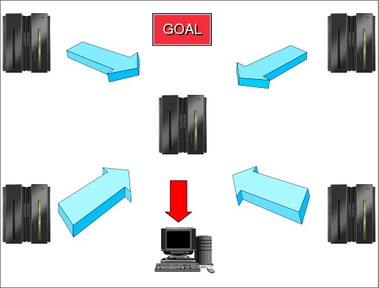
Figure 1-5 Single system image
Single system image
Think of all the violins in the symphony orchestra playing the same part. To the audience, they might sound like one giant violin. The entire orchestra is cooperating to produce the music that the audience hears. In this way, the audience perceives the orchestra as a single entity. This is a good way to picture single system image in the sysplex. You have multiple images of the same product, but they appear, and you interact with them, as one image. The entire sysplex is cooperating to process the workload. In this way, you can think of the collection of systems in the sysplex as a single entity.
Single system image is not a new concept. Many products already provide single system image capability to some degree, or have plans to implement it in the context of commercial enterprise-wide systems management. The important point is, single system image is a key theme in a sysplex. Implementing symmetry in your sysplex facilitates single system image; symmetry facilitates your ability to manage multiple systems in the sysplex as though they were one system. Now, you have the best of two worlds, a logical centralized topology implemented in a physically distributed one.
While single system image is the goal, different IBM and non-IBM products, and even different components within products, are at different stages of development on this issue. Attaining the goal depends on the installation choosing the right options on such products and components.
Different perspectives on single system image
The single system image goal provides different advantages depending on your perspective. The advantage for the end user is the ability to log onto an application in the sysplex, and to be able to access that application without being concerned about which system the application resides on.
For example, CICS uses the VTAM generic resources function, which allows an end user to log on to one of a set of CICS terminal-owning regions (TORs), such as TOR1, TOR2, and TOR3, through a generic name, such as TOR, thus providing single system image for VTAM access to CICS TORs. With dynamic workload management, provided by CICSPlex SM (a CICS component), the logons are then balanced across the CICS TORs; later, when the transactions start to arrive, they will be dynamically distributed through transaction application-owning regions (AORs) that are logically connected to the TOR at logon time. All of this provides a single system image from an application perspective.
The advantage to an operator is the ability to control the sysplex as though it is a single entity. For example, through commands with sysplex-wide scope, operators can control all the z/OS images in the sysplex as though only one z/OS image existed.
When TSO/E is part of a sysplex and exists on multiple sysplex members, you can assign a VTAM generic name to all TSO/E and VTAM application programs. A TSO/E and VTAM application on one z/OS system can be known by the same generic resource as a TSO/E and VTAM application on any other z/OS system. All application programs that share a particular generic name can be concurrently active. This means that a user can log on to a TSO/E generic name in the sysplex rather than to a particular system. The generic name can apply to all systems in the sysplex, or to a subset.
Eventually, when all the necessary products provides single system image capability, the result is greatly improved and simplified enterprise-wide systems management. Both IBM and non-IBM products work towards this goal.
Single point of control
The conductor of the symphony controls the entire orchestra from the podium. The conductor does not stand by the violins and conduct them for a while, and then run over and stand by the flutes to conduct them. In a sysplex, an operator or a systems programmer should be able to control a set of tasks for the sysplex from a given workstation.
The sysplex is a little different from the symphony orchestra in that single point of control in the sysplex does not imply a single universal workstation such as a console. The object is not to control every task for every person from one place. A given individual should be able to accomplish the set of tasks pertinent to that individual’s job from one place.
Ideally, you can have multiple consoles, each tailored to a particular set of tasks; for each such console, you can have either a duplicate of that console, or some other mechanism to ensure that for every task, there is an alternative way to accomplish the task in the event the console or its connection to the sysplex fails.
IBM and non-IBM products are furthering the ability to implement single point of control through integrating operations on a workstation. IBM provides an implementation of an integrated operations console through the Tivoli® Management Environment (TME) 10.
1.6 Parallel Sysplex workload balancing
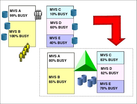
Figure 1-6 Parallel Sysplex workload balancing
Parallel Sysplex workload balancing
You might be wondering what a sysplex could do for you. If your data center is responsible for even one of the following types of work, you could benefit from a sysplex:
•Large business workloads that involve hundreds of end users, or deal with volumes of work that can be counted in millions of transactions per day.
•Work that consists of small work units, such as online transactions, or large work units that can be subdivided into smaller work units, such as queries.
•Concurrent applications on different systems that need to directly access and update a single database without jeopardizing data integrity and security.
Sharing the workload
A sysplex shares the processing of work across z/OS systems and as a result offers benefits such as reduced cost through more cost-effective processor technology using IBM software licensing charges in Parallel Sysplex.
Workload balancing
When you are in an environment with multiple systems, the set of performance issues changes. Existing mechanisms for managing system performance are complex and single-system oriented.
To reduce the complexity of managing a sysplex, MVS workload management provides dynamic sysplex-wide management of system resources. MVS workload management is the combined cooperation of various subsystems (such as CICS, IMS, and VTAM) with the MVS workload manager (WLM) component. An installation defines performance goals and a business importance to workloads through WLM. Workload management focuses on attaining these goals through dynamic resource distribution.
Workload management
A sysplex provides a different way of managing workloads than was previously used. The emphasis is on defining performance goals for work, and having MVS and the subsystems adapt to meet the goals. This provides for the following:
•A platform for continuous availability so that applications can be available 24 hours a day, 7 days a week, 365 days a year (or close to it).
•The ability to do more work to provide greater capacity and an improved ability to manage response time through the use of goals.
•Greater flexibility and the ability to mix levels of hardware and software.
•The ability to dynamically add systems, which allows an easy path for incremental growth.
•Considering resource sharing (of unit tapes, for example), resources are used in the system that needs them, instead of being dedicated. That enables better environment management, performance, and cost savings.
•Data sharing and resource sharing are the fundamental mechanisms that allow installations to have their workload dynamically redistributed between images in the Parallel Sysplex. Workload can be routed to systems where spare capacity exists, avoiding CEC upgrade and still meeting service level objectives, as shown in Figure 1-6.
For example, CICS is usually implementing the function shipping capability toward the file owner region (FOR) in order to share VSAM files across multiple CICS application regions. Most of the time this FOR region becomes a bottleneck and a single point of failure. In a Parallel Sysplex environment, with data sharing, transactions can be routed to a CICS address space with workload balancing and better response time in the Parallel Sysplex. This requires a transaction management tool, like CICSPlex SM, but the basic framework is the Parallel Sysplex.
Sysplex configurations
A sysplex configuration can be either a base sysplex or a Parallel Sysplex. Later in this chapter, after introducing all the hardware and software required in a sysplex, both configurations are described. The configurations are described in “Base sysplex” on page 51 and “Parallel Sysplex” on page 52.
1.7 Sysplex software

Figure 1-7 Sysplex software
Sysplex software
The following types of software exploit sysplex capabilities:
System System software is the base software that is enhanced to support a sysplex. It includes the z/OS operating system, JES2 and JES3, and DFSMS.
Networking Includes Virtual Telecommunications Access Method (VTAM) and Transmission Control Protocol/ Internet Protocol (TCP/IP), which support attachment of a sysplex to a network.
Data management Data management software includes data managers that support data sharing in a sysplex, such as Information Management System Database Manager (IMS DB), DATA BASE 2 (DB2), and Virtual Storage Access Method (VSAM). We can also include here Adabas and Oracle.
Transaction management Transaction management software includes transaction managers that support a sysplex such as Customer Information Control System (CICS Transaction Server), Information Management System Transaction Manager (IMS TM) and WebSphere Application Services.
Systems management Systems management software includes a number of software products that are enhanced to run in a sysplex and exploit its capabilities. The products manage accounting, workload, operations (as DFSMShsm), performance (as RMF), security (as RACF), and configuration (as HCD).
1.8 Sysplex hardware
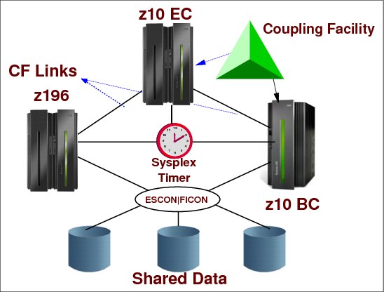
Figure 1-8 Sysplex hardware
Sysplex hardware
A sysplex is a collection of MVS systems that cooperate, using certain hardware and software products, to process work. A conventional large computer system also uses hardware and software products that cooperate to process work. A major difference between a sysplex and a conventional large computer system is the improved growth potential and level of availability in a sysplex. The sysplex increases the number of processing units and MVS operating systems that can cooperate, which in turn increases the amount of work that can be processed. To facilitate this cooperation, new products were created and old products were enhanced. The following types of hardware participate in a sysplex.
System z processors
Selected models of System z processors can take advantage of a sysplex. These include large water-cooled processors, air-cooled processors, and the processors that take advantage of (CMOS) technology.
Coupling facility
Coupling facilities enable high performance multisystem data sharing. Coupling facility links, called channels, provide high speed connectivity between the coupling facility and the central processor complexes that use it. These z/OS systems can be located in the same or in different CPCs that have the coupling facility.
Sysplex Timer
The Sysplex Timer® is an external time reference (ETR) device that synchronizes the time-of-day (TOD) clocks across multiple CPCs in a sysplex. The time stamp from the Sysplex Timer is a way to monitor and sequence events within the sysplex. Server Time Protocol (STP) is a server-wide facility providing capability for multiple z/OSs to maintain TOD time synchronization with each other and form a Coordinated Timing Network (CTN). It is a cost saving replacement for the Sysplex Timer.
FICON and ESCON
The term Fibre Connection (FICON®) represents the architecture as defined by the InterNational Committee of Information Technology Standards (INCITS), and published as ANSI standards. FICON also represents the names of the various System z server I/O features. ESCON® and FICON control units and I/O devices provide the increased connectivity necessary among a greater number of systems.
ESCON channels and directors, and FICON channels and directors (switches), are Enterprise Systems Connection (ESCON) and Fiber Connection (FICON) channels that enhance data access and communication in the sysplex. The ESCON directors and FICON switches add dynamic switching capability for those channels.
FICON is widely used in the System z environment, and provides additional strengths and capabilities compared to the ESCON technology. Many additional capabilities have been included in support of FICON since it was originally introduced. Some control units and control unit functions might require FICON use exclusively. For example, Hyper Parallel Access Volume requires the use of FICON and will not work with ESCON.
1.9 Sysplex Timer

Figure 1-9 Sysplex Timer
Sysplex Timer
Time is a key variable for commercial programs. In physics there are three time scales:
•Universal international time (UIT) based on the earth revolution cycles. Not used for modern purposes due to the variability of such cycles.
•International atomic time (TAI) based on the radioactive properties of Cesium 133.
•Coordinated universal time (UTC) is derived from TAI, but kept not far from UIT by adding or deleting discrete units of leap seconds.
Several System z processors can execute several task programs in a data processing complex. Each of these processors has a time-of-day (TOD) clock, which is an internal 104-bit register incremented by adding a one in bit position 51 every microsecond. TOD clocks use a UTC time scale.
Multiple TOD clocks
When tasks are shared among different CPUs, multiple TOD clocks can be involved. These clocks might be in sync with one another. All CPU TODs from the same CPC are internally synchronized. Then, there is a need for a single time resource, that is, an External Time Reference (ETR) to synchronize the TOD clocks of CPUs located in distinct CPCs running z/OS in the same sysplex. The Sysplex Timer is hardware that is used when the sysplex consists of z/OS systems running in more than one CPC.
|
Note: Currently, you have the possibility of replacing a Sysplex Timer by Server Time Protocol (STP), as shown in “Server Timer Protocol (STP)” on page 17. The Sysplex Timer provides synchronization for the TOD clocks of multiple CPUs in distinct CPCs, and thereby allows events started by different CPUs to be properly sequenced in time. For example, when multiple CPUs update the same database, all updates are required to be time stamped in proper sequence in the database log.
|
Timer functions
There is a long-standing requirement for accurate time and date information in data processing. As single operating systems have been replaced by multiple, coupled operating systems on multiple servers, this need has evolved into a requirement for both accurate and consistent clocks among these systems. Clocks are said to be consistent when the difference or offset between them is sufficiently small. An accurate clock is consistent with a standard time source.
The IBM z/Architecture, Server Time Protocol (STP), and External Time Reference (ETR) architecture facilitates the synchronization of server time-of-day clocks to ensure consistent time stamp data across multiple servers and operating systems. The STP or ETR architecture provides a means of synchronizing TOD clocks in different servers with a centralized time reference, which in turn might be set accurately on the basis of an international time standard (External Time Source). The architecture defines a time-signal protocol and a distribution network, which permits accurate setting, maintenance, and consistency of TOD clocks.
External time reference (ETR)
External time reference hardware facility (ETR) is the generic name for IBM Sysplex Timer. The ETR architecture provides a means of synchronizing TOD clocks in different CPCs with a centralized time reference, which in turn can be set accurately on the basis of UTC time standard (External Time Source). The architecture defines a time-signal protocol and a distribution network (called the ETR network) that permits accurate setting, maintenance, and consistency of TOD clocks.
Timing services
Timing services are implemented in z/OS by a time supervisor component. It can be used by an application program to obtain the present date and time, and convert date and time information to various formats. Interval timing lets your program set a time interval to be used in the program logic, specify how much time is left in the interval, or cancel the interval. For programs that are dependent upon synchronized TOD clocks in a multi CPC environment, like a database, it is important that the clocks are in ETR synchronization. These programs can use the STCKSYNC macro to obtain the TOD clock contents and determine if the clock is synchronized with an ETR. STCKSYNC also provides an optional parameter, ETRID, that returns the ID of the ETR source with which the TOD clock is currently synchronized.
ETR attachments
The ETR feature in System z9® and System z10® servers provides the interface to a Network Time Protocol (NTP) server with pulse per second (PPS) support.
|
Note: The zEnterprise 196 does not support the IBM Sysplex Timer and ETR attachment.
|
1.10 Server Timer Protocol (STP)

Figure 1-10 Server Time Protocol (STP)
Server Time Protocol (STP)
Server Time Protocol (STP) is designed to help multiple System z servers maintain time synchronization with each other, without the use of a Sysplex Timer. STP uses a message-based protocol in which timekeeping information is passed over externally defined coupling links, such as InterSystem Channel-3 (ISC-3) links configured in peer mode, Integrated Cluster Bus-3 (ICB-3) links, and Integrated Cluster Bus-4 (ICB-4) links. These can be the same links that already are being used in a Parallel Sysplex for coupling facility message communication.
STP is implemented in the Licensed Internal Code (LIC) of System z servers and CFs for presenting a single view of time to PR/SM™.
|
Note: A time synchronization mechanism, either IBM Sysplex Timer or Server Time Protocol (STP), is a mandatory hardware requirement for a Parallel Sysplex environment consisting of more than one server.
|
STP link
An STP link is a coupling facility connection that serves as a timing-only link. With STP links, you can allow multiple servers to form a Coordinated Timing Network (CTN), which is a collection of servers and coupling facilities that are synchronized to a time value called Coordinated Server Time. Establishing an STP link between two processors does not require a CF partition; an STP link can be established between two OS partitions. For an STP link, HCD generates a control unit of type “STP” on both sides of the connection. No devices are defined.
This server-wide facility provides capability for multiple z/OS systems to maintain TOD synchronization with each other and form a Coordinated Timing Network (CTN), that is, a collection of z/OS systems that are time synchronized to a time value. In Figure 1-10, the preferred time is as follows:
•P1 is the z/OS preferred timer server (stratum 1) that synchronizes the TODs of the z/OS systems (stratum 2).
•P2 is the backup time server, ready to replace P1.
•P3 is the arbiter time server that decides when the replacement should be done.
The External Time Reference connections are replaced by the implementation of STP, which makes use of coupling links to pass timing messages to the servers. Transition to STP makes it possible to have a Mixed Coordinated Network configuration. The Sysplex Timer provides the timekeeping information in a Mixed CTN. Once an STP-only configuration is established, the ETR connections are no longer needed. STP allows coexistence with Sysplex Timer in mixed configurations. The Sysplex Timer console is replaced by an HMC screen for each possible time zone.
|
Note: A z196 cannot be connected to a Sysplex Timer; consider migrating to an STP-only Coordinated Time Network (CTN) for existing environments. It is possible to have a z196 as a Stratum 2 or Stratum 3 server in a Mixed CTN, as long as there are at least two System z10 or System z9 servers attached to the Sysplex Timer operating as Stratum 1 servers.
|
Defining STP links in a sysplex
Server Time Protocol is designed to help multiple System z servers maintain time synchronization with each other, without the use of a Sysplex Timer. STP uses a message-based protocol in which timekeeping information is passed over externally defined coupling links, such as InterSystem Channel-3 (ISC-3) links configured in peer mode, Integrated Cluster Bus-3 (ICB-3) links, and Integrated Cluster Bus-4 (ICB-4) links. These can be the same links that already are being used in a Parallel Sysplex for coupling facility message communication.
An STP link is a coupling facility connection that serves as a timing-only link. With STP links, you can allow multiple servers to form a Coordinated Timing Network (CTN), which is a collection of servers and coupling facilities that are synchronized to a time value called Coordinated Server Time. Establishing an STP link between two processors does not require a CF partition; an STP link can be established between two OS partitions. For an STP link, HCD generates a control unit of type STP on each side of the connection. No devices are defined.
You can establish an STP link between two System z servers (z890, z990, z9 EC, or later). In the Connect to CF Channel Path dialog, select two CHPIDs defined for coupling facilities, and then specify the Timing-only link option to create an STP link.
1.11 Coupling facility
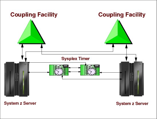
Figure 1-11 Coupling facility
Coupling facility
A coupling facility is a special logical partition that runs the coupling facility control code (CFCC) and provides high-speed caching, list processing, and locking functions in a sysplex. HCD enables you to specify whether a logical partition can be a coupling facility, operating system, or either on certain processors. You connect the coupling facility logical partition to a processor through the coupling facility channels.
With z/OS services, a component called XES allows authorized applications, such as subsystems and z/OS components, to use the coupling facility to cache data, exchange status, and access sysplex lock structures in order to implement high performance data sharing and rapid recovery from failures.
Coupling facility control code (CFCC)
IBM CFCC is licensed internal code (LIC) and always runs under an LPAR, regardless of whether the CF is in a standalone CPC or in a general purpose CPC (where CFCC LPs are together with z/OS LPs). A standalone CPC is a CPC only allowing LPs running CFCCs.
CFCC is a simple but efficient operating system where, for example, no virtual storage support is implemented. It has multiprocessing capabilities running multiple processors and when there is no work to do, it loops in the CF link waiting for work requests (the interrupt mechanism is not implemented).
A coupling facility (CF) runs the coupling facility control code (CFCC) that is loaded into main storage at power-on reset (POR) time. CFCC can run on a stand-alone CF server or in a logical partition.
Coupling facility logical partition (LP)
The coupling facility LP is defined through HCD and processor resource/systems manager (PR/SM) panels on the Hardware Management Console (HMC). Once you have defined an LP to be a coupling facility LP, only the CFCC can run in that LP. When you activate the coupling facility LP, the system automatically loads the CFCC from the laptop support element (SE) hard disk of the CPC. Its major functions are:
•Storage management
•Support for CF links
•Console services (HMC)
•Trace, logout, and recovery functions
•Provide support for the list, cache, and lock structures
1.12 Message time ordering

Figure 1-12 Message time ordering
Parallel Sysplex configurations
As server and coupling link technologies have improved over the years, the synchronization tolerance between operating system images in a Parallel Sysplex has become more rigorous. In order to ensure that any exchanges of time stamped information between operating system images in a Parallel Sysplex involving the CF observe the correct time ordering, time stamps are included in the message transfer protocol between the server operating system images and the CF. This is known as message time ordering.
Message time ordering
Figure 1-12 illustrates the components of a Parallel Sysplex as implemented within the zSeries architecture. Shown is an ICF connection between two z10 EC servers running in a sysplex, and there is a second integrated coupling facility defined within one of the z10s containing sysplex LPARs. Shown also is the connection required between the coupling facility defined on a z10 and the sysplex timer to support message time ordering. Message time ordering requires a CF connection to the Sysplex Timer.
Before listing the message time ordering facility rules, a short description of the message time ordering facility is included here. When the CF receives the message, it verifies that the message’s time stamp is less than the CF’s TOD clock. If the time stamp in the message is ahead of the CF’s TOD clock, the message is not processed until the CF TOD clock catches up to the message time stamp value.
Mixed or STP-only Parallel Sysplex
In a mixed or STP-only CTN in a Parallel Sysplex configuration, the requirement is that all servers support the message time ordering facility.
The following message time ordering facility rules are enforced when there is a mixed CTN in a Parallel Sysplex configuration:
•z/OS images running on STP-configured servers can connect to CFs that are on servers that are not STP capable only if the coupling facility supports message time ordering facility and is attached to the Sysplex Timer.
•CFs on an STP-configured server can connect to z/OS images running on servers that are not STP capable only if the non-STP-capable server supports message time ordering facility and is attached to the Sysplex Timer.
For more details about this topic, see the document Server Time Protocol Planning Guide, SG24-7280.
1.13 Coupling facility LPARs and CFCC code

Figure 1-13 Coupling facility LPARs and CFCC code
Standalone coupling facility (CF)
A standalone CF is a CPC where all the processor units (PUs), links, and memory are for CFCC use. This means that all LPs running in such a CPC run only CFCC code. The standalone CF is also called external coupling facility.
Internal coupling facility (ICF)
ICFs are PUs in a CPC configured to run only CFCC code. The PUs are not shipped with a fixed function assignment (personality), but are assigned during power-on reset (POR) or later non-disruptively by on demand offerings such as: CBU, CuOD, CIU, ON/OFF COD. Those offerings allow the customer to convert, in seconds, a non-characterizable PU in any PU personality type such as: CPU, ICF, IFL, zAAP, zIIP and SAP.
An ICF can reduce the cost of exploiting coupling facility technology because:
•ICFs are less expensive than CPs.
•An ICF has a special software license charge. Special PR/SM microcode prevents the defined ICF PUs from executing non-CFCC code such as z/OS.
Coupling facility configuration options
A coupling facility always runs CFCC code within a PR/SM LPAR license internal code (LIC). As we already saw, a CF LPAR can be configured in one of two ways:
•In a standalone CPC, only coupling facilities are present
•In a general purpose CPC, the CF LP can co-exist with LPs running z/OS code, or even Linux® (under z/VM® or not). The z/OS LPs can be either in the same Parallel Sysplex as the coupling facility or not.
Decisions regarding where to configure CF LPs are based mostly on price/performance, configuration characteristics, CF link options, and recovery characteristics (availability).
CF storage
CFCC formats central storage in contiguous pieces called structures. Structures can be used to keep data by software exploiters (authorized programs) such as: z/OS components, subsystems, products. The exploiters may have several instances running in different z/OS systems in the sysplex. The major reason for having structures is to implement data sharing (with total integrity), although the structures may be used as high-speed caching memory. Structure types are:
•Lock structure
•List structure
•Cache structure
Each structure type provides a specific function to the exploiter. Some storage in the coupling facility can also be allocated as a dedicated dump space for capturing structure information for diagnostic purposes. In order to access the coupling facility structures, z/OS systems (running the exploiters) must have connectivity to the coupling facility through coupling facility links. Refer to “Coupling facility links” on page 25 for more information.
Coupling facility control code level (CFLEVEL)
The level (CFLEVEL) of the coupling facility control code (CFCC) that is loaded into the coupling facility LPAR determines what functions are available for exploiting applications. Various levels provide new functions and enhancements that an application might require for its operation. As more functions are added to the CFCC, it might be necessary to allocate additional storage to a coupling facility structure. Similarly, as new functions are added, the coupling facility itself may require additional storage. In any configuration, the amount of fixed storage required for the coupling facility is based on configuration-dependent factors.
To implement a coupling facility in your sysplex requires both hardware and software, as follows:
•CPC that supports the CFCC.
•CPCs on which one or more z/OS images run and which are capable of connecting to the coupling facility with CF links.
•Appropriate level of z/OS that allows an exploiter to access a desired function when managing the coupling facility resources.
•CFCC must implement the functions the exploiter needs.
To support migration from one CFCC level to the next, you can run several levels of CFCC concurrently as long as the coupling facility logical partitions are running on different servers (CF logical partitions running on the same server share the same CFCC level).
1.14 Coupling facility links

Figure 1-14 Coupling facility links
Coupling facility links
To enable the communication between a coupling facility (CF) logical partition (LP) and the z/OS (LPs), special types of high-speed CF links are required. These links are important because of the impact of link performance on CF request response times. For configurations covering large distances, time spent on the link can be the largest part of CF response time.
The coupling link types for the coupling facility are:
(PSIFB, IC, ICB, and ISC-3)
A CF link adapter can be shared between LPs, meaning the same adapter can transfer data from/to different z/OS systems to one CF, thus reducing the number of links needed. This is called multiple image facility (MIF), the same name used for FICON and ESON channels.
CF links in the System z servers work in a mode called peer mode. In this mode we have even more flexibility with connections. For example, a single link adapter can be connected (multiple image facility) to both z/OS and a CF.
Both the coupling facility LPs and the CF links must be defined to the I/O configuration data set (IOCDS). Hardware configuration definition (HCD) provides the interface to accomplish these definitions and also automatically supplies the required channel control unit and I/O device definitions for the coupling facility channels.
Internal coupling (IC) link
The IC is a zSeries or z9 connectivity option that enables high-speed connection (more than 3 GB/sec) between a CF LP and one or more z/OS LPs running on the same zSeries or z9 CPC. The IC is a linkless connection (implemented in Licensed Internal Code) and so does not require any hardware or cabling.
InterSystem Channel (ISC) link
InterSystem Channel provides connectivity through optical cables. ISC links are point-to-point connections that require a unique channel definition at each end of the link. There are two types of ISC features supported, ISC-3 and ISC-2. In modern CPCs such as System z servers (z800, z900, z890, z990 and z9), there is support for ISC-3 only. They are used for distances beyond 7 meters and allow a rate of up to 200 MBps.
Integrated Cluster Bus (ICB)
Integrated Cluster Bus provides connectivity through copper cables. They are faster than ISC links, attaching directly to a Self-Timed Interconnect (STI) bus of the CEC cage. They are the preferred method for coupling connectivity when connecting System z servers over short distances (up to 7 meters). For longer distances, ISC-3 links must be used. There are two types of ICB links available:
•ICB-4 links provide 2 GB/sec coupling communication between z990, z890, and z9 CPCs.
•ICB-3 links provide 1 GB/sec coupling communication between z800, z900, z990, z890, and z9 CPCs.
InfiniBand coupling links (PSIFB)
InfiniBand coupling links (PSIFB) are high speed links on z196, z10, and z9 servers. The PSIFB coupling links originate from three types of fanout. PSIFB coupling links of either type are defined as CHPID type CIB in HCD/IOCP, as follows:
•HCA2-O (FC 0163)
The HCA2-O fanouts support InfiniBand Double Data Rate (IB-DDR) and InfiniBand Single Data Rate (IB-SDR) optical links. The HCA2-O fanout supports PSIFB coupling links at distances of up to 150 meters. PSIFB coupling links operate at 6 GBps (12x IB-DDR) when connecting a z196 or z10 to z196 and z10 servers, and at 3 GBps (12x IB-SDR) when connecting a z196 or z10 to a z9. The link speed is auto-negotiated to the highest common rate.
•HCA2-O LR (FC 0168)
The HCA2-O LR fanout supports PSIFB Long Reach (PSIFB LR) coupling links for distances of up to 10 km and up to 100 km when repeated through a DWDM. This fanout is supported on z196 and z10. PSIFB LR coupling links operate at up to 5.0 Gbps (1x IB-DDR) between z196 and z10 servers, or automatically scale down to 2.5 Gbps (1x IB-SDR) depending on the capability of the attached equipment.
•HCA1-O (FC 0167)
The HCA1-O fanout supports InfiniBand Single Data Rate (IB-SDR) optical links. The HCA1-O fanout supports PSIFB coupling links at distances of up to 150 meters. PSIFB coupling links operate at 3 GBps (12x IB-SDR) when connecting the z9 server to a z196 or z10 server.
Publications of interest
zSeries Connectivity Handbook, SG24-5444, Processor Resource/Systems Manager Planning Guide, SB10-7036, z/OS MVS Setting Up a Sysplex, SA22-7625, and HCD Planning, GA22-7525.
1.15 Sysplex overview

Figure 1-15 Sysplex overview
Sysplex overview
Now that the pieces that make up a sysplex have been introduced, the remainder of this chapter presents an overview of the sysplex. Figure 1-15 is an overview of the remaining topics to be discussed in this chapter.
It is difficult to explain the sysplex without first explaining the cross-system coupling facility (XCF) and its services, so we start by describing XCF, its services and exploiters. Take note that despite having in the name the expression “coupling facility,” XCF is not able to access such coupling facility directly.
Next, the sysplex configurations and how system consoles are used to enter sysplex-related commands are described, as follows:
•Fundamentals of a base sysplex (a function of XCF), what is required and how to define it.
•An overview of Parallel Sysplex and how to migrate from a base to a Parallel Sysplex.
•Which PARMLIB members you have to change in order to define a sysplex and which changes are necessary.
•How to use consoles in a sysplex environment; how many consoles you need and which ones are mandatory.
•The sysplex-related commands, how to direct a command to a specific console, and how to reply to messages.
1.16 Cross-system coupling facility (XCF)

Figure 1-16 Cross-system coupling facility (XCF)
Cross-system coupling facility (XCF)
The cross system coupling facility (XCF) component of z/OS provides simplified multisystem management. XCF services allow authorized programs on one system to communicate with programs on the same system or on other systems. If a system fails, XCF services also provide the capability for batch jobs and started tasks to be restarted on another eligible system in the sysplex.
XCF groups
An XCF group is a set of related members that a multisystem application defines to XCF. A member is a specific function, or instance, of the application. A member resides on one system and can communicate with other members of the same group across the sysplex.
Communication between group members on different systems occurs over the signaling paths that connect the systems; on the same system, communication between group members occurs through local signaling services. To prevent multisystem applications from interfering with one another, each XCF group name in the sysplex must be unique.
CICS address spaces
Each CICS address space in Figure 1-16 is an XCF instance. The terms instance, exploiting instance, or exploiter are used to denote the active subsystem or address space of a component, product, or function that directly exploits sysplex services. XCF is a z/OS component that provides services to allow multiple instances (named members) of an application or subsystem, running on different systems in a sysplex, to share status information and communicate through messages with each other. A set of same instance members is called a group. A member of an application can use XCF services to:
•Inform other members of their status (active, failed, and so forth).
•Obtain information about the status of other members, such as whether another member failed.
•Send messages to and receive messages from each other member, in the same or in another z/OS. The most frequent case is other z/OSs (inter-system communication).
Automatic Restart Manager (ARM)
If z/OS fails, XCF can call Automatic Restart Manager (ARM) services (a z/OS component) to provide the capability for batch jobs and started tasks to be restarted on another eligible z/OS in the sysplex. Then an application is allowed to:
•Request automatic restart in the event of application or system failure
•Wait for another job to restart before restarting
•Indicate its readiness to accept work
•Request that automatic restart no longer be performed
•Indicate that automatic restart should be performed only if the backup copy of the application data no longer exists
1.17 Base sysplex

Figure 1-17 Base sysplex
Base sysplex
A base sysplex configuration is a sysplex with no coupling facilities. The base sysplex can be composed of one or more z/OS systems that have an XCF sysplex name and in which the authorized programs (members) use XCF services. XCF services are available in both single and multisystem environments. A multisystem environment is defined as two or more z/OS systems residing on one or more CPCs’ logical partitions connected through CTCs.
A base sysplex is the first step to implementing a Parallel Sysplex. A Parallel Sysplex is a base sysplex plus the use of the coupling facility. So, when you introduce the coupling facility, XCF exploits the coupling facility, using it as a link between z/OS systems.
Figure 1-17 shows how XCF works in a multisystem sysplex. Each z/OS has an XCF component that handles groups for the participating members. Here you can see as an example the group named SYSGRS, which is very important for global resource serialization (in the group the name of each member is the name of the z/OS system). This group has one member (GRS component of z/OS) in each z/OS. Other groups can be: consoles (SYSMCS), JES2, JES3, WLM, and others. These groups are described in detail in 1.23, “XCF exploiters” on page 39.
The communication link between XCFs could be through channel-to-channel adapters (CTCs) that allow data movement between XCF buffers in the systems through an I/O operation. Another option for linking is a CF list structure, which is discussed later in this chapter.
1.18 XCF application, member, and group
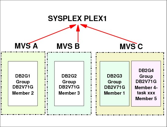
Figure 1-18 XCF application, member, and group
XCF application, member, and group
An application in a XCF context is a program that has various functions distributed across z/OS systems in a multisystem environment. An application or subsystem might consist of multiple instances, each running on a different system in the same sysplex. Typically, each instance performs certain functions for the application as a whole. Alternatively, each instance could perform all the application’s functions on a given system. XCF services is available to authorized applications, such as subsystems and z/OS components, to use sysplex services.
Member
A member is a specific function (one or more routines) of a multisystem application that is joined to XCF and assigned to a group by the multisystem application. A member concept applies to all authorized routines running in the address space that issued the IXCJOIN macro service. Only for termination purposes (resource clean-up), the member can be associated with an address space, job step, or task. XCF terminates the member when its association ends. The same address space can have more than one group.
Group
A group is the set of related members defined to XCF by a multisystem application in which members of the group can communicate with other members of the same group. A group can span one or more of the systems in a sysplex and represents a complete logical entity to XCF.
1.19 XCF services
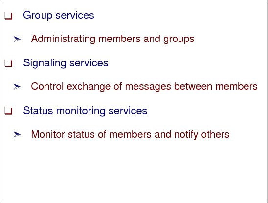
Figure 1-19 XCF services
XCF services
z/OS XCF allows up to 32 z/OS systems to communicate in a sysplex. XCF provides the services that allow multisystem application functions (programs) on one z/OS system to communicate (send and receive data) with functions on the same or other z/OS systems. The communication services are provided through authorized assembler macros and are as follows:
•Group services
•Signalling services
•Status monitoring services
Group services
XCF group services provide ways for defining members to XCF, establishing them as part of a group, and allowing them to find out about the other members in the group. A member introduces itself to XCF through the IXCJOIN macro. If a member identifies a group exit routine, XCF uses this routine to notify this member about status changes that occur to other members of the group, or systems in the sysplex; thus, members can have the most current information about the other members in their group without having to query each other.
Signaling services
The signaling services control the exchange of messages between members of an XCF group. The sender of a message requests services from XCF signaling services. XCF uses buffer pools to communicate between members in the same system, and it uses buffer pools plus signaling paths (CTCs or a CF list structure) to send messages between systems in the sysplex.
Status monitoring services
Status monitoring services provide a way for members to determine their own operational status and to notify the other members of the group when that operational status changes. An installation-written status exit routine identified to XCF determines whether a member is operating normally. An installation-written group exit routine identified to XCF allows a member to maintain current information about other members in the group, and systems in the sysplex.
1.20 XCF signaling paths
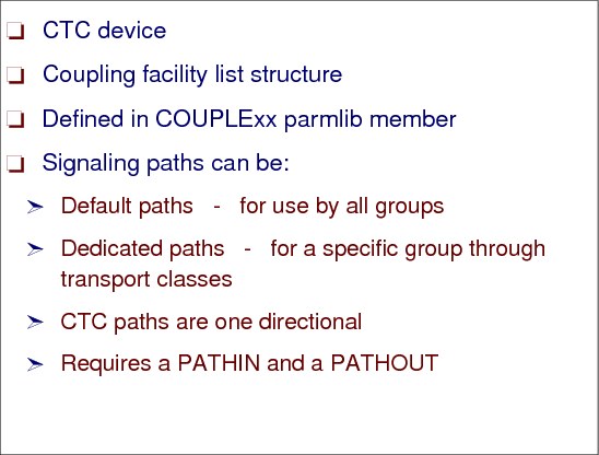
Figure 1-20 XCF signaling paths
XCF signaling paths
Whether you implement signaling through CTC connections or coupling facility list structures, you need to specify information in the COUPLExx parmlib member. After an IPL, you can issue the SETXCF START,PATHOUT or SETXCF START,PATHIN commands to specify outbound or inbound paths. To establish signaling through a coupling facility, you also need to define a coupling facility resource management (CFRM) policy.
Then, XCF group members use the signaling mechanism to communicate with each other. These communication paths can be:
•Channel-to-channel adapter (CTC) communication connections.
•Coupling facility through list structures. XCF calls XES services when the path of communication is a coupling facility.
•A combination of both, CTC and list structures. In this case XCF selects the faster path.
A message generated in a member has the following path:
•From the sending member to an XCF buffer in the output buffer pool.
•From the XCF output buffer through the signaling path:
– If a CTC goes directly to a buffer in the XCF input buffer pool.
– If CF list structure is stored for a while in the structure memory and from it to an XCF buffer in the input buffer pool. It is like a mail box.
•From the XCF input buffer to a receiving member.
The communication path is determined at IPL by the PATHIN and PATHOUT definitions in the COUPLExx PARMLIB member and can be modified by the SETXCF operator command. This is explained later in this chapter
CTC paths and devices
To establish signaling paths through CTC devices, you specify their device numbers in HCD. Each CTCA has a logical controller with a certain amount of logical devices. CTC devices are used by XCF in a uni-directional mode. That is, on each system, messages sent to other systems require an outbound path, and messages received from other systems require a separate inbound path. Then, for each z/OS in the sysplex, you must specify all devices for outbound paths and inbound paths on the DEVICE keyword of the PATHOUT and PATHIN statements in COUPLExx.
Coupling facility list structures
When you define signaling paths through coupling facility list structures, you define to z/OS which list structures to use and how to use them (as PATHIN or PATHOUT), and XCF (through z/OS) creates the logical connections between z/OSs that are using the structures for signaling.
Signaling paths and transport classes
Signaling path is the set of outbound paths plus outbound message buffers in one XCF. A transport class is a set of signalling paths that can be associated with XCF groups. Transport classes are defined in the COUPLExx member in PARMLIB. The reasons for associating an XCF group with a transport class include:
•To isolate the messages (signalling path wise) of these groups from the others
An example from COUPLExx is:
CLASSDEF CLASS(CICS) GROUP(DFHIR0000)
PATHOUT STRNAME(IXC_CICS) CLASS(CICS)
In this example, the group DFHIR0000 is associated with a transport class named CICS and all the messages out from the group use the CF list structure named IXC_CICS.
•To optimize the size of the message with the size of the output buffer
1.21 XCF channel-to-channel connection (CTC)

Figure 1-21 XCF channel-to-channel connection (CTC)
XCF channel-to-channel adapter connection (CTCA)
Full signaling connectivity is required between all z/OSs in a sysplex; that is, there must be an outbound and an inbound path between each pair of systems in the sysplex.
To avoid a single point of signaling connectivity failure, use redundant connections between each pair of systems, through either CTC connections or coupling facility list structures.
CTC signaling paths
CTC signaling paths are uni-directional and require at least four signaling paths between each z/OS (two inbound and two outbound paths). CTCA connections and their device numbers become more complex to manage as the number of z/OSs in the configuration increases. For example, it is almost impossible to have the same COUPLExx member for all the z/OSs in the sysplex. The formula producing the number of connections is: N x (N-1) where N is the number of z/OSs.
Coupling facility signaling paths are bi-directional; this offers better performance in general and is much less complex to maintain. We discuss coupling facility structures next.
1.22 XCF using coupling facility list structures
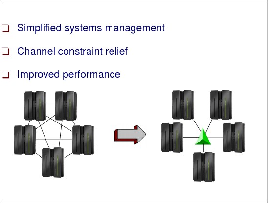
Figure 1-22 XCF using coupling facility list structures
List structures
A list structure consists of a set of lists and an optional lock table of exclusive locks, which you can use to serialize the use of lists, list entries, or other resources in the list structure. Each list is pointed to by a header and can contain a number of list entries. A list entry consists of list entry controls and can also include a data entry, an adjunct area, or both. Both data entries and adjunct areas are optional. However, data entries are optional for each list entry while a list structure either has or doesn’t have adjunct areas.
Simplified systems management
When XCF uses coupling facility structures for signaling, each other XCF in the sysplex can automatically discover its connectivity to other systems via the CF, without having to define point-to-point connections on every XCF in the configuration. Furthermore, in the event that a signaling path or signaling structure is lost, the recovery of CF signaling structures is automated and greatly simplified if more than one structure is allocated.
Channel constraint relief
XCF allows customers to consolidate CTC links used by VTAM, JES, and GRS into XCF communication, freeing up channel paths for other uses in constrained configurations. These advancements in CF coupling technologies combined with simplified systems management, ease of recovery, and better cost efficiencies, make XCF the clear choice for configuring XCF signaling paths in a Parallel Sysplex cluster.
List services (IXLLIST)
IXLLIST provides high-performance list transition monitoring that allows you to detect when a list changes from the empty state to the non-empty state (in which it has one or more entries) without having to access the coupling facility to check the list. For instance, if you are using the list structure as a distribution mechanism for work requests, list transition monitoring allows users to detect easily the presence or absence of incoming work requests on their queues.
1.23 XCF exploiters
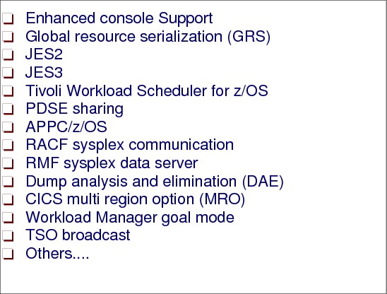
Figure 1-23 XCF exploiters
XCF exploiters
Figure 1-23 shows some sample z/OS components and products that exploit XCF services.
Enhanced console support
Multisystem console support allows consolidation of consoles across multiple z/OS images. A console address space of one z/OS image can communicate with console address spaces of all other images in the sysplex by means of XCF signaling. With this support, any console in the sysplex has the capability to view messages from any other system in the sysplex and to route commands in the same way.
Global resource serialization (GRS)
With the introduction of GRS Star, a new method of communicating GRS allocation requests was introduced. GRS Star uses a lock structure in the coupling facility as the hub of the GRS complex and eliminates the delays and processing overhead inherent in the traditional ring configuration. However, all quiescing and purging of images from GRS is done automatically by XCF. Also the execution of the GRSCAN function is done through XCF communication. This function is requested by performance monitors such as RMF in order to discover contention situations to be reported. To detect global contention the GRSs talk among themselves through XCF links.
JES2
When in multi-access spool (MAS) configuration (several JES2 member sharing the same spool data set), JES2 uses XCF to communicate with other members. Previously, all communication between members was via the JES2 checkpoint data set and, in the event of a system failure by one member of a JES2 MAS, the operator had to manually issue a reset command to requeue jobs that were in execution on the failing image and make them available for execution on the remaining images in the MAS complex. If running in a sysplex, this can be done automatically because of the XCF communication capability.
JES3
JES3 uses XCF services to communicate between JES3 systems in a complex. Previously, JES3 had to manage its own CTCs for this communication. This enables you to reduce the overall number of CTCs that need to be managed in your installation.
Tivoli Workload Scheduler for z/OS
IBM Tivoli Workload Scheduler for z/OS (TWS) is a subsystem that can automate, plan, and control the processing of a batch production workload. In a sysplex environment, TWS subsystems in separate z/OS images can take advantage of XCF services for communication with each other.
PDSE sharing
In partitioned data sets extended (PDSEs) access, XCF services is used for the exchange of locking information between the sharing systems in a sysplex (extended sharing only). Multiple images in a sysplex can concurrently access PDSE members for input and output, but not for update-in-place (the protection is implemented through XCF communication). That is, any member of a PDSE data set (pay attention that a PDSE member is not an XCF member), while being updated-in-place, can only be accessed by a single user. A sharer of a PDSE can read members, create new members or new copies of existing members concurrently with other sharers on the same or other images, input/output, but not for update-in-place.
APPC/z/OS
APPC/z/OS uses XCF to communicate with transaction-scheduler address spaces on the same image that APPC/z/OS is running on.
RACF sysplex communication
RACF can be enabled for sysplex communication between RACF members in the same sysplex. Doing this enables the subsequent commands to be propagated to RACF members in the sysplex other than the member who issued the command, thus simplifying multisystem security management.
RMF sysplex data server
The RMF data server is an in-storage area that RMF uses to store SMF data, which can then be moved around the sysplex to provide a sysplex-wide view of performance, via RMF Monitor III, without having to sign on to each of the systems individually.
Dump analysis and elimination (DAE)
Sharing the SYS1.DAE data set between images in a sysplex can avoid taking multiple dumps for the same problem if it is encountered on different systems in the sysplex.
CICS multi region option (MRO)
With CICS running in a sysplex, MRO has been extended to include cross-system MRO. This is achieved using XCF services for the cross-system communication, rather than having to use VTAM ISC links, as was previously required. This can give considerable performance benefits over current ISC implementations. MRO allows splitting of all the CICS functions that before were jammed in just one address space into several specialist address spaces, such as: terminal owning region or TOR (interface with VTAM to receive the incoming transaction), application owning region or AOR (where the programs containing the transaction logic are executed), file owning region (FOR) where VSAM data sets are accessed.
Workload manager in goal mode
WLM uses XCF for communication between WLM address spaces in the same sysplex. This communication is needed because the goals are global and not z/OS local.
TSO broadcast
If all z/OSs in the sysplex share the same SYS1.BRODCAST data set (used to send welcome messages to logged on users), and SYSPLXSHR(ON) is declared in IKJTSOxx PARMLIB member, then TSO NOTICEs are communicated via XCF signaling. Consequently, the I/O to the SYS1.BRODCAST data set is eliminated.
There are more XCF exploiters, such as DB2, IMS, DFSMS, VSAM, VTAM, and others.
1.24 Sympathy sickness

Figure 1-24 XCF Sympathy sickness
XCF sympathy sickness
There is one structural problem when messages from different XCF groups flow through common resources (message buffer pools and paths). This problem is not only with XCF, but is common with all message traffic.
The problem description is: If an input member fails (or slows down) in taking the messages out from the input buffer pool, this can hurt “innocent bystanders” in this and in other z/OS systems.
This can have the related effect of hurting users in other systems. It is known as “sympathy sickness.”
In the very busy Figure 1-24, if the application receiving messages (top right corner) is not taking its messages from the input buffer pool, this pool will be jammed, causing congestion in the normal flow. After a while, the application sending a message in another z/OS (bottom left corner) will receive back “MSG Rejected” because the output buffer pool is full. Depending on its logic this application may abend.
The objective of a new function, in z/OS 1.8 base and 1.6 with APAR OA09194, is to improve availability for innocent bystanders by automatically removing the stalled task that owns the messages that are filling the most PATHIN buffers. This function must be enabled through the SFM policy containing new MEMSTALLTIME parameter.
1.25 Sysplex couple data sets
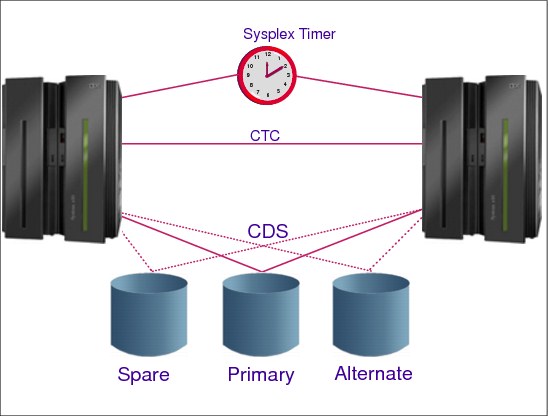
Figure 1-25 Sysplex couple data sets
Couple data sets
Figure 1.25 shows a sysplex of two z/OS systems, where both systems are connected to a Sysplex Timer and can access the sysplex couple data sets. The sysplex might also be configured so the systems can access one or more of the following couple data sets: ARM (automatic restart management), LOGR, SFM, WLM, z/OS UNIX, and a sysplex couple data set.
Sysplex couple data set
XCF requires a sysplex couple data set to be shared by all XCFs in the sysplex. The sysplex couple data set resides on a DASD device and is used to:
•Hold general status information about the z/OS images, XCF groups, and the XCF group members running in the sysplex
•Hold a description of pathouts and pathins together with buffer pools and transport classes
•Point to other couple data sets used in the sysplex
•Contain the heart beat data which inspects all systems to verify if they are alive and working
The couple data sets in a sense are used as a PARMLIB, that is, they have parameters set by the installation to customize the system. However, couple data sets are designed to be shared among z/OS systems in a sysplex (and are not actually a true PARMLIB). When a system programmer is creating their contents, care should be taken with the syntax of the statements.
All coupled data sets need to be created, formatted, and finally filled with installation options.
Primary and alternate data sets
To avoid a single point of failure, it is recommended to format a primary and an alternate couple data set on different devices, physical control units, and channels. All the updates in the primary are immediately copied in the secondary by XCF itself. If the primary data set fails, XCF switches automatically to the alternate data set. The alternate is now the primary couple data set. You can also perform a manual switch with the SETXCF COUPLE,PSWITCH command. Note that this command forces the alternate to be the primary, but the primary does not become the alternate, it is just deallocated. This allows you, for example, to:
•Increase the size of the primary couple data set
•Move the couple data set to a different device
•Change sysplex couple data set definitions
•Reformat the couple data set
Spare couple data set
It is recommended to pre-format a spare couple data set. With the SETXCF COUPLE,ACOUPLE command it is possible to define the spare data set as a new alternate couple data set, avoiding potentially having a single point of failure. The sysplex couple data sets (one type of couple data set) are defined to the XCFs in the sysplex with the PCOUPLE and ACOUPLE statements in the COUPLExx PARMLIB member.
Figure 1-30 on page 50 shows an example of formatting the sysplex couple data sets.
|
Tip: It is recommended that you place the primary sysplex couple data set on a different volume than the primary CFRM couple data set due to their high activities. You might allocate the primary sysplex couple data set together with the alternate CFRM couple data set on one volume, and vice versa.
|
1.26 Other couple data sets

Figure 1-26 Other couple data sets
Couple data sets policy
A policy is a set of rules and actions that z/OS systems in a sysplex follow when using certain z/OS services. A policy allows z/OS to manage specific resources in compliance with system and resource requirements but with little operator intervention. Depending on the policy type, you can set up a policy to govern all z/OS systems in the sysplex or only a set of selected z/OS systems. You might need to define more than one policy to allow for varying workloads, configurations, or other installation requirements at different times. For example, you might need to define one policy for your prime shift operations and another policy for other times. Although you can define more than one policy of each type (except for System Logger), but only one policy of each type can be active at a time.
The same primary and alternate CDS rules apply as described for the sysplex CDS. There are different CDS types (pointed to by the sysplex CDS) that hold the different policies.
Coupling facility resource management (CFRM) CDS
This CDS contains several CFRM policies. A CF structure is created by CFCC when the first exploiter connects to it (IXLCONN macro). Each structure has several attributes. Parallel Sysplex design requires that some of them should be informed by the exploiter software and others by the installation. The CFRM CDS contains a CFRM policy, that describes the structures attributes that should be decided by the installation. In the CFRM policy, you define:
•The coupling facility HW accessed by the sysplex. Major parameters are:
– CF name, sequence number, partition, cpcid, dumpspace
•All structures and their attributes, for example:
– Structure name, size, initsize
– The preferred CF name for the structure location
– CF duplexing, allowance of structure size altering and structure full monitoring function
Any structure used in the Parallel Sysplex must be defined in the CFRM policy.
Sysplex failure management (SFM) CDS
This CDS contains several SFM policies. SFM policy allows the installation to define responses to:
•Signaling connectivity failures among XCFs
•Signaling connectivity failures in CF links
•System failures, indicated by a status update (heart beat) missing condition
•Reconfiguring systems in a PR/SM environment
•Sympathy sickness
Workload Manager (WLM) CDS
This CDS contains several WLM policies. In the WLM policy you define workloads, service classes describing goals for workloads, application and schedule environments, goals for non-z/OS partitions and others related to system performance management.
Automatic Restart Manager (ARM) CDS
This CDS contains several ARM policies. In the ARM policy you define how to process restarts and other events for started tasks and batch jobs that failed but previously have registered with Automatic Restart Manager through macros.
One example is CICS and DB2 running dependent on each other. ARM handles this so-called restart group as defined in the ARM policy, through the policy options:
•Start the restart group only on the same system
•Which system in the sysplex should do the restart
•Number of restart attempts
•Restart order
|
Important: It is important to know that Automatic Restart Manager is not to be used as a replacement for system automation, but an addition to.
|
System Logger (LOGR) CDS
This CDS contains several LOGR policies. You use the LOGR policy to define, update, delete and manage log streams. A log stream is a sequential data set describing events, where the records are sorted by a time stamp. In a sysplex environment is almost mandatory to have just one CICS log (for example) instead of one log per each z/OS where CICS address spaces are running. The LOGR policy is used by System Logger services to manage log data across the z/OSs in the Parallel Sysplex. It guarantees the single image of a log merging in chronological order all the log records. Exploiters of System Logger services are: CICS, VSAM TVS, RRS, LOGREC, OPERLOG, and others.
UNIX System Services (OMVS) CDS
The OMVS CDS does not contain a policy. It’s used by XCF to maintain all the information to support UNIX System Services file system sharing across the sysplex. Recall that UNIX System Services is a z/OS component interfacing with a UNIX application running in z/OS.
1.27 Parallel Sysplex with couple data sets
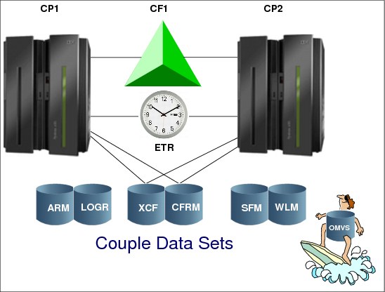
Figure 1-27 Parallel Sysplex and CDSes
Parallel Sysplex and CDSes
In order to full implement a Parallel Sysplex, you need to create and format the CDSes on DASD using the IXCL1DSU batch program utility. At least two of them are mandatory such as the sysplex CDS and CFRM CDS. See how to use the utility in “Format utility for couple data sets” on page 49.
Ensure that the CDSs are in DASD shared access by all sysplex members.
Defining an administrative policy
Once the CDSes for a service are formatted, you can define the administrative policies that reside on the data sets.
The CFRM, SFM, LOGR, and ARM administrative policies are defined, updated and deleted using the IXCMIAPU administrative data utility. IXCMIAPU is also used to provide reports describing the policies. Figure 1-28 on page 48 shows an example of how to use this utility.
The WLM policies are defined using the WLM ISPF (TSO) administrative application.
The sysplex CDS is created by using the COUPLExx PARMLIB member at IPL and can be altered later through the SETXCF console command.
Activating a policy
You activate a policy by issuing the following operator command:
SETXCF START,POLICY,TYPE=type,POLNAME=policy name
This causes the system to access the administrative policy from the type CDS. The new policy replaces the old policy definitions and will be used to manage the related resources.
|
//STOECKE JOB NOTIFY=&SYSUID,MSGLEVEL=(1,1),MSGCLASS=K,CLASS=A
//****************************************************************
//*
//* CFRM POLICY FOR PLEX1 CURRENT MEMBERS
//*
//* /SETXCF START,POL,TYPE=CFRM,POLNM=POLX <===
//*
//****************************************************************
//IXCCFRMP EXEC PGM=IXCMIAPU
//SYSPRINT DD SYSOUT=*
//SYSIN DD *
DATA TYPE(CFRM) REPORT(YES)
DEFINE POLICY NAME(POL5) REPLACE(YES)
CF NAME(CF1) TYPE(SIMDEV) MFG(IBM) PLANT(EN)
SEQUENCE(0000000CFCC1) PARTITION(0) CPCID(00)
DUMPSPACE(2000)
CF NAME(CF2) TYPE(SIMDEV) MFG(IBM) PLANT(EN)
SEQUENCE(000000CFCC2) PARTITION(0) CPCID(00)
DUMPSPACE(2000)
STRUCTURE NAME(IXCLST01) SIZE(40000) INITSIZE(4000)
PREFLIST(CF1,CF2) EXCLLIST(IXCLST02)
REBUILDPERCENT(1)
STRUCTURE NAME(IXCLST02) SIZE(40000) INITSIZE(4000)
PREFLIST(CF1,CF2) EXCLLIST(IXCLST01)
REBUILDPERCENT(1)
STRUCTURE NAME(ISGLOCK) SIZE(120000) INITSIZE(20000)
PREFLIST(CF1) REBUILDPERCENT(1)
STRUCTURE NAME(LOGREC) SIZE(128000) INITSIZE(32000)
PREFLIST(CF1,CF2) REBUILDPERCENT(1)
STRUCTURE NAME(OPERLOG) SIZE(128000) INITSIZE(32000)
PREFLIST(CF1,CF2) REBUILDPERCENT(1)
STRUCTURE NAME(IRLMLOCKTABL) SIZE(8192)
PREFLIST(CF1,CF2) REBUILDPERCENT(1)
.......
STRUCTURE NAME(DSNDB0M_GBP8K0) INITSIZE(3000)
SIZE(5000) PREFLIST(CF1,CF2)
DUPLEX(ENABLED)
STRUCTURE NAME(DSNDB0M_GBP16K0) INITSIZE(3000)
SIZE(5000) PREFLIST(CF1,CF2)
DUPLEX(ENABLED)
|
Figure 1-28 Example of a CFRM policy definition job
1.28 Format utility for couple data sets

Figure 1-29 Format utility for CDSs
Format utility for CDSs
The CDSs are created and formatted using the IXCL1DSU XCF format utility. You use the IXCL1DSU utility to format all types of CDSs for your sysplex.
This utility contains two levels of format control statements:
1. DEFINEDS - The primary format control statement identifies the CDS being formatted.
2. DATA TYPE - The secondary format control statement identifies the type of data to be supported in the CDS: sysplex, Automatic Restart Manager (ARM), CFRM, SFM, WLM, or LOGR data. In particular, note the recommendations about not over-specifying the size or the parameter value in a policy, which could cause degraded performance in a sysplex.
Formatting the sysplex CDS
Use the CDS format utility to create and format the sysplex CDSs prior to IPLing a system that is to use the sysplex CDSs. Other types of CDSs do not have to be formatted prior to IPLing the system.
Figure 1-30 shows the use of the format utility to format the sysplex CDSes. The values you specify in the MAXSYSTEM, GROUP and MEMBER keywords determine the CDS size.
|
//STEP1 EXEC PGM=IXCL1DSU
//STEPLIB DD DSN=SYS1.MIGLIB,DISP=SHR
//SYSPRINT DD SYSOUT=A
//SYSIN DD *
DEFINEDS SYSPLEX(PLEX1)
DSN(SYS1.XCF.CDS01) VOLSER(3380X1)
MAXSYSTEM(8)
CATALOG
DATA TYPE(SYSPLEX)
ITEM NAME(GROUP) NUMBER(50)
ITEM NAME(MEMBER) NUMBER(120)
ITEM NAME(GRS) NUMBER(1)
DEFINEDS SYSPLEX(PLEX1)
DSN(SYS1.XCF.CDS02) VOLSER(3380X2)
MAXSYSTEM(8)
CATALOG
DATA TYPE(SYSPLEX)
ITEM NAME(GROUP) NUMBER(50)
ITEM NAME(MEMBER) NUMBER(120)
ITEM NAME(GRS) NUMBER(1)
/*
|
Figure 1-30 Formatting the sysplex CDS
1.29 Base sysplex
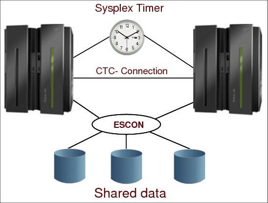
Figure 1-31 Base sysplex
Base sysplex
Recapping this concept, a base sysplex has:
•More than one z/OS image
•Shared DASD environment, meaning that the DASD volumes can be reached through channels by all the images
•XCF uses CTCA links and a sysplex CDS for communication with other XCFs in the sysplex
•External time synchronization between all z/OS images throughout a Sysplex Timer or a Server Time protocol (STP)
Simply stated, base sysplex is a step forward in a loosely coupled configuration.
Full signaling connectivity is required between all images in the sysplex. That is, there must be at least one inbound path (PATHIN) and one outbound path (PATHOUT) between each pair of images in the sysplex. XCF CTCA paths can be dynamically allocated and deallocated using the z/OS system command SETXCF START,PATHIN / PATHOUT. To avoid unplanned system outages due to signaling path failures, we recommend that you define multiple CTCA paths to XCF.
1.30 Parallel Sysplex
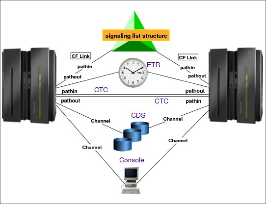
Figure 1-32 Parallel Sysplex
Parallel Sysplex
Parallel Sysplex architecture is generally characterized as a high performance shared data model. Each sysplex member has full read or write access control and globally managed cache coherency with high-performance and near-linear scalability. Specialized hardware and software cluster technology is introduced to address the fundamental performance obstacles that have traditionally plagued data-sharing parallel-processing systems.
Then recapping, Parallel Sysplex configuration has all the base sysplex components plus the coupling facility (CF). The core hardware technologies are embodied in the CF. The CF is used for data sharing together with the CF links, which enables the communication between the z/OS images and the CF. The same CF cannot be accessed by z/OS from different Parallel Sysplexes.
XCF signalling
The members of a sysplex use XCF signaling to communicate with each other.
•In a base sysplex this is done through CTCA connections.
•With Parallel Sysplex, signaling can be established through CF signaling list structures or CTCAs. A combination of both technologies is also possible.
Implementing XCF signaling through coupling facility list structures provides significant advantages in the areas of systems management, performance, recovery providing enhanced availability for sysplex systems. Signaling structures handle inbound and outbound traffic.
Signaling paths defined through CTCA connections must be exclusively defined as either inbound or outbound.
Because a single list structure can be defined for both inbound and outbound traffic, you can use the same COUPLExx PARMLIB member for each system in the sysplex. A CTCA connection, in contrast, cannot be defined to a single system as both inbound and outbound because the device numbers are different. Therefore, with CTCAs, you must specify a unique COUPLExx parmlib member for each system in the sysplex or configure your systems so that they can use the same COUPLExx member by over-specifying the number of devices for signaling paths and tolerating failure messages related to unavailable devices and other configuration errors.
Implementing XCF signaling through CF list structures also enhances the recovery capability of signaling paths and reduces the amount of operator intervention required to run the sysplex.
If XCF signaling is implemented through CF list structures, and if a CF that holds a list structure fails, or if connectivity to a CF that holds a list structure is lost, z/OS can rebuild the list structure in another available CF and reestablish signaling paths.
If the list structure itself fails, z/OS can rebuild it in the same CF or in another available CF and then reestablish signaling paths.
Parallel Sysplex support
The Parallel Sysplex supports up to 32 systems and significantly improves communication and data sharing among those systems. High performance communication and data sharing among a large number of z/OS systems could be technically difficult. But with Parallel Sysplex, high performance data sharing through a coupling technology gives high performance multisystem data sharing capability to authorized applications, such as z/OS subsystems.
Use of the CF by subsystems, such as CICS, IMS, DB2, VSAM, and others, ensures the integrity and consistency of data throughout the entire sysplex. The capability of linking many systems and providing multisystem data sharing makes the sysplex platform ideal for parallel processing, particularly for online transaction processing (OLTP) and decision support.
In short, a Parallel Sysplex builds on the base sysplex capability, and allows you to increase the number of CPCs and z/OS images that can directly share work. The CF enables high-performance, multisystem data sharing across all the systems. In addition, workloads can be dynamically balanced across systems with the help of workload management functions.
1.31 Cross-system extended services (XES)
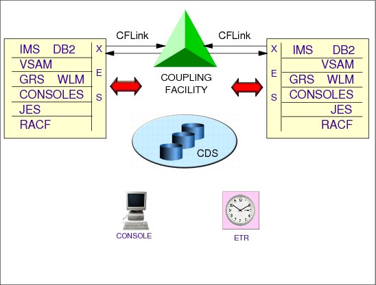
Figure 1-33 Cross-system extended services
Cross-system extended services (XES)
A coupling facility enables parallel processing and improved data sharing for authorized programs running in the sysplex. The cross-system extended services (XES) component of MVS enables applications and subsystems to take advantage of the coupling facility.
XES services
XES is a set of services that allows authorized applications or subsystems running in a sysplex to share data using a coupling facility.
XES allows authorized applications or subsystems running in z/OS systems in a Parallel Sysplex to use the CF structures.
XES provides the sysplex services (through the IXL... macros) that applications and subsystems use to share data held in the CF structures. XES may access one or more CFs in a Parallel Sysplex to:
•Provide high-performance data sharing across the systems in a sysplex
•Maintain the integrity and consistency of shared data
•Maintain the availability of a sysplex
To share data, systems must have connectivity to the CF through CF channels. Systems in the sysplex that are using a CF must also be able to access the coupling facility resource management (CFRM) CDS, where some structure attributes are described.
1.32 Sharing environments
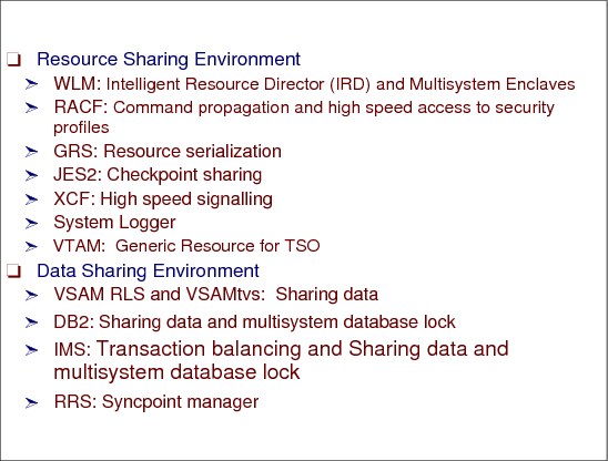
Figure 1-34 Sharing environments
Sharing environments
Parallel Sysplex exploitation can be classified according to how CF capabilities are used: to share system resources or to share data among transaction workloads.
Resource sharing environment
In a resource sharing environment, CF capabilities are not used for production data sharing such as IMS, DB2, or VSAM RLS. Some of the exploiters that use resource sharing to provide functions are:
•WLM: provides unique global performance goals and performance management at the sysplex level.
•RACF: Uses XCF for command propagation and CF for caching RACF data base in a store-through cache model. In the store- through cache model, all data updated (write) in the RACF buffer pool is staged to the CF cache structure and to DASD data set simultaneously. Eventually the next read will come from CF the cache structure. The use of Parallel Sysplex capabilities provides improved performance and scalability.
•JES2: JES2 uses the JES common coupling services (JES XCF) for communicating JES2 member status and other data among the JES2 XCF group members in a multi-access spool (MAS) configuration.
•XCF: Simplicity and even performance when using CF list structures for signaling.
•GRS star configuration: Uses CF structures for enqueues with overall better system performance and scalability compared to previous configuration (called ring).
•System Logger: There are two examples of exploiters using the System Logger for resource sharing. The first one is the operations log (OPERLOG) for console messages and commands, which records and merges messages about programs and system functions from each system in a sysplex. In Parallel Sysplex, OPERLOG can be used as a hardcopy medium instead of SYSLOG.
The second one is the LOGREC log stream to record hardware failures, selected software errors, and selected system conditions across the sysplex. Using a LOGREC log stream rather than a logrec data set (normally named SYS1.LOGREC) for each system can streamline logrec error recording.
•VTAM: Using TSO generic resource allows for increased availability and workload balancing because all TSO/VTAM application programs can be accessed by the same generic name. The CF structure is used to keep the generic name and the individual application name (Applid). Thus Workload Manager can be used to make efficient use of system resources by selecting a partner session based on balanced load distribution.
Data sharing environment
Data sharing is also known as application-enabled Parallel Sysplex environment and is one in which data management subsystems communicate with each other to share data with total integrity using CF capabilities.
In this environment IMS, DB2, or VSAM/RLS data sharing is implemented and full benefits of the Parallel Sysplex technology are afforded, providing capability for dynamic workload balancing across z/OSs with high performance, improved availability for both planned and unplanned outages, scalable workload growth both horizontally and vertically, etc.
In a data sharing environment, installations can take full advantage of the ability to view their multisystem environment as a single logical resource space able to dynamically assign physical system resources to meet workload goals across the Parallel Sysplex environment.
1.33 Coupling facility structures
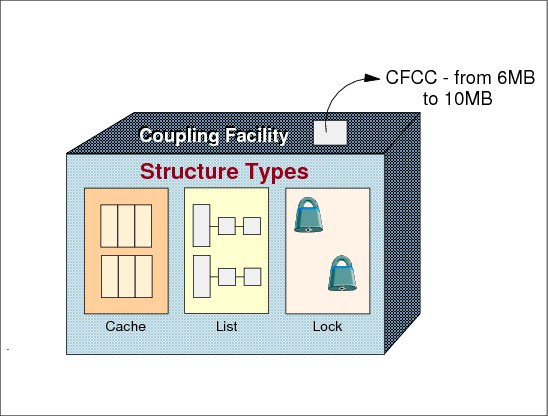
Figure 1-35 Coupling facility structures
Coupling facility structures
Within the CF, central storage is dynamically partitioned into structures. z/OS services (XES) manipulate data within the structures. There are three types of structures:
Cache structure
It has a directory and a data element area. Supplies a mechanism through the directory called buffer invalidation to ensure consistency of buffered data. Then, if the same DB2 page is duplicated in two DB2 local buffer pools, in two different z/OS and one copy is changed, then the other is invalidated because the information kept in the directory. The cache structure can also be used as a high-speed buffer (to avoid I/O operations) for storing shared data with common read/write access.
List structure
Enables authorized applications to share data that is organized in a set of lists, for implementing functions such as shared work queues and shared status information.
Lock structure
A lock structure supplies shared and exclusive locking capability for serialization of shared resources down to a very small unit of data (such as one lock per each DB2 page). Each lock manager control the locks related to the data that the transaction from its z/OS is accessing. One lock manager running in one z/OS can see the locks of other lock managers spread in the other z/OS systems. All the data in a data base is shared which allows updates from any data base manager.
Structure size
A CF structure is created when the first user (exploiter connection) requests connection to the structure. The size and the CF location for the structure allocation depends on:
•Values specified in the CFRM policy: Initial, maximum, smaller initial size, and minimum size.
•A minimum possible size as determined by the CFCC level.
A coupling facility is a special logical partition that runs the coupling facility control code (CFCC) and provides high-speed caching, list processing, and locking functions in a sysplex.
|
Note: You should be aware of your application’s CFLEVEL requirements. Different levels of coupling facility control code (CFCC) support different coupling facility functions.
|
•Structure size specified by the authorized application (exploiter) when using the XES services
•CF storage constraints
•CF storage increment
We highly recommend to use the CF Structure Sizer tool (CFSIZER) to plan your structure sizes. The sizing recommendations are always done for the highest available CFCC level. The CFSIZER is provided via the following:
1.34 DB2 cross invalidation (1)

Figure 1-36 DB2 Cross invalidation
DB2 cross invalidation
Let us follow an example on DB2 to see how the CF structures help in keeping data integrity. The scenario has DB2A and DB2B located in SYSA and SYSB, both in the same sysplex. There is a DB2 page with several valid copies: DASD, DB2A local buffer, DB2B local buffer, data element area in a CF cache structure. On the cache structure directory, the CFCC has also the information about the two copies in the local buffer pools.This information is passed to the CFCC by each DB2 when each copy of the page is loaded in the respective local buffer pool.
Now an end user (could be CICS) send a transaction to update that pages contents. To guarantee integrity of a lock (related to the page), an exclusive mode is requested and granted from the lock structure in the CF.
DB2 verifies if the page copy in the local buffer is still valid. All the copies are valid, so the update is done in that copy. This update creates a situation in which all the n-1 copies are invalid because they are not current. This lack of currency affects read integrity and needs to be overcome. To solve the problem, see “DB2 cross invalidation (2)” on page 60.
1.35 DB2 cross invalidation (2)

Figure 1-37 DB2 Cross invalidation
DB2 cross invalidation
DB2A informs the CFCC that the page contents was modified and also send a new copy to the data element area in the cache structure.
The CFCC by consulting the cache directory learns that DB2 has an valid copy of the page.
Then, asynchronously through the CF link, the CFCC turns on an invalid bit in a local cache vector area accessed by DB2B. There is a bit in every page in the DB2B local buffer pool. Obviously, the directory information about such a copy is erased.
Later, when DB2B needs a valid copy of the page, the testing (and consequent switch off) will tell DB2B that the copy is invalid. In this case, DB2B asks the CFCC for a valid copy that maybe is still in the data element area of the cache structure.
This algorithm is called cross invalidation and it guarantees the read integrity.
1.36 Level of Parallel Sysplex recovery

Figure 1-38 Evolution of parallel sysplex recovery
No recovery
Structures with no recovery mechanism contain typically either read-only or scratch-pad like data. A valid read-only copy is kept in DASD, for example. Recovery is not a major issue for these data types.
DASD backup
Some structures recover from hard failures by maintaining a hardened copy of the data on DASD. System Logger’s use of a staging data set is an example. The disadvantage is the synchronous write to DASD. The I/O operation is much slower in comparison to a CF structure update.
User-managed rebuild
User-managed rebuild was introduced along with initial CF support. It provides a robust failure recovery capability for CF structure data. z/OS XES coordinates a structure rebuild process with all active connectors to the structure. But it also requires significant amounts of supporting code from the exploiters to handle different complex recovery scenarios.
Structures duplexing
None of the above approaches are ideal. Several have significant performance overheads associated with them during mainline operation. One example is the cost of synchronously hardening data out to DASD in addition to the CF. Some of them compromise availability in a failure scenario by involving a potentially lengthy rebuild or log recovery process, during which the data is unavailable. The log merge and recovery for an non-duplexed DB2 group buffer pool cache is another example.
CF duplexing is designed to address these problems by creating a duplexed copy of the structure prior to any failure and maintaining that duplexed copy during normal use of the structure. This is done by transparently replicating all updates to the structure into both copies. The result is a robust failure recovery capability through failover to the unaffected structure instance. This results in:
•An easily exploited common framework for duplexing the structure data contained in any type of CF structure, with installation control over which structures are/are not duplexed.
•High availability in failure scenarios by providing a rapid failover to the unaffected structure instance of the duplexed pair with very little disruption to the ongoing execution of work by the exploiter and application.
Prior to duplexing, a structure could be recovered in one of these ways:
1. Copying the data from the existing structure instance to a new one. This is fast, but for large structures it can take more time. This option is available only for cache structures and link failure scenarios, not for CF failures. The source structure is lost in case of a CF failure.
2. Recreating the data from in-storage data in the connected systems. This option is slower than option number one.
3. Reading the required data from DASD. This option often involves restarting the affected subsystems and can be really slow.
4. Throw everything away and start with a new empty structure.
For duplexed structures, there is no recovery involved. The loss of a CF or connectivity to a CF no longer requires that the structure be rebuilt. Instead, the system automatically reverts back to simplex mode for the affected structure, dropping the affected copy of the structure in the process. So the recovery time is somewhere from a little faster to significantly faster.
User-managed duplexing
User-managed duplexing support was introduced in OS/390 R3. There are two structures (each one in each CF), the primary and the secondary. The exploiter is in charge of keeping both structures in synchronization and do the switch over to the failure-unaffected structure copy. Both instances of the structure are kept allocated indefinitely. This is only supported for cache structures. DB2’s group buffer pool cache structure technique is one of the exploiters.
System-managed rebuild
System-managed rebuild was introduced in OS/390 R8. This process allows to manage several aspects of the user-managed process that formerly required explicit support and participation from the connectors (exploiters). XES internally allocates the new structure and propagates the necessary structure data to the new structure. Then it switches over to using the new structure instance. XES is not capable of rebuilding the structure just by itself in failure scenarios but removes most of the difficult rebuild steps from user responsibility.
System-managed CF structure duplexing
In system-managed CF structure duplexing XES is much more involved than in user-managed duplexing, then relieving the exploiter code of a complex logic. However, because it is a generic implementation its performance is not so good as the previous one. IRLM, that is the DB2 lock manager is the main exploiter of such duplexing. For more details refer to the technical white paper: System-Managed CF Structure Duplexing, GM13-0103 available at:
1.37 User-managed rebuild
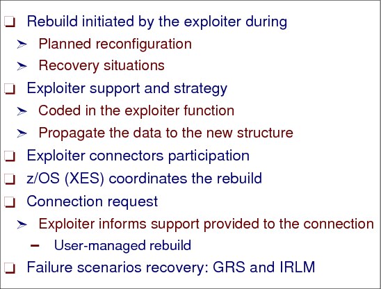
Figure 1-39 User-managed rebuild
User-managed rebuild
Most CF exploiters have implemented structure rebuild protocols to resume service promptly and subsequently allow the business to continue processing with minimal impact to service. User-managed rebuild is used in recovery situations and in planned structure reconfiguration. Because does not require "old" structure to still be available, so can recover from CF failure. In user-managed rebuild each CF exploiter implements its own rebuild strategy to suit its needs. The exploiter instances using structures rebuild their own structures. z/OS XES assists and coordinates the rebuild process and may in fact initiate the rebuild process. In a failure scenario, only the CF exploiter instances can determine whether rebuilding a structure is possible or not.Exploiter understands contents, so can optimize performance
Each set of same instance exploiters has its own rebuild strategy. Certain exploiters require all the data resident in the CF structure to be available to the surviving instances for a successful rebuild of the structure. This situation occurs when required information is spread among all the instances accessing the structure with no one instance having a complete view. The basic principle of these exploiters is: the loss of a single component is rare, the loss of two critical components is extremely rare. Thus these instances implement quick, automatic recovery following the failure of a single component; but accept longer and perhaps a more operator-intensive recovery should a double failure scenario occur.
A structure in other CF exploiters may have access to all the data required (if any) to handle the loss of a connected instance, the structure or an instance and the structure. Again, it depends on how the structure is used and the underlying assumptions each exploiter made with respect to the degree of loss and the probability of the loss.
Data sharing and resource sharing failure scenarios
Let us discuss an example of data sharing exploiter in three failure scenarios. IRLM is a component that provides locking services for DB2 and IMS; an IRLM instance is an address space in a z/OS system in which the IRLM code is running.
1. The failure of any one IRLM instance
All the remaining IRLM instances can obtain information from the IRLM lock structure, which allows them to continue granting DB2 or IMS locks while protecting the resources owned by the failed IRLM instance until such time as the recovery action against the failed IRLM instance is taken.
2. Loss of access to the IRLM lock structure
The active IRLM instances have enough information internally to rebuild and repopulate the IRLM lock structure. This recovery action is done without operator interaction and is completed in a matter of seconds. No one IRLM instance has enough information to rebuild the structure in this scenario. It takes a cooperative effort among all of the IRLMs to rebuild the structure.
3. Simultaneous loss of IRLM lock structure and the failure of an IRLM instance connected to the lock structure (the double failure scenario)
Rebuilding the structure is not possible. The surviving IRLM instances do not have sufficient information to rebuild the lock structure and protect the resources owned by the failed IRLM instances. The surviving IRLM instances abort the rebuild process and disconnect from the lock structure (in a failed persistent state). The database managers using the IRLM are unable to continue because locks cannot be granted or released. Recovery in this situation is neither automatic nor quick demanding data base forward recovery.
IRLM is failure-dependent and CF exploiters in such situations require a failure-independent environment. An example of an almost failure-independent environment is to avoid to locate the CF and the z/OS participating of the same Parallel Sysplex in the same CPC, to decrease the probability of a double failure. Another example could be duplexing the structure.
Now we show an example of a resource-sharing exploiter in the same failure scenarios.
GRS is a z/OS component that serializes access to resources through enqueue and reserve of z/OS services. We must recall that when a JOB ends abnormally (Abend) all the holding ENQs are automatically dequeued. When implemented in star configuration, GRS uses CF lock structures to hold sysplex-wide enqueues. Each GRS instance maintains only a local copy of its own global resources while the GRS CF lock structure has the overall image of all systems.
•In case of the failure of any number of z/OS images, enqueues held by the failed images are discarded by the GRS in the remaining systems.
•In case of loss of access to the GRS lock structure, the active GRS instances rebuild the lock structure into the alternate CF.
•In case of the simultaneous loss of the GRS lock structure and the failure of any system images, the surviving GRS images repopulate the alternate CF structure with enqueues they held at the time of failure.
GRS is a failure-independent CF exploiter and does not require a failure-independent environment. However, a failure-independent environment provides faster recovery. The two examples of the same rebuild strategy implementation with different effects on availability. IRLM needs a failure-independent environment because the data locked by the failed instance can compromise data integrity and availability. On the other hand, GRS does not require failure independence because the resources held by the failed system are released when the system dies.
1.38 User-managed duplexing
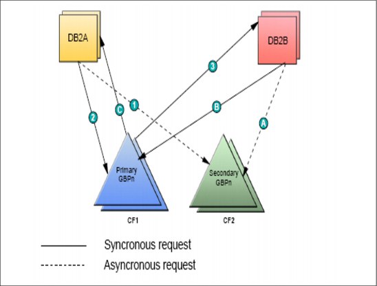
Figure 1-40 User-managed duplexing
User-managed duplexing
There are two types of rebuild processing, rebuild and duplexing rebuild. The method by which the rebuild processing is accomplished can be either user-managed or system-managed. User-managed duplexing rebuild, a variation of the structure rebuild process, is available only for cache structures. For duplexing to occur,all connectors to the structure must specify not only ALLOWDUPREBLD=YES but also ALLOWREBLD=YES when connecting to the structure.
Structure rebuild and duplexing rebuild provide the framework by which an application can ensure that there is a viable and accurate version of a structure being used by the application.
Structure rebuild allows you to reconstruct the data in a structure when necessary, for example, after a failure. Duplexing rebuild allows you to maintain the data in duplexed structures on an ongoing basis, so that in the event of a failure, the duplexed structure can be switched to easily. Duplexing rebuild is the solution for those applications that are unable or find it difficult to reconstruct their structure data after a failure occurs.
There are two structures (each one in each CF), the primary and the secondary. The exploiter is in charge of keeping both structures in synchronization and do the switch over to the failure-unaffected structure copy. Updates are propagated to both structures (the writes to the secondary are asynchronous) and reads are only from the primary. Both instances of the structure are kept allocated indefinitely. This is only supported for cache structures. DB2’s group buffer pool cache structure technique is one of the exploiters.
1.39 User-managed duplexing rebuild

Figure 1-41 User-managed duplexing rebuild
User-managed duplexing rebuild
User-managed duplexing rebuild was integrated into OS/390 V2R6 and is available only to CF cache structures. User-managed duplexing rebuild allows you to allocate another cache structure in a different CF for the purpose of duplexing the data in the structure to achieve better availability and usability. Although called a rebuild process, it is in fact a data duplication process or data synchronization between the two structures. So, in case of failure, the structure in an alternate CF is used.
The CF exploiter must support user-managed duplexing rebuild, since the exploiter is responsible for managing both instances of the structure and, when necessary, can revert to using only one of the structures. The connectors (exploiters) to the structure must participate in the defined protocol to accomplish the type of procedure—rebuild or duplexing rebuild. The connector is responsible for construction of the new instance and maintaining the duplicate data for a duplexed structure.
Simplex/duplex modes
In addition to the types of duplexing methods provided, a coupling facility structures can also be duplexed automatically. System-managed duplexing rebuild provides the capabilities of keeping two instances of a coupling facility structure, one a duplicate of the other. When there are two duplicate structure instances, the structure is considered to be in duplex-mode. If there is only one structure instance, the structure is considered to be in simplex-mode.
Installation decision
User-managed rebuild requires complex programming on the part of the product that uses the CF structure. The entire rebuild process has to be managed by the product. This includes tasks such as:
•Coordinating activity between all the connectors to stop any access to the structure until the rebuild is complete
•Working with other connectors of the structure to decide who rebuilds which parts of the structure content
•Recovering from unexpected events during the rebuild process
•Handling any errors that may arise during the process
DB2 group buffer pools
At this time, CF structure duplexing rebuild is supported by DB2 for its group buffer pools (GBP) cache structures. GBP is used for cross invalidation and as a cache for DB2 pages (to avoid DASD I/Os). DB2 writes to a primary GBP, it simultaneously writes to the secondary, duplexed GBP. Registering interest and reads are only done to the primary structure. Since both GBP instances are kept in sync with each other in terms of changed data, there are no concerns about the loss of the primary GBP because the data is still available in the alternate CF.
1.40 System-managed rebuild

Figure 1-42 System-managed rebuild
System-managed rebuild
System-managed duplexing rebuild is a process managed by the system that allows a structure to be maintained as a duplexed pair. The process is controlled by CFRM policy definition as well as by the subsystem or exploiter owning the structure. The process can be initiated by operator command (SETXCF), programming interface (IXLREBLD), or be MVS-initiated. Note that user-managed duplexing rebuild is controlled and initiated in the same manner as system-managed duplexing rebuild but is managed by the subsystem or exploiter owning the structure and applies only to cache structures.
System-managed rebuild is intended for use in planned reconfiguration scenarios and provides structure rebuild with minimal participation from structure connectors (exploiters).
System-managed rebuild provides the protocols to coordinate rebuild processing and provides the support necessary for rebuild. It does not require any active exploiter instance connected to the CF structure being rebuilt. The system-managed method requires that connectors recognize that the structure will become temporarily unavailable for requests, but does not require them to develop protocols to coordinate rebuild.
In the connection request, the exploiter states whether that connection supports system-managed processes or not. The first request to a structure determines the processes supported by all the connections to that structure.
System-managed rebuild cannot be used in a failure scenario because the primary structure must be available.
1.41 System-managed CF duplexing
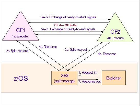
Figure 1-43 System managed duplexing
System-managed duplexing
The following requirements must be considered before system-managed duplexing rebuild can be established in a Parallel Sysplex environment. Figure 1-43 on page 69 shows the additional CF processing involved with system-managed duplexing.
1. XES receives an exploiter request in.
2. XES sends the request out to CF1 and CF2.
3. CF1 and CF2 exchange signals ready-to-start. At CFLEVEL 15 this exchange is dropped in normal situations to improve the performance.
4. Both CFs execute the write request.
5. When finished, the CFs exchange signals ready-to-end.
6. Each CF sends the response to XES.
7. When XES receives the reply from CF1 and CF2 the response out is returned to the exploiter.
The decision to enable a particular structure for system-managed duplexing is done at the installation level, through the DUPLEX keyword in the CFRM policy.
System-managed duplexing benefits
System-managed duplexing rebuild provides:
•Availability
Since the data is already in the second CF, a faster recovery is achieved. Any application that provides support for system-managed processes can participate in either system-managed rebuild or system-managed duplexing rebuild.
•Manageability and usability are provided by a consistent procedure to set up and manage structure recovery across multiple exploiters, it can significantly improve operability, resulting in improved availability.
•Enablement makes structures that do not have rebuild capability, like CICS temp storage and MQSeries®, viable in a high-availability environment.
•Reliability is a common framework that makes possible less effort on behalf of the exploiters, resulting in more reliable subsystem code.
•Cost benefits enables the use of non-standalone CFs
System-managed duplexing costs on resources
The system-managed duplexing costs depend on which structures are being duplexed and how they are being invoked by the applications. The structure updates impact:
•z/OS CPU utilization - Processing relating to send and receive two CF messages and response (instead of one).
•Coupling facility CPU utilization - The CF containing the structure now has to process requests that update the duplexed structure. The impact of processing these requests may have already been planned for to handle a CF rebuild situation in a simplex environment. Additional CF usage for both CFs is incurred to handle the CF-to-CF communication to coordinate the updates.
•Coupling facility link usage - Additional traffic on the links due to the additional requests to the secondary structure.
•The CF-to-CF links.
•z/OS CF link subchannel utilization - Will increase since the z/OS-to-CF response times increase due to the CF-to-CF communication.
•CF storage requirements need not increase. Although a new structure is now required on the second CF, this space should have already been planned for to handle the CF rebuild situation.
Costs versus availability installation decision
Even in a hardware and software configuration that fully supports system-managed duplexing rebuild, you must consider, on a structure by structure basis, whether the availability benefits to be gained from system-managed duplexing rebuild for a given structure outweigh the additional costs associated with system-managed duplexing for that structure. The availability benefits depend on considerations such as:
•Whether or not the structure exploiter currently supports rebuild
•Whether that rebuild process works in all failure scenarios
•How long that rebuild process generally takes, among others, compared to the rapid failure recovery capability that duplexing provides
The cost benefits depend on considerations such as:
•The hardware configuration cost - Possible additional CF processor and CF link capacity requirements
•Software configuration cost - Possible upgrades to installed software levels
•The coupling efficiency cost of duplexing the structure given its expected duplexing workload
1.42 CF structure rebuild
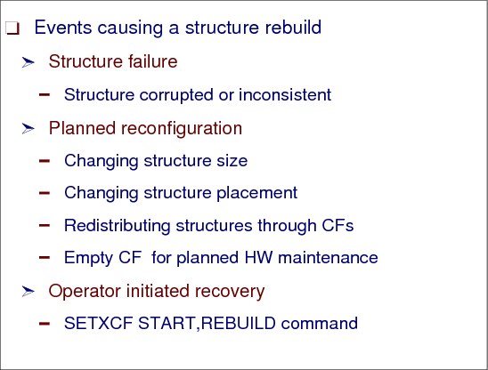
Figure 1-44 CF structure rebuild
CF structure rebuild
Here we are recapping the CF structure rebuild function. The reasons for rebuilding can be:
•Structure failures caused by a corruption or inconsistency
•Planned structure reconfiguration as structure size changes. Moving the structure to another CF for load balancing or to empty a CF for HW maintenance.
•Operator-initiated rebuild with SETXCF command:
SETXCF START,REBUILD,STRNAME=strname
You can use this command to recover a hung structure connector, for instance.
It’s important to know that a structure can only be rebuilt if there is an active structure connection and if the structure exploiter allows the rebuild.
The key to high availability in a Parallel Sysplex environment is the ability to quickly and without operator intervention recover from the failure of a single component. Rebuild is a process that involves the construction of a new instance of the CF structure. There are detailed structure rebuild and recovery scenarios in z/OS MVS Setting Up a Sysplex, SA22-7625.
A structure is allocated after the first exploiter connection request. The connection request parameter controls whether the connector supports structure alter (change the size dynamically), user-managed processes, or system-managed processes.
1.43 Parallel Sysplex availability

Figure 1-45 Parallel Sysplex availability
Parallel Sysplex availability
To get the availability benefits enabled by a Parallel Sysplex you must make the effort to exploit the capabilities it provides. In general it is possible to size a Parallel Sysplex to any of the availability levels required:
•High availability (HA) - no unplanned disruptions in the service caused by errors
– Delivers an acceptable or agreed service during scheduled periods.
•Continuous operation (CO) - planned outages do not disrupt the service
– These outages sometimes are needed to maintain the software and hardware. The redundancy caused by data sharing should not disrupt the service, but may affect performance due to less available capacity.
•Continuous availability (CA) - the 24 hours by seven days in the week (24 by 7).
– CA combines HA and CO techniques.
– We may say that 24 by 7 is the goal for installations exploiting all the Parallel Sysplex features and recommendations. The problem here is the occurrence of multiple concurrent failures, as in a disaster situation. Parallel Sysplex is not ready (and nobody else is) for concurrent multiple failures. In certain cases the 24 by 7 still can be delivered for double failures, but no more.
Continuous availability is a balance between costs and benefits. The fundamentals that contribute to achieving your availability goals are the following:
•Quality of technology
– Reliable components
– Redundancy in systems and network
– Capacity to support failures
– Exploitation of product availability features
– Resiliency and fast initialization
– Isolation of function
– Controlled diversity
– Security controls
– Automation
– End-to-end monitoring tools
•Robust applications and data
– Applications designed for high availability
– Redundant data and applications
– Minimal defects and fast recovery
•Skilled people
– Competence and experience
– Awareness and forethought
– Adequate depth of resources
– Proactive focus
– Management support
•Effective processes
– Service level objectives aligned with business
– High availability strategy and architecture
– Predefined recovery and incident procedures
– Robust testing
– Documented configuration and procedures
– Effective incident management
– Proactive problem prevention
– Minimal risk associated with change
For more detailed information, refer to: Achieving the Highest Levels of Parallel Sysplex Availability, SG24-6061and to the following website for availability information:
1.44 CF configuration examples
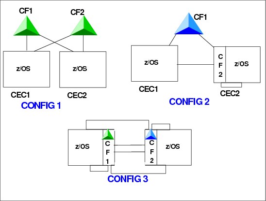
Figure 1-46 CF configuration samples
CF configuration samples
The CF is one component of a highly available Parallel Sysplex. To get high availability for a CF, you must eliminate single points of failure by designing the Parallel Sysplex based on the following factors:
•Number of CF LPs
•Number of ICF processors
•Placement of the CF LPs
– Standalone or not
– CF structure duplexing
•CF link technology, number of links and links shared or not
•Placement of CF structures
The robustness of the CF configuration depends on:
•The application or subsystem (exploiters) that utilizes the CF structures
•The location of the structure
•The capability of the CF exploiter of reacting to a double failure recovery scenario, that is, the simultaneous loss of a structure and a coupling exploiter connected to the structure
Applications using CF services may require different failure isolation techniques. Application-enabled environments (the ones exploiting data sharing) have more severe availability characteristics than resource sharing environments. Data sharing configurations exploit the CF cache and lock structures in ways that involve sophisticated recovery mechanisms, and some CF structures require failure independence to minimize recovery times and outage impact.
Configuring the Parallel Sysplex environment for high availability is closely tied to isolating the CF from the LPs on which software exploiters are executing (also isolating CFs from one another) to remove single points of failure.
CF LP on standalone CPCs
The standalone CF provides the most robust CF capability, because the CPC is wholly dedicated to running the CFCC code, that is, all of the processors (PUs), CF links, and memory are for CF use only. The various standalone CF models provide for maximum Parallel Sysplex connectivity. The maximum number of configurable PUs and memory is tied to the physical limitations of the associated machine family (that is, z900 Model 100 9-way, or z990 with 32 CPs).
Additionally, given the physical separation on the CF from production workloads, CFs can be independently upgraded and maintenance applied with minimal planning and no impact to production workloads. Also, a total failure in the standalone CPC causes just a single failure, because just one CF is down.
When choosing such a configuration, each CF LP from the same Parallel Sysplex must run in a different CPC, as shown in CONFIG1 in Figure 1-46 on page 74. That configuration is the most robust and also the most expensive. It is recommended for data sharing production environments without system-managed duplexing.
CF LP on a CPC running z/OSs of the same sysplex
A CF LP running on a CPC having a z/OS image in the same Parallel Sysplex introduces a potential for a single point of failure in a data sharing environment. This single point of failure is eliminated when using duplexing for those structures demanding a failure-independent environment.
When you choose a configuration such as CONFIG3 in Figure 1-46, and are not using system-managed duplexing, and you have an exploiter requiring that its structure be placed in a failure-independent environment, you must ensure that the CF is not in the same configuration as the z/OS systems that access it. For example, placing the CF in a CPC with one or more additional LPs that are running z/OS to access the CF would not provide a failure-independent environment.
Additionally, in this configuration, when the general purpose CPC is disruptively upgraded, any ICF processor in that CPC is also upgraded with no additional fee, while for a standalone CF additional expenses are needed for upgrade. On the other hand, this upgrade causes a CF outage and a z/OS outage at the same time.
Mixed configuration
A balance of availability and performance can be obtained by configuring a single standalone CF containing structures that require failure isolation, with an ICF that contains structures not requiring failure isolation, such as CONFIG2 in Figure 1-46. CF structure duplexing can then be enabled for those structures where the benefit outweighs the cost. This can typically be for those structures that have no fast method of recovery such as CICS Temporary Storage and others.
1.45 Parallel Sysplex exploiters
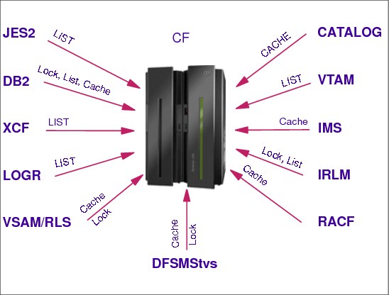
Figure 1-47 Parallel Sysplex exploiters
Parallel Sysplex exploiters
Authorized applications, such as subsystems and z/OS components in the sysplex, can use the CF services to cache data, share queues and status, and access sysplex lock structures in order to implement high-performance data-sharing and rapid recovery from failures. The subsystems and components transparently provide the data sharing and recovery benefits to their customer applications.
Some IBM data management systems that use the CF include database managers and a data access method, as follows:
•Information Management System Database Manager (IMS DB) is the IBM strategic hierarchical database manager. It is used for numerous applications that depend on its high performance, availability, and reliability. A hierarchical database has data organized in the form of a hierarchy (pyramid). Data at each level of the hierarchy is related to, and in some way dependent upon, data at the higher level of the hierarchy.
IMS database managers on different z/OS systems can access data at the same time. By using the CF in a sysplex, IMS DB can efficiently provide data sharing for more than two z/OS systems and thereby extends the benefits of IMS DB data sharing. IMS DB uses the CF to centrally keep track of when shared data is changed. IRLM is still used to manage data locking, but does not notify synchronously each IMS DB of every change. IMS DB does not need to know about changed data until it is ready to use that data.
•DATABASE 2 (DB2) is the IBM strategic relational database manager. A relational database has the data organized in tables with rows and columns.
DB2 data-sharing support allows multiple DB2 subsystems within a sysplex to concurrently access and update shared databases. DB2 data sharing uses the CF to efficiently lock, to ensure consistency, and to buffer shared data. Similar to IMS, DB2 serializes data access across the sysplex through locking. DB2 uses CF cache structures to manage the consistency of the shared data when located in local buffers. DB2 cache structures are also used to buffer shared data within a sysplex for improved sysplex performance.
•Virtual Storage Access Method (VSAM), a component of DFSMSdfp, is an access method rather than a database manager. It is an access method that gives CICS and other application programs access to data stored in VSAM data sets.
VSAM supports an data set accessing mode called record-level sharing (RLS). RLS uses the CF to provide sysplex-wide data sharing for CICS and the other applications that use the accessing mode. By controlling access to data at the record level, VSAM enables CICS application programs running in different CICS address spaces, called CICS regions, and in different z/OS images, to share VSAM data with complete integrity. The CF provides the high performance data-sharing capability necessary to handle the requests from multiple CICS regions.
•DFSMStvs, a transactional VSAM access method, provides a level of data sharing with built-in transactional recovery for VSAM recoverable files that is comparable to the data sharing and transactional recovery support provided by DB2 and IMS databases. In other words, DFSMStvs provides a log. The objective of DFSMStvs is to provide transactional recovery directly within VSAM. It builds on the locking, data caching and buffer coherency functions provided by VSAM RLS, using the CF hardware to provide a shared data storage hierarchy for VSAM data. It adds the logging and two-phase commit and back out protocols required for full transactional recovery capability and sharing.
•Enhanced catalog sharing (ECS). Catalog sharing requires that all changes to the catalog be communicated to all z/OSs to ensure data integrity and data accessibility. To maintain the integrity of the catalog, each system uses a combination of device locking and multiple I/Os to access a “shared record” in DASD for each of the catalogs. ECS enhances catalog sharing in a Parallel Sysplex cluster through the use of the CF. ECS provides a new catalog sharing method that moves the contents of the “shared record” to a cache structure in the CF. This allows z/OS images to access this information at CF speeds, eliminating most of the GRS and I/O activity required to access shared catalogs.
In addition to data management systems, there are other exploiters of the CF, such as Resource Access Control Facility (RACF) or the Security Server element of z/OS, and JES2. Transaction management systems (as CICS or IMS/DC) also exploit the CF to enhance parallelism.
1.46 Defining the sysplex
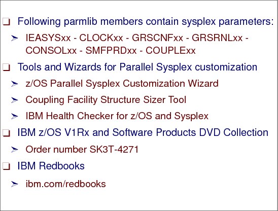
Figure 1-48 Defining the sysplex
Defining the sysplex
The following SYS1.PARMLIB members contain sysplex parameters. Most of them are discussed in the subsequent chapters.
•IEASYSxx
•CLOCKxx
•GRSCNFxx
•GRSRNLxx
•CONSOLxx
•SMFPRDxx
•COUPLExx
Tools and wizards for Parallel Sysplex customization
There are several tools, wizards, and tech papers linked from the IBM Parallel Sysplex URL:
•z/OS Parallel Sysplex Customization Wizard
•Coupling Facility Structure Sizer Tool
•IBM Health Checker for z/OS and sysplex
1.47 IEASYSxx PARMLIB definitions for sysplex

Figure 1-49 IEASYSxx PARMLIB definitions for sysplex
IEASYSxx PARMLIB definitions for sysplex
The values you specify in the SYS1.PARMLIB data set largely control the characteristics of z/OS systems in a sysplex. Many of the values that represent the fundamental decisions you make about the systems in your sysplex are in SYS1.PARMLIB.
IEASYSxx is the system parameter list that holds values that will be active in the z/OS just after the initialization (IPL) of z/OS. However, all those parameters may dynamically altered along the running of the system. Also in IEASYSxx you point to other PARMLIB members and those you need to consider, when setting up a z/OS system to run in a sysplex, are shown in Figure 1-49 and are discussed in the following pages.
SYSNAME parameter
You can specify the z/OS system name on the SYSNAME parameter in the IEASYSxx PARMLIB member. That name can be overridden by a SYSNAME value specified either in the IEASYMxx PARMLIB member or in response to the IEA101A Specify System Parameters message at console during IPL process.
You can specify system symbols in almost all parameter values in IEASYSxx. Symbols are variables that depending on the z/OS system may assume certain values. These symbols allow a same SYS1.PARMLIB be shared between several z/OSs. The IEASYMxx PARMLIB member provides a single place to define system symbols for all z/OSs in a sysplex.
1.48 IEASYSxx PLEXCFG parameter

Figure 1-50 IEASYSxx PLEXCFG parameter
IEASYSxx PLEXCFG parameter
The PLEXCFG IEASYSxx parmlib member parameter restricts the type of sysplex configuration into which the system is allowed to IPL. The option for a Parallel Sysplex is:
MULTISYSTEM PLEXCFG=MULTISYSTEM indicates that this IPLing z/OS is a part of a sysplex consisting of one or more z/OS systems that reside on one or more CPCs. The sysplex couple data set (CDS) must be shared by all systems.
You must specify a COUPLExx parmlib member that identifies the same sysplex couple data sets for all systems in the sysplex (on the COUPLE statement) and signaling paths, if applicable, between systems (on the PATHIN and PATHOUT statements). You must also specify in the CLOCKxx parmlib member whether you are using a Sysplex Timer that is real (ETRMODE=YES) or simulated (SIMETRID specification).
Use MULTISYSTEM when you plan to IPL two or more MVS systems into a multisystem sysplex and exploit full XCF coupling services. GRS=NONE is not valid with PLEXCFG=MULTISYSTEM.
The options available are as follows:
PLEXCFG={XCFLOCAL }
{MONOPLEX }
{MULTISYSTEM}
{ANY }
1.49 IEASYSxx GRS parameter

Figure 1-51 IEASYSxx GRS parameter
IEASYSxx GRS parameter
The GRS IEASYSxx parmlib member parameter indicates whether the IPLing z/OS is to join a global ENQ resource serialization complex.
In a multisystem sysplex, every system in the sysplex must be in the same global resource serialization (GRS) complex. This allows global serialization of resources in the sysplex. To initialize each z/OS system in the multisystem sysplex, you must use the GRS component of z/OS.
GRS options
Every z/OS a sysplex is a member of the same GRS complex. GRS is required in a sysplex because components and products that use sysplex services need to access a sysplex-wide serialization mechanism. You can set up either of the following types of complex for global resource serialization:
•GRS=STAR
In a GRS star complex, all of the z/OS systems (GRS) must be in the same Parallel Sysplex and connected to a CF lock structure in a star configuration via CF links.
Star is the recommended configuration.
If PLEXCFG=MULTISYSTEM the system starts or joins an existing sysplex and a global resource serialization star complex. XCF coupling services are used in the sysplex and in the complex.
•GRSRNLxx
This parameter specifies the suffix of the resource name lists (located in SYS1.PARMLIB) to be used to control the scope of the ENQ serialization of resources in the sysplex. This list describes if an ENW has a global or a local scope.
Use GRSRNL=EXCLUDE that indicates that all global enqueues are to be treated as local enqueues and you plan to use one software product to implement the ENW serialization.
All the other options of the GRS parameter are out of date and because of that, they are not described here.
1.50 CLOCKxx parmlib member
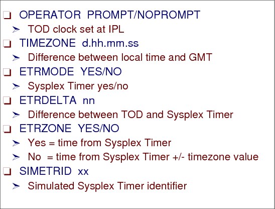
Figure 1-52 CLOCKxx parmlib member
CLOCKxx parmlib member
The CLOCK=xx parameter in the IEASYSxx PARMLIB member specifies the suffix of the CLOCKxx PARMLIB member used during system IPL. CLOCKxx indicates how the time-of-day (TOD) is to be set on the IPLing z/OS. TOD synchronizations is a must because as it operates, z/OS obtains time stamps from the TOD clock and uses these time stamps to:
•Identify the sequence of events in the system
•Determine the duration of an activity
•Record the time on online reports or printed output
•Record the time in online logs used for recovery purposes
There are two techniques to guarantee this TOD sync. One through Sysplex Timer and other through Server Time Protocol.
The CLOCKxx defines which technique is used and also informs things like Daylight Saving and TIMEZONE, that is the deviation from Greewhich.
Using CLOCKxx parmlib member
CLOCKKxx performs the following functions:
•Prompts the operator to initialize the time of day (TOD) clock during system initialization.
•Specifies the difference between the local time and Coordinated Universal Time (UTC).
•Controls the utilization of the IBM Sysplex Timer (9037), which is an external time reference (ETR). Having all systems in your complex attached and synchronized to a Sysplex Timer ensures accurate sequencing and serialization of events.
•Provides the means of specifying that the Server time Protocol (STP)
•architecture is to be used in the sysplex. STP defines the method by
•which multiple servers maintain time synchronization.
The CLOCKxx member for a system that is a member of a multisystem sysplex must contain a specification of ETRMODE YES, STPMODE YES, or both. The system then uses the Sysplex Timer or STP to synchronize itself with the other members of the sysplex. The system uses a synchronized time stamp to provide appropriate sequencing and serialization of events within the sysplex.
|
Note: If all MVS images in the sysplex will run in LPARs or under VM on a single physical processor, you can specify SIMETRID instead of ETRMODE YES or STPMODE YES.
|
For more information about CLOCKxx and the Sysplex Timer, see z/OS MVS Setting Up a Sysplex, SA22-7625.
1.51 COUPLExx PARMLIB member
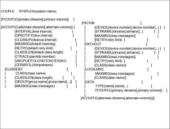
Figure 1-53 COUPLExx PARMLIB member
COUPLExx PARMLIB member
The COUPLE=xx parameter in the IEASYSxx PARMLIB member specifies the COUPLExx PARMLIB member to be used. It has options to be activated after the z/OS IPL related to XCF. Just browsing the COUPLExx keywords:
SYSPLEX SYSPLEX contains the name of the sysplex. The sysplex name allows a system to become part of the named sysplex. Specify the same sysplex-name for each z/OS system in the sysplex. Sysplex-name must match the sysplex name specified on the CDSs when they were formatted. The sysplex name is also the substitution text for the &SYSPLEX system symbol.
PCOUPLE PCOUPLE contains the names of the primary and sysplex CDSs.
ACOUPLE ACOUPLE contains the names of the alternate sysplex CDSs.
INTERVAL INTERVAL can contain values that reflect recovery-related decisions for the sysplex. INTERVAL specifies the failure detection interval at which XCF on another system is to initiate system failure processing for this system because XCF on this system has not updated its status within the specified time.
OPNOTIFY OPNOTIFY can contain values that reflect recovery-related decisions for the sysplex. OPNOTIFY specifies the amount of elapsed time at which XCF on another system is to notify the operator that this system has not updated its status (heart beat). This value must be greater than or equal to the value specified on the INTERVAL keyword.
CLEANUP CLEANUP can contain values that reflect recovery-related decisions for the sysplex. CLEANUP specifies how many seconds the system waits between notifying members that this system is terminating and loading a non-restartable wait state. This is the amount of time members of the sysplex have to perform cleanup processing.
PATHIN/PATHOUT
PATHIN and PATHOUT describe the XCF signaling paths for inbound/outbound message traffic. More than one PATHIN/PATHOUT statement can be specified. The PATHIN/PATHOUT statement is not required for a single-system sysplex.
PATHIN and PATHOUT describe the XCF signaling paths for inbound/outbound message traffic. More than one PATHIN/PATHOUT statement can be specified. The PATHIN/PATHOUT statement is not required for a single-system sysplex.
– DEVICE specifies the device number(s) of a signaling path used to receive/send messages sent from another system in the sysplex.
– STRNAME specifies the name of one or more CF list structures that are to be used to establish XCF signaling paths.
Note: Either the STRNAME keyword or the DEVICE keyword is required.
|
COUPLE SYSPLEX(&SYSPLEX.)
PCOUPLE(SYS1.XCF.CDS02)
ACOUPLE(SYS1.XCF.CDS03)
INTERVAL(85)
OPNOTIFY(95)
CLEANUP(30)
/* MAXMSG(500) */
RETRY(10)
/* CLASSLEN(1024) */
/* DEFINITIONS FOR CFRM POLICY */
DATA TYPE(CFRM)
PCOUPLE(SYS1.XCF.CFRM04)
ACOUPLE(SYS1.XCF.CFRM05)
........
/* LOCAL XCF MESSAGE TRAFFIC */
LOCALMSG MAXMSG(512) CLASS(DEFAULT)
PATHIN DEVICE(4EE0,4F00,4F10,4F20)
PATHOUT DEVICE(5EE0,5F00,5F10,5F20)
PATHOUT STRNAME(IXC_DEFAULT_1,IXC_DEFAULT_2)
PATHIN STRNAME(IXC_DEFAULT_1,IXC_DEFAULT_2)
CLASSDEF CLASS(BIG) CLASSLEN(62464) MAXMSG(4096) GROUP(UNDESIG)
PATHIN STRNAME(IXC_DEFAULT_3)
PATHOUT STRNAME(IXC_DEFAULT_3) CLASS(BIG) MAXMSG(4096)
PATHIN DEVICE(4EE9,4F09,4F19,4F29)
PATHOUT DEVICE(5EE9,5F09,5F19,5F29) CLASS(BIG) MAXMSG(4096)
........
|
Figure 1-54 COUPLExx member sample
1.52 Consoles in a sysplex
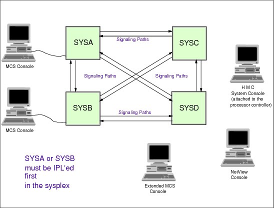
Figure 1-55 Consoles in a sysplex
Consoles in a sysplex
Traditionally, operators on a z/OS image receive messages from programs and enter commands to programs through consoles. These programs can be a z/OS component, or a subsystem or a customer application. Some of the messages imply that the operator should enter a reply. The traffic of messages and commands is managed by multisystem console support (MCS), a z/OS component. With MCS, a sysplex comprised of many z/OS images can be operated from a single console, giving the operator a single point of control for all images (as a cockpit in an airplane). To get more os consoles concepts, please refer to chapter 5 in this volume. In a sysplex, MCS consoles can:
•Be physically attached to any system, but just one at time
•Receive messages from any system in the sysplex, the messages are sent from one z/OS to other z/OS through XCF services.
•Route commands to be executed in any system in the sysplex, the commands are sent from one z/OS to other z/OS through XCF services.
Therefore, the following considerations apply when defining MCS consoles in this environment:
•There is no requirement that each system have consoles physically attached
•A sysplex, which can be up to 32 systems, can be operated from a single console (not recommended)
•One of the consoles must have master command authority, to issue any command
•All the commands before being executed are granted access (or not) by RACF or any other product in charge of the system security.
There are four types of operator consoles in a sysplex: MCS consoles, SMCS consoles, extended MCS consoles (EMCS), and integrated (system) consoles.
MCS consoles
MCS consoles are display devices that are attached to a z/OS system and provide the basic communication between operator and z/OS. MCS consoles must be locally channel-attached to non-SNA 3x74 or IBM 2074 control units; there is no MCS console support for any SNA-attached devices. You can define a maximum of 99 MCS consoles, including any subsystem allocatable consoles for a z/OS system. In a Parallel Sysplex, the limit is also 99 consoles for the entire Parallel Sysplex, which means that you may have to consider this in your configuration planning. One possible way to alleviate this restriction is through the use of extended MCS consoles
SMCS consoles
SMCS consoles are display devices connected to a SNA network through Secure Way Communication Server. The z/OS operator must logon his/her userid and password in order to access the z/OS.
Extended MCS consoles
Extended MCS consoles are defined and activated by authorized programs acting as operators. An extended MCS console is actually a program that acts as a console. It is used to issue z/OS commands and to receive command responses, unsolicited message traffic, and the hardcopy message set. There are two ways to use extended MCS consoles:
•Interactively, through IBM products that have support such as: TSO/E, SDSF, and NetView®
•Through user-written application programs
Generally speaking, an extended MCS console is used for almost any of the functions that are performed from an MCS console. It can also be controlled in a manner that is similar to an MCS console.
System (or integrated) consoles
This term refers to the interface provided by the Hardware Management Console (HMC) on an IBM System z servers. It is referred to as SYSCONS and does not have a device number. There are three system functions that may use this interface:
•Nucleus Initialization Program (NIP)
•Disabled Console Communication Facility (DCCF)
•Multiple Console Support (MCS)
The system console is automatically defined during z/OS initialization.
1.53 Multisystem consoles in a sysplex
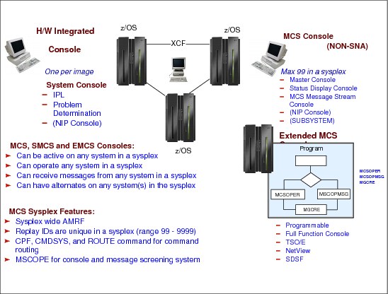
Figure 1-56 Multisystem consoles in a sysplex
Multisystem consoles in a sysplex
In a Parallel Sysplex implementation, there is no requirement that you have an MCS console on every system in the Parallel Sysplex. Using command and message routing capabilities, from one MCS, SMCS or extended MCS console, it is possible to control multiple z/OS in the Parallel Sysplex. Although MCS consoles are not required on all systems, you should plan the configuration carefully to ensure that there is an adequate number to handle the message traffic and to provide a valid configuration, regardless of the number of z/OSs in the Parallel Sysplex at a time.
If there is neither an MCS console nor an integrated system console on a system, that system probably cannot be the first to be IPLed into a sysplex; or a wait state would result. Alternate consoles must also be considered across the entire sysplex, especially for the sysplex master console. You should plan the console configuration so that there is always an alternate to the sysplex master console available at all times. If you do not do so, unnecessary operator action is required, and messages may be lost or sent to the hardcopy log, that is a log in the JES2 spool data set of all console traffic to be viewed by the auditors, if necessary.
A given computing operations environment can have a variety of different types of operators and different types of consoles. This chapter focuses primarily on the z/OS console operator’s tasks, and how the z/OS operator’s job might be different in a sysplex.
A z/OS console operator must start, run, and stop the z/OS operating system. That involves controlling z/OS system software, and the hardware it runs on, including processors, channel paths, and I/O devices. The operator might deal with messages and problems from many sources including z/OS, JES, DFSMS/z/OS, and other subsystems and products such as CICS, IMS, and VTAM, to name just a few. Some of the major tasks of operating the z/OS system include:
•Starting the system
•Controlling the system
•Controlling jobs
•Controlling system information recording
•Responding to failures
•Changing the configuration
•Providing problem determination data
•Quiescing the system
•Stopping the system
An operator in a single system environment is using multiple consoles to interact with the system.
In the sysplex environment the major tasks of operating the systems do not change very much. The potential exists that the number of consoles increase and the operator tasks become more repetitive and complex. This is caused by the fact that a sysplex has multiple z/OS images, each image with a set of subsystems and applications. Another effect is that this results in a flood of messages making system monitoring difficult.
The goal is to reduce the number of consoles that operators have to deal with. Suppress and reduce messages with automation software where possible. Use automation scripts to detect and react on standard malfunctions and system replies. Use graphical user interfaces (GUIs) to simplify the environment if possible.
Figure 1-56 on page 89 shows the three types of consoles:
Consoles in a sysplex
In a sysplex, a console can be active on any system in a sysplex and can provide sysplex-wide control. MCS uses XCF services for command and message transportation between systems and thus provides a single system image for the operators. MCS multisystem support features:
•Sysplex-wide action message retention facility (ARMF)
•Sysplex-wide unique reply IDs
•Sysplex-wide command routing through:
– ROUTE operator command
– Command prefix facility (CPF)
– CMDSYS setting for a console (through the CONSOLE statement in the CONSOLxx PARMLIB member or the CONTROL V,CMDSYS= operator command)
1.54 Sysplex operation and management
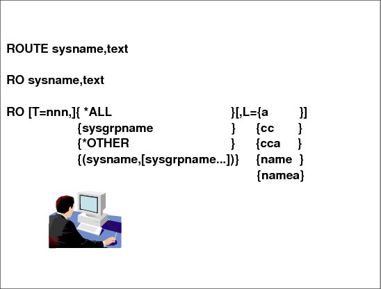
Figure 1-57 Sysplex operation and management
Sysplex operation and management
The following sections explain how the goals of single system image, single point of control, and minimal human intervention help to simplify the operator’s job in a sysplex.
Single system image and single point of control
Single system image allows the operator, for certain tasks, to interact with multiple images of a product as though they were one image. For example, the operator can issue a single command to all z/OS systems in the sysplex, instead of repeating the command for each system, using the z/OS ROUTE command.
Single point of control allows the operator to interact with a suite of products from a single workstation, without in some cases knowing which products are performing which functions.
Single point of control does not necessarily imply that you would have one single workstation from which all tasks by all people in the computing center would be done. But you could set things up so that each operator can accomplish a set of tasks from a single workstation, thereby reducing the number of consoles the operator has to deal with. If that workstation is also a graphical workstation where tasks can be performed by using a mouse to select ("click on") choices or functions to be performed, you have also reduced the complexity of performing the tasks.
One of the assumptions of single point of control is that you can receive messages from all systems on a single system. This does not happen automatically. We recommend that you set up most of your z/OS MCS consoles to receive messages from all systems, for the following reasons:
•You might need messages from multiple systems for diagnosing problems.
•Consolidating messages reduces the number of consoles you need.
Entering operator commands
z/OS operator commands can provide key data for problem analysis. The commands can be entered from the following consoles:
•The multiple console support (MCS) console
•The system console, a z/OS console emulated in the HMC
•The Hardware Management Console to interface with hardware
•The NetView console, an example of an EMCS console
The commands can also be issued by NetView automation CLISTs and by programs that use the extended MCS support.
Some commands have a sysplex scope, independent of any routing command or automation, while others can be routed to systems in the sysplex with the ROUTE command. For example, an operator can reply to message (WTOR) from any console in the sysplex, even if the console is not directly attached to the system that issued the message. Another example is certain forms of DISPLAY XCF and SETXCF commands.
If a problem management tool indicates a failure or an specific message, the operator can use DISPLAY commands that determine the detailed status of the failing system, job, application, device, system component, and so on. Based on the status, the operator has many commands to provide control and initiate actions; for example, the operator can enter commands to recover or isolate a failing resource.
ROUTE command
The operator can use the z/OS ROUTE command to direct a command to all systems in the sysplex (ROUTE *ALL), or a subset of the systems in the sysplex (ROUTE system_group_name). When issuing a command to multiple systems, the operator can receive a consolidated response to one console, rather than receiving responses from each system that must be located and correlated. RO is the short form of the command.
The syntax of the ROUTE command is shown in Figure 1-57 on page 91 and the meanings of the ROUTE parameters are as follows:
sysname The system name (1 to 8 characters) that will receive and process the command
text The system command and specific operands of the command being routed
T= This value is optional and indicates the maximum number of seconds z/OS waits for responses from each system before aggregating the responses. T is not valid when you specify just one sysname.
ALL Specifies that the command is to be routed to all systems in the sysplex.
OTHER Sends the command to all systems in a sysplex except the system on which the command is entered.
sysgrpname Routes the command to a subset of systems in the sysplex.
L Is optional and specifies the display area, console, or both, to display the command responses.
1.55 Displaying CF information

Figure 1-58 Displaying CF information
Displaying CF information
The command has several optional parameters, as follows:
D CF[,CFNAME={(cfname[,cfname]...)]
Use the DISPLAY CF command to display storage and attachment information about coupling facilities attached to the system on which the command is processed.
The DISPLAY CF command has local scope—it displays the CF hardware definition such as model and serial number, partition number, and so forth. In addition you will see the local system connections such as channels and paths.
When specified without further parameters, as in Figure 1-58, the system displays information about all coupling facilities that are attached. The output of the command in Figure 1-58 is only a partial paste.
1.56 Display XCF information (1)

Figure 1-59 Display XCF information (1)
Display XCF information (1)
Use the DISPLAY XCF command to display cross-system coupling information in the sysplex, as follows:.
•D XCF - displays active sysplex member names SCxx in the sysplex sandbox.
•D XCF,CF - displays active coupling facilities defined in the CFRM policy.
•D XCF,POLICY,TYPE=CFRM - displays active CFRM policy CFRM28 with start and update information. In our example the policy is in POLICY CHANGE(S) PENDING status.
1.57 Display XCF information (2)

Figure 1-60 Display XCF information (2)
Display XCF information (2)
The commands shown in Figure 1-60are as follows:
•The activation of a coupling facility resource management policy has caused pending policy changes to some coupling facility structures. The changes are pending the deallocation of the structure in a coupling facility.
– D XCF,STRUCTURE,STATUS=POLICYCHANGE - displays all structures in CFRM POLICY CHANGE PENDING state. A SETXCF START,REBUILD,STRNAME=strname command should resolve this status.
•The CFRM policy contains the maximum structure size and can contain a smaller initial size also. The initial structure size defined in the CFRM policy (or the maximum size if an initial size is not specified) is used as the attempted allocation size unless it is overridden by a structure size specified on the IXLCONN macro.
The CFRM policy can also optionally designate a minimum structure size. The MINSIZE value specifies the minimum bound for the structure size on all allocation requests except those resulting from system-managed rebuild.
– D XCF,STRUCTURE - displays all structures defined in the CFRM policy. Note that Figure 1-60 shows only a partial display.
1.58 Display XCF information (3)
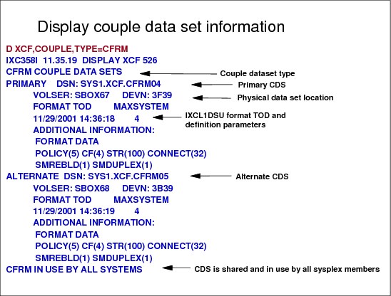
Figure 1-61 Display XCF information (3)
Display XCF information (3)
This command displays information about a CFRM couple data set (CDS) in use in the sysplex. The information includes:
•Physical attributes of the CFRM couple data set (name, volume serial number, device address, and time the data set was formatted)
•Maximum number of systems that the primary CFRM couple data set can support
•Names of the systems using the CFRM couple data set.
In Figure 1-61 the D XCF,COUPLE,TYPE=CFRM shows all relevant information about a specific CDS named CFRM.
Type=name
Here name specifies the name of the service using the CDS for which information is to be displayed. The name may be up to eight characters long. It may contain characters A-Z and 0-9 and the characters $, @, and # and must start with a letter . Supported names are:
•SYSPLEX for sysplex (XCF) types
•ARM for automatic restart management
•CFRM for coupling facility resource management
•SFM for sysplex failure management
•LOGR for the System Logger
•WLM for workload management
1.59 Display XCF signaling paths (1)
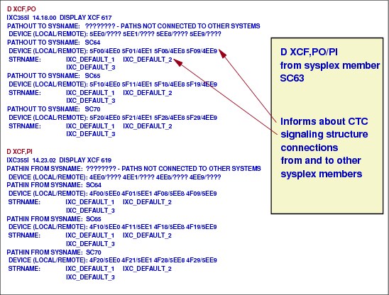
Figure 1-62 Display XCF signaling pathes (1)
Display XCF signaling paths (1)
D XCF,PI or D XCF,PO is useful for seeing all outbound and inbound connections from a sysplex member. Remember that these connections are defined in the COUPLExx member. In our example, Figure 1-62, you see signaling list structures and CTC connections making up our XCF communication paths.
Message IXC355I displays the device number of one or more outbound signaling paths that XCF can use, and information about outbound XCF signaling paths to this system. The display provides information for only those devices and structures that are defined to the system where this command is executed. The path summary response identifies each outbound path and, if known, the system name and device address of its associated inbound path. If specified without further qualification, summary information about all outbound XCF signalling paths is displayed. Use of the DEVICE,STRNAME or CLASS keyword requests that detail information be displayed.
If there are no outbound paths to this system, the system displays message IXC356I.
1.60 Display XCF signaling paths (2)
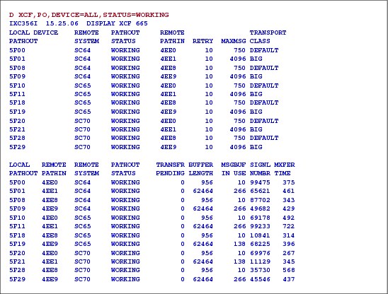
Figure 1-63 Display XCF signalling paths (2)
Display XCF signaling paths (2)
The D XCF,PO,DEVICE=ALL,STATUS=WORKING command shows, in list format, the outbound CTC devices and their inbound device number partners. It also gives an overview of the message classes and buffer sizes assigned to the CTC devices.
The second part of the display shows statistics if there is any transfer problem. There is no TRANSFER PENDING and the MXFER TIME in microseconds is below the recommended threshold value of 2000 or 2 milliseconds. MXFER is the mean transfer time for up to the last 64 signals received within the last minute. Values above 2 milliseconds may indicate that there is not enough CTC capacity. In this case RMF-based measurements should be done.
1.61 SETXCF command
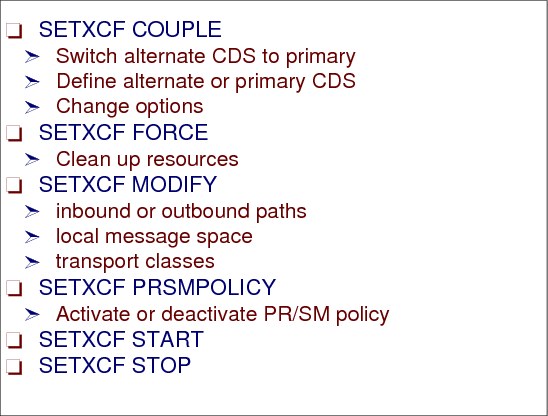
Figure 1-64 The SETXCF command
SETXCF command
The SETXCF command is used to control the sysplex environment. It has some variations, according to the action requested, as explained below.
SETXCF COUPLE
The SETXCF COUPLE command is used to:
•Switch a current alternate CDS to a primary CDS. The switch can be for either sysplex CDSs or other types of CDSs.
•Specify a primary non-sysplex CDS, such as CFRM, SFM, or WLM.
•Specify an alternate CDS.
•Change options specified in the COUPLExx parmlib member.
SETXCF FORCE
The SETXCF FORCE command is used to clean up resources related to structures in a CF. The resources can be either structures actively in use in the sysplex or dumps associated with structures pending deallocation.
SETXCF MODIFY
The SETXCF MODIFY command is used to change current XCF parameters. The system changes only those parameters explicitly provided on the SETXCF MODIFY command; all other parameters associated with the resource remain the same. You can use this to modify:
•Inbound paths
•Outbound paths
•Local message space
•Transport classes
SETXCF PFRSMPOLICY
The SETXCF PRSMPOLICY command is used either to activate an XCF PR/SM policy, or to deactivate a current active XCF PR/SM policy.
SETXCF START
The SETXCF START command is used to:
•Start new inbound signaling paths or restart inoperative inbound signaling paths.
•Start outbound signaling paths or restart inoperative outbound signaling paths.
•Define transport classes.
•Start using a new administrative policy as an active policy.
•Start rebuilding one or more CF structures either in the same CF or in another CF.
•Start populating a CF that has been newly brought into service or returned to service in a sysplex with structures selected from the set of those defined in the active CFRM policy. The structures selected are those that list the CF to be populated as higher in the structure’s preference list than the CF in which the structure already is allocated.
•Start user-managed duplexing of one or more structures in a CF into another CF.
•Start altering the size of a CF structure.
SETXCF STOP
The SETXCF STOP command is used to:
•Stop one or more inbound signaling paths.
•Stop one or more outbound signaling paths.
•Delete the definition of a transport class.
•Stop using an administrative policy.
•Stop rebuilding one or more CF structures.
•Stop populating a CF that had been newly brought into service in a sysplex with structures selected from the set of those defined in the active CFRM policy.
•Stop user-managed duplexing of one or more structures in a CF and specify the structure that is to remain in use.
•Stop altering a CF structure.
1.62 Managing the external timer

Figure 1-65 Managing external timer
Managing the external timer
To manage the external timer reference (ETR) you can use the following z/OS commands:
•DISPLAY ETR displays the current and status, in detail, of each ETR port, giving the ETR network ID, ETR port number, and the ETR ID. The complete syntax is:
D ETR,DATA
DATA is the default, so you can use just D ETR.
•SETETR PORT=nn can be used to enable ETR ports that have been disabled. An ETR port disabled by a hardware problem can be enabled after the problem has been corrected. PORT=nn specifies the number of the ETR port to be enabled. The valid values for n are 0 and 1.
•MODE is used to control the actions of recovery management when certain types of machine check interruptions occur. The actions you can control are recording/monitoring or suppressing status for each type of machine check interruption on the logrec system data set.
MODE AD The AD parameter defines machine checks indicating the ETR attachment is to be monitored in the specified mode.
MODE SC The SC parameter defines machine checks indicating the ETR synchronization checks are to be monitored in the specified mode.
1.63 Removing a system from the sysplex
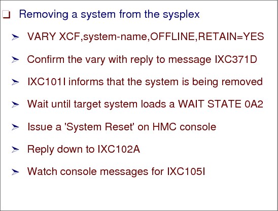
Figure 1-66 Removing a system from the sysplex
Removing a system from the sysplex
Removing a system from the sysplex means that:
•All XCF group members in the sysplex know that the system is being removed, so they can perform any necessary cleanup processing.
•All I/O to sysplex-shared resources is completed, to ensure data integrity.
•All signaling paths are configured to a desired state (retained or not).
Commands to remove a system
Use the VARY XCF command to remove a system from the sysplex. You can remove the system temporarily or permanently. To temporarily remove a system from the sysplex, issue:
VARY XCF,system-name,OFFLINE,RETAIN=YES
With RETAIN=YES (the default), MVS on each remaining system in the sysplex retains the definition of the devices for the signaling paths that connected to the removed system. Therefore, the removed system can be re-IPLed into the sysplex or another system can be added in its place, and MVS automatically starts the signaling paths. Note that the last system removed from the sysplex, remains defined to the sysplex couple data set. To permanently remove a system from the sysplex, issue:
VARY XCF,system-name,OFFLINE,RETAIN=NO
Reply to message IXC371D, which requests confirmation of the VARY XCF command. Message IXC101I then informs you that the system is being removed.
When the target system is in a wait state (issues message IXC220W with the wait state code 0A2), issue a system reset. The reset must be done after the wait state, to ensure the integrity of I/O to sysplex-shared I/O resources.
Reply DOWN to message IXC102A to continue removing the system from the sysplex.
After you reply, when the removal of the system is complete, message IXC105I is issued.
For more information about removing a z/OS system from a sysplex refer to the IBM Parallel Sysplex home page at:
1.64 Sysplex failure management (SFM)
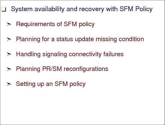
Figure 1-67 Sysplex failure management (SFM)
Sysplex failure management (SFM)
Sysplex failure management (SFM) allows you to define a sysplex-wide policy that specifies the actions that MVS is to take when certain failures occur in the sysplex. A number of situations might occur during the operation of a sysplex when one or more systems must be removed so that the remaining sysplex members can continue to do work. The goal of SFM is to allow these reconfiguration decisions to be made and carried out with little or no operator involvement.
Overview and requirements of SFM policy
If the sysplex includes a coupling facility, the full range of failure management capabilities that SFM offers is available to the sysplex. For SFM to handle signaling connectivity failures without operator intervention or to isolate a failing system, a coupling facility must be configured in the sysplex.
An SFM policy includes the following statements:
•Policy statement
•System statements
•Reconfiguration statements
Planning for a status update missing condition
If any system loses access to the SFM couple data set, the policy becomes inactive in the sysplex. If that system regains access to the SFM couple data set, SFM automatically becomes active again in the sysplex.
For a sysplex to take advantage of an SFM policy, the policy must be active on all systems in the sysplex. That is:
•All systems must be running a supported z/OS operating system.
•An SFM policy must be started in the SFM couple data set.
•All systems must have connectivity to the SFM couple data set.
Handling signaling connectivity failures
All systems in the sysplex must have signaling paths to and from every other system at all times. Loss of signaling connectivity between sysplex systems can result in one or more systems being removed from the sysplex so that the systems that remain in the sysplex retain full signaling connectivity to one another. SFM can eliminate operator intervention when signaling connectivity between two or more systems is lost.
Planning PR/SM reconfigurations
Loss of connectivity to a coupling facility can occur because of a failure of the coupling facility attachment or because of certain types of failures of the coupling facility itself. MVS provides the capability to initiate a rebuild of one or more structures in the coupling facility to which connectivity has been lost, using the CFRM policy and optionally, the SFM policy.
Setting up an SFM policy
The administrative data utility, IXCMIAPU allows you to associate the definitions with a policy name and to place the policy in a pre-formatted SFM couple data set.
To implement an SFM policy, you need to:
•Format an SFM couple data set and ensure that it is available to all systems in the sysplex.
•Define the SFM policy.
•Start the SFM policy in the SFM couple data set.
1.65 Parallel Sysplex complex

Figure 1-68 Parallel Sysplex complex
Parallel Sysplex complex
Until all systems are IPLed and join the sysplex, a mixed complex exists; that is, one or more of the systems in the global resource serialization complex are not part of the sysplex.
In multisystem sysplex mode, you need:
•A formatted primary sysplex couple data set shared by all systems in the sysplex.
•Signaling connectivity between all systems in the sysplex.
•The same Sysplex Timer for all systems in a sysplex that includes more than one CPC.
Sysplex status monitoring
Each system in the sysplex periodically updates its own status and monitors the status of other systems in the sysplex. The status of the systems is maintained in a couple data set (CDS) on DASD. A status update missing condition occurs when a system in the sysplex does not update its status information in either the primary or alternate couple data set within the failure detection interval, specified on the INTERVAL keyword in COUPLExx parmlib member, and appears dormant.
SFM allows you to specify how a system is to respond to this condition. System isolation allows a system to be removed from the sysplex as a result of the status update missing condition, without operator intervention, thus ensuring that the data integrity in the sysplex is preserved. Specifically, system isolation uses special channel subsystem microcode in the target CPC to cut off the target LP from all I/O and coupling facility accesses. This results in the target LP loading a non-restartable wait state, thus ensuring that the system is unable to corrupt shared resources.
SFM couple data set (CDS)
Sample JCL to run the format utility for formatting couple data sets for the sysplex failure management service is shipped in SYS1.SAMPLIB member IXCSFMF.
For an SFM couple data set, (DATA TYPE(SFM), valid data names are POLICY, SYSTEM, and RECONFIG.
ITEM NAME(POLICY) NUMBER( ) Specifies the number of administrative policies that can be defined.
(Default=9, Minimum=1, Maximum=50)
ITEM NAME(SYSTEM) NUMBER( ) Specifies the number of systems for which actions and weights can be defined. This should be the maximum number of systems that will be in the sysplex that the policy will govern. Note that the number specified does not need to include those systems identified by NAME(*), for which policy default values are applied.
(Default=8, Minimum=0, Maximum=32)
ITEM NAME(RECONFIG) NUMBER( ) Specifies the number of reconfigurations involving PR/SM partitions that can be specified.
Default=0, Minimum=0, Maximum=50)
Failure detection interval (FDI)
The failure detection interval (FDI) is the amount of time that a system can appear to be unresponsive before XCF will take action to remove the system from the sysplex. Internally we refer to this as the effective FDI, externally it is often designated by the word INTERVAL (referring to the INTERVAL parameter in COUPLExx parmlib member and on the SETXCF COUPLE command).
|
Note: It is recommended that the user let the system default the effective FDI to the SpinFDI by not specifying the INTERVAL keyword. The INTERVAL keyword allows customers to specify an effective FDI that is larger than the Spin FDI. When specified, the INTERVAL value should be at least as large as the SpinFDI to give the system enough time to resolve a spin loop timeout before it gets removed from the sysplex, but no so large that the rest of the sysplex suffers sympathy sickness.
|
Coupling facility
If the sysplex includes a coupling facility, the full range of failure management capabilities that SFM offers is available to the sysplex. For SFM to handle signaling connectivity failures without operator intervention or to isolate a failing system, a coupling facility must be configured in the sysplex.
1.66 Requirements of SFM policy
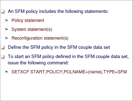
Figure 1-69 Requirements of SFM policy
Requirements of SFM policy
The SFM policy includes all the function available through XCFPOLxx parmlib member. If a system is connected to a couple data set with a started SFM policy, all XCFPOLxx parmlib member specifications on that system are deactivated, regardless of whether the SFM policy is active in the sysplex.
Because the SFM policy provides function beyond that provided by the XCF PR/SM policy, it is generally recommended that you use the SFM policy to manage failures in your sysplex. However, in cases where you cannot activate an SFM policy, activating an XCF PR/SM policy can be useful.
SFM allows you to define a sysplex-wide policy that specifies the actions that MVS is to take when certain failures occur in the sysplex. A number of situations might occur during the operation of a sysplex when one or more systems need to be removed so that the remaining sysplex members can continue to do work. The goal of SFM is to allow these reconfiguration decisions to be made and carried out with little or no operator involvement.
SFM policy
For a sysplex to take advantage of an SFM policy, the policy must be active on all systems in the sysplex. That is:
•An SFM policy must be started in the SFM couple data set.
•All systems must have connectivity to the SFM couple data set.
If any system loses access to the SFM couple data set, the policy becomes inactive in the sysplex. If that system regains access to the SFM couple data set, SFM automatically becomes active again in the sysplex.
|
Note: Similarly, if a system joins the sysplex where an SFM policy is active, the policy is disabled for the entire sysplex. When that system is removed from the sysplex, SFM automatically becomes active again in the sysplex.
|
Specifying an SFM policy in the CDS
The administrative data utility, IXCMIAPU allows you to associate the definitions with a policy name and to place the policy in a pre-formatted SFM couple data set.
To start an SFM policy (POLICY1, for example) that is defined in the SFM couple data set, issue the following command:
SETXCF START,POLICY,POLNAME=POLICY1,TYPE=SFM
|
Note: The SFM policy includes all the function available through XCFPOLxx parmlib member. However, if a system is connected to a couple data set with a started SFM policy, all XCFPOLxx parmlib member specifications on that system are deactivated, regardless of whether the SFM policy is active in the sysplex.
Because the SFM policy provides function beyond that provided by the XCF PR/SM policy, it is generally recommended that you use the SFM policy to manage failures in your sysplex. However, in cases where you cannot activate an SFM policy, activating an XCF PR/SM policy can be useful.
|
1.67 SFM implementation

Figure 1-70 SFM implementation
SFM implementation
Use the IXCMIAPU utility to define SFM policies and place them on the SFM couple data sets. An SFM policy can contain the following parameters:
•Specify PROMPT to notify the operator if a system fails to update its status in the sysplex couple data set (this results in the same recovery action as when SFM is inactive). The COUPLExx(OPNOTIFY) parameter controls when the operator is prompted.
|
Note: You cannot specify SSUMLIMIT if you specify the PROMPT parameter.
|
•Specify ISOLATETIME to automatically partition a system out of the sysplex if a system fails to update the sysplex couple data set with status.
•Specify CONNFAIL(YES) to automatically partition a system out of the sysplex if a system loses XCF signalling connectivity to one or more systems in the sysplex.
•DEACTTIME or RESETTIME can be used to automate recovery actions for system failures if a coupling facility is not available. ISOLATETIME is recommended instead of DEACTTIME or RESETTIME.
|
Note: PROMPT, ISOLATETIME, DEACTTIME and RESETTIME are mutually exclusive parameters. Use ISOLATETIME instead of RESETTIME/DEACTTIME because:
•ISOLATETIME is sysplex-wide. RESETTIME and DEACTTIME are effective only within a processor.
•ISOLATETIME quiesces I/O. RESETTIME and DEACTTIME imply a hard I/O reset.
|
Policy considerations
Consider the following guidelines when defining a policy:
•Assign weights to each system to reflect the relative importance of each system in the sysplex.
•The RECONFIG parameter can be used to reconfigure storage resources to a “backup” LPAR in the event of a production MVS failure.
•Use the SETXCF command to start and stop SFM policies.
•SFM accomplishes automatic removal of systems from the sysplex by performing a system isolation function (also known as fencing) for the system being removed. Fencing requires a coupling facility.
•When a system is shut down (planned), or if a system fails (unplanned), that system must be removed from the sysplex as soon as possible to prevent delays on other systems in the sysplex. Systems that are removed from the sysplex must not persist outside the sysplex (they must be fenced, system-reset, or disabled in some other manner such as powered off).
•SFM is a sysplex-wide function. Like CFRM, the SFM policy need only be started on one system in the sysplex to be active sysplex-wide.
•Only one SFM policy can be active at a time.
•Do not specify a DSN on the administrative data utility JCL.
•All active systems require connectivity to SFM couple data sets for the SFM policy to remain active.
•If SFM becomes inactive, PROMPT is reinstated as the recovery action initiated on a system failure.
•When PROMPT is specified or defaulted to, COUPLExx(OPNOTIFY) controls when IXC402D is issued.
1.68 SFM policy parameters
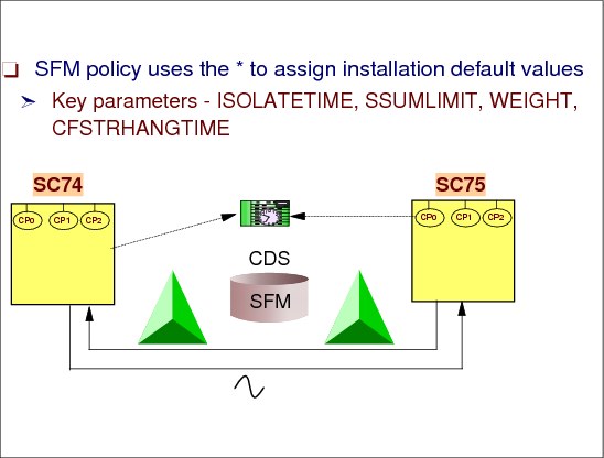
Figure 1-71 SFM policy parameters
SFM policy parameters
The following example shows the use of the * to assign installation default values in an SFM policy. There are many more parameters, but these are somewhat important.
With z/OS V1R12, the following parameters were changed to the values shown in Figure 1-72:
WEIGHT(25) - ISOLATETIME(0) - SSUMLIMIT(150) - CFSTRHANGTIME(300)
System SC74
In this example, system SC74 uses the following parameter values:
•It requires the ISOLATETIME value of 100 seconds and accepts the system default of SSUMLIMIT(NONE). The SSUMLIMIT(150) specified on the SYSTEM NAME(*) statement does not apply to SC74, because the SYSTEM NAME(SC74) statement specifies an indeterminate status action of ISOLATETIME(100).
•It uses policy default WEIGHT value of 10 and CFSTRHANGTIME value of 300 established by the SYSTEM NAME(*) statement.
•It uses the system defaults for all attributes not specified on either the SYSTEM NAME(SC74) or the SYSTEM NAME(*) statement, for example, MEMSTALLTIME(NO).
System SC75
System SC75 uses the following parameter values:
•It requires a WEIGHT value of 25.
•It uses the policy default combination of ISOLATETIME(0), SSUMLIMIT(150), and the policy default CFSTRHANGTIME value of 300 established by the SYSTEM NAME(*) statement.
It uses the system defaults for all attributes not specified on either the SYSTEM NAME(SC75) or the SYSTEM NAME(*) statement, for example, MEMSTALLTIME(NO).
All other systems
All other systems use the following parameter values:
•The policy default combination of ISOLATETIME(0) SSUMLIMIT(150), the policy default WEIGHT value of 10, and the policy default CFSTRHANGTIME value of 300 established by the SYSTEM NAME(*) statement.
•The system defaults for all other attributes, for example, MEMSTALLTIME(NO).
|
DEFINE POLICY NAME(POLICY1) ...
SYSTEM NAME(SC74)
ISOLATETIME(100)
SYSTEM NAME(SC75)
WEIGHT(25)
SYSTEM NAME(*)
WEIGHT(10)
ISOLATETIME(0) SSUMLIMIT(150)
CFSTRHANGTIME(300)
|
Figure 1-72 SFM policy parameters
Installation considerations
ISOLATETIME(0) is the default when none of the DEACTTIME, RESETTIME, PROMPT, or ISOLATETIME parameters is specified. IBM suggests using ISOLATETIME(0) to allow SFM to isolate and partition a failed system without operator intervention and without undue delay.
..................Content has been hidden....................
You can't read the all page of ebook, please click here login for view all page.