The idea of this recipe, which we'll call timerISR_c5v0, is to use a general purpose timer (TIM2) to generate an interrupt every 100 ms (that is, 10 Hz). The interrupt handler maintains a counter that, in turn, sets the global variables, LEDOn, LEDOff, which are used within main () to flash the LEDs.
Follow the steps to configure general purpose timers:
- Create a new recipe (folder) named
timerISR_c5v0. Invoke uVision5 and create a new project namedtimerISR.uvprojx. - Select the LED (API) driver from the RTE Board Support drop-down menu and configure CMSIS and Device options as in previous projects.
- Create a new file, name it
timerISR.c, and enter the following statements. Remember to include the boilerplate:#include ""stm32f4xx_hal.h"" #include ""Board_LED.h"" #include <stdbool.h> #include ""timer.h"" /* Globals */ uint32_t tic = 0; #ifdef __RTX ______________________________________________________ /* Function Prototypes */ void SystemClock_Config(void); /** * System Clock Configuration */ void SystemClock_Config(void) { ______________________________________________________ - Define a handler for the timer interrupt by adding these statements to the
timerISR.cfile:void TIM2_IRQHandler (void) { /* check IRQ source */ if ((TIM2->SR & 0x0001) != 0) { tic++; TIM2->SR &= ~(1<<0); /* clear UIF flag */ } } - Define a
main ()function in thetimerISR.cfile:int main (void) { int32_t num = 0; uint32_t toc; uint32_t count = 0; HAL_Init ( ); SystemClock_Config ( ); TIM2_Initialize ( );/* Gen. interrupt each 100 ms */ LED_Initialize(); /* LED Initialization */ while (1) { if (toc != tic) { toc = tic; LED_Off (num); if (count < 7) num = (num+1); else num = (num-1); LED_On (num); count = (count+1)%14; } } } - Open a new file, add the following source code, save the file, and name it
timer.c:/*-------------------------------------------------- * Recipe: timerISR_c5v0 * Name: timer.c * Purpose: Low level timer functions *-------------------------------------------------- * * Modification History * 16.04.14 created * 22.12.15 updated (uVision5.17+DFP2.6.0) * * Mark Fisher, CMP, UEA, Norwich *--------------------------------------------------*/ #include ""stm32f4xx_hal.h"" /* STM32F4xx Defs */ #include ""timer.h"" /**************************************************** * TIM2_Initialize ( ) **************************************************** * Initializes TIM2 generates interrupts every 100ms (0.1s) * SystemCoreClock = 168 MHz - set by SystemInit ( ) * Refer to Figure 134 of STM Reference Manual RM0090 * TIMxCLK = SystemCoreClock/2 * Hence ticks = 0.1 * 168,000,000 / 2 = 8,400,000 * Prescaler = 8400-1; ARR = 1000-1; *****************************************************/ void TIM2_Initialize (void) { const uint16_t PSC_val = 8400; const uint16_t ARR_val = 1000; RCC->APB1ENR |= RCC_APB1ENR_TIM2EN; /* En TIM2 clk */ TIM2->PSC = PSC_val - 1; /* set prescaler */ TIM2->ARR = ARR_val - 1; /* set auto-reload */ TIM2->CR1 = (1UL << 0); /* set command reg. */ TIM2->DIER = (1UL << 0); /* Enable TIM2 IRQ */ NVIC_EnableIRQ(TIM2_IRQn); /* En. NVIC TIM2 IRQ */ } - Add
timer.candtimerISR.cto the project. - Create a suitable header file named
timer.hcontaining function prototypes fortimer.c. - Build, download, and run the program.
As microcontrollers were conceived to target real-time applications, counter-timers have always been a prominent feature of their architecture. Timers can be used for a variety of purposes, including measuring pulse lengths of input signals, generating output signals, triggering interrupts, or other events. The STM32F407xx microcontroller family that is used by the evaluation board provides 14 timers (TIM1-TIM14).
|
Type |
Size |
Identifier |
|---|---|---|
|
Advanced Control Timers |
16-bit |
TIM1, TIM8 |
|
General Purpose Timers |
16/32-bit |
TIM2-TIM5 |
|
Basic Timers |
16-bit |
TIM6, TIM7 |
|
General Purpose Timers |
16-bit |
TIM9-TIM14 |
A simplified schematic for general purpose timers is shown in the following diagram (a more detailed schematic can be found in STM's RM0090 Reference manual at http://www.st.com).

Advanced timers, TIM1 and TIM8, provide similar functionality and include some additional features, such as a repetition counter, break inputs, and complementary outputs with programmable dead time. These are useful when implementing complex pulse width modulation (PWM) schemes. The main component is the time-base unit comprising a 16/32-bit counter and its related auto-reload register and prescaler. The prescaler clock (CK_PSC) can be selected from one of the following:
- Internal clock (CK_INT): This is derived from the reset and clock control (RCC) peripheral.
- External clock mode 1: This is the External input pin (TIx)
- External clock mode 2: The External trigger input (ETR) is available on TIM2, TIM3, and TIM4, only
- Internal trigger inputs (ITRx): This allows one timer to act as a prescaler for another
Following RESET, the CK_INT internal clock is selected. CK_INT is derived from the APBx timer output of the Reset and Clock Control (RCC) unit; refer to STM's RM0090 Reference manual, Figure 21, (http://www.st.com). The timer clock frequencies are set automatically by hardware. The frequency depends on the setup used for the APB domain prescaler. There are two cases, as follows:
- If the APB prescaler is 1, the timer clock frequencies are set to the same frequency as that of the APB domain to which the timers are connected
- Otherwise, they are set to twice (×2) the frequency of the APB domain to which the timers are connected
The RCC unit manages all the clocks used by the microcontroller. The system clock (SYSCLK) can be derived from one of three sources:
- HSI clock
- HSE clock
- PLL clock
The SystemInit( ) function defined in the system_stm32f4xx.c file is called by the startup_stm32f4xx.s file to configure the system clock before branching to the main program. The SystemCoreClock global variable is assigned a value representing the SYSCLK frequency and is available to user applications (for example, to set the SysTick timer). SystemInit() also configures the AHB and APB domain prescalers.
The internal (HIS) clock and external crystal-controlled oscillator (HSE) clock are connected to the main phase locked loop (PLL) within the microcontroller and this provides two outputs:
- The first output is used to generate the high-speed system clock (upto 168 MHz)
- The second output is used to generate the clock for the USB OTG FS (48 MHz), the random analog generator (≤48 MHz), and the SDIO (≤48 MHz)
The MCBSTM32F400 evaluation board uses a 25 MHz external oscillator, which gives a PLL frequency of 168 MHz, and SystemInit () selects this as SYSCLK.
The main component of the time-base unit is a 16-bit or 32-bit counter (CNT) and its associated auto-reload register (ARR). The counter clock can be divided by a prescaler (PSC). Both the counter, prescaler, and auto-reload register can be written or read by software. The prescaler can divide the counter clock frequency by any factor between 1 and 65,536 (216). The operation of the counter and auto-reload register depends on the how the counter is configured. Three configuration modes are available, named upcounter, downcounter, and center-aligned. The timing diagram shown next illustrates the upcounter mode with the prescaler set to divide by 2 (other modes are described in the RM0090 Reference manual, http://www.st.com). In upcounting mode, the counter counts from 0 to the auto-reload value (the content of the TIMx_ARR register), then restarts from 0 and generates a counter overflow event.

The steps required to configure TIM2 are as follows:
- First enable the
TIM2clock by writing to theRCC APB1Enable Register:RCC->APB1ENR |= RCC_APB1ENR_TIM2EN;
The number of SYSCLK ticks in 0.1 s can be found by:
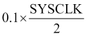
when SYSCLK = 168 MHz this gives a value of 8,400,000, which is achieved by a prescaler value of 8,400 and auto-reload register value of 1,000, that is, as follows:
const uint16_t PSC_val = 8400;
const uint16_t ARR_val = 1000;
The prescaler divides the input clock by a factor PSC[15:0] +1:

So we write the following
TIM2->PSC = PSC_val - 1;
- Similarly, as the counter is reset to zero, we write the following:
TIM2->ARR = ARR_val -1;
- Then, enable the counter and enable interrupts:
TIM2->CR1 = (1UL << 0);
TIM2->DIER = (1UL << 0);
- Finally, configure the Nested Vectored Interrupt Controller to respond to
TIM2interrupts:NVIC_EnableIRQ(TIM2_IRQn);
Once configured, Timer 2 generates interrupts every 100 ms, and the interrupt handler increments a counter (tic). The code within the superloop generates a visually interesting pattern.