The camera is another I2C peripheral, but to display video we need to read the array pixels that make up an image and write their values to the GLCD very rapidly. We achieve this by using Direct Memory Access (DMA) to stream image frames directly to the GLCD rather than writing individual values as we did for the audio codec demo. We'll name this recipe cameraDemo_c6v0.
- Create a new project named
cameraDemo. Using the RTE manager, go to Board Support and select the Camera (API) and Graphic LCD (API) software components. - Set the CMSIS and Device software components, as we've done for previous projects. Set the Use MicroLIB project option.
- Create a file named
cameraDemo.cand add boilerplate code to configure clocks, and so on. Add this file to the project. - Add a
main()function to thecameraDemo.cfile: - Build, download, and run the program, as follows:
int main (void) { uint32_t addr; HAL_Init(); /* Initialize the HAL Library */ SystemClock_Config(); /* Config System Clk */ GLCD_Initialize(); /* Graphical Display Init */ /* Get fremebuffer addr */ addr = GLCD_FrameBufferAddress(); Camera_Initialize(addr); /* Camera Init */ /* Prepare display for video stream from camera */ GLCD_SetBackgroundColor (GLCD_COLOR_BLUE); GLCD_ClearScreen (); GLCD_FrameBufferAccess (true); /* Turn camera on */ Camera_On (); while (1) { ; /* Nothing to do here; all done by DMA */ } } - Open the
RTE_Device.hfile and use the configuration wizard to set the I2C port parameters. Remember to check the DMA transmit and receive options (we can accept the default DMA parameters):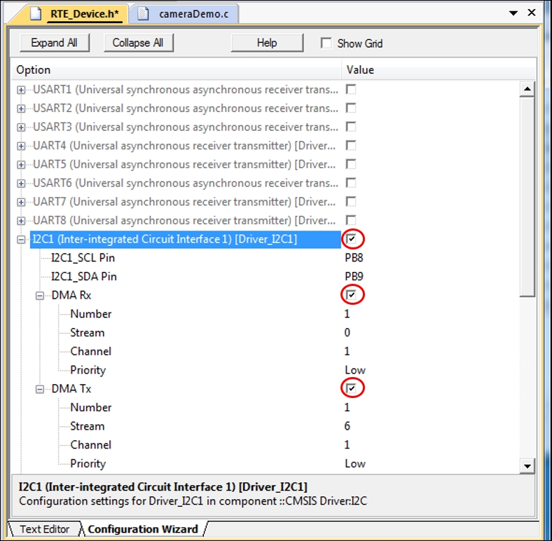
- Build the project, then download and run the program.
As the camera is another I2C peripheral and the driver (API) named Camera_OVM7690.c provided by ARM is structured in a similar way to that for the touchscreen and audio codec, the array named Camera_RegInit [ ] stores a number of addresses and value pairs that are written by the function named Camera_Initialize(). The camera used on the evaluation board is an OVM7690 part manufactured by OmniVision (http://www.ovt.com). The camera resolution is 640 × 480 pixels and operates at up to 30 frames per second (fps). We need to access OmniVision's OVM7690 Software Application Note in order to understand the code used to initialize the camera, but currently, these documents are company-confidential and protected by Non-Disclosure Agreements (NDAs). The camera is aimed at mobile phone, notebook, and automotive applications and includes a number of programmable controls for image-processing functions, such as exposure, gamma, white balance, hue, and so on. Camera_Initialize() also configures a DMA channel to stream data from the camera to SDRAM, so it needs to be provided with the base address of a memory segment. This address is defined by the GLCD (API) and acquired by the GLCD_FrameBufferAddress ( ) function.
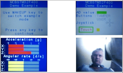
A demo project that exercises many of the features of the MCBSTM32F400 evaluation board can be downloaded by the pack installer with the Device Family Pack (currently the version is DFP 2.6.0). As the demo program displays icons on the GLCD that are encoded as bitmaps, the executable image for the program exceeds the limit imposed by the evaluation version of the uVision IDE. This code is read-only, but it has been precompiled so that the project can be downloaded and run on the board.
The main function declared in the demo.c file implements a finite-state machine (FSM) that determines the operating mode of the program. An integer variable named
mode is assigned a value of 0, 1, 2, or 3 depending on the mode that was selected. These modes are mapped to the M_INIT, M_STD, M_MOTION, and M_CAM literals by the enumerated type definition:
/* Mode definitions */
enum {
M_INIT = 0,
M_STD,
M_MOTION,
M_CAM,
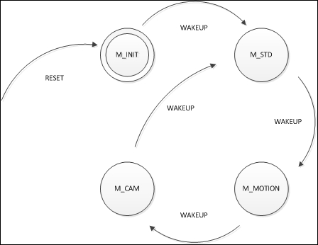
};The mode variable is assigned by the function called SwitchMode() that takes an input argument that identifies the current state (that is, 0, 1, 2, and 3) and returns the next state. For example, the first call to SwitchMode() is made when the current state is M_INIT:
mode = SwitchMode (M_INIT);
A switch statement in main() determines different behaviors for each mode, as follows:
switch (mode) {
case M_STD:
    ...
break;
case M_MOTION:
    ...
break;
case M_CAM:
    ...
break;
default:
mode = SwitchMode (mode);
break;
}
This behavior is better described by a state diagram (shown as follows). This diagram is a graph where states are identified by vertices and the permitted transitions between states by edges. The edges are labeled with events that give rise to the changes of state.
The Demo project is a very useful resource as it provides example code for many of the evaluation board functions. The #include statements at the start of the main source file provide some insight into what is available: