Running without an operating system
Keywords
Exception processing; AArch64; Exception states; The boot process; Bare metal program; Interrupt; ARM processor
The previous chapters assumed that the software would be running in user mode under an operating system. Sometimes, it is necessary to write assembly code to run on “bare metal,” which simply means: without an operating system. For example, when we write an operating system kernel, it must run on bare metal and a significant part of the code (especially during the boot process) must be written in assembly language. Coding on bare metal is useful to deeply understand how the hardware works and what happens in the lowest levels of an operating system. There are some significant differences between code that is meant to run under an operating system and code that is meant to run on bare metal.
The operating system takes care of many details for the programmer. For instance, it sets up the stack, text, and data sections, initializes static variables, provides an interface to input and output devices and gives the programmer an abstracted view of the machine. When accessing data on a disk drive, the programmer uses the file abstraction. The underlying hardware only knows about blocks of data. The operating system provides the data structures and operations which allow the programmer to think of data in terms of files and streams of bytes. A user program may be scattered in physical memory, but the hardware memory management unit, managed by the operating system, allows the programmer to view memory as a simple memory map (such as shown in Fig. 1.7). The programmer uses system calls to access the abstractions provided by the operating system. On bare metal, there are no abstractions, unless the programmer creates them.
However, there are some software packages to help bare-metal programmers. For example, Newlib is a C standard library intended for use in bare-metal programs. Its major features are that:
- • it implements the hardware-independent parts of the standard C library,
- • for I/O, it relies on only a few low-level functions that must be implemented specifically for the target hardware, and
- • many target machines are already supported in the Newlib source code.
To support a new machine, the programmer only has to write a few low-level functions in C and/or Assembly, which will initialize the system and perform low-level I/O on the target hardware.
12.1 Exception processing
Many early computers were not capable of protecting the operating system from user programs. That problem was solved mostly by building CPUs that support multiple “levels of privilege” for running programs. Almost all modern CPUs have the ability to operate in at least two modes:
User mode is the mode that normal user programs use when running under an operating system, and
Privileged mode is reserved for operating system code or exception handling. There are operations that can be performed in privileges mode which cannot be performed in user mode.
Many bare metal programs consist of a single thread of execution running in user mode to perform some task. This main program is occasionally interrupted by the occurrence of some exception. The exception is processed, and then control returns to the main thread. The main thread usually runs with user privileges, and exception processing is done in privileged mode.
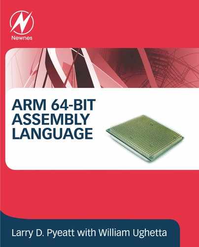
Fig. 12.1 shows the sequence of events when an exception occurs in such a system. The main program typically would be running with the CPU in user mode. When the exception occurs, the CPU uses the vector table to find and execute the appropriate exception handler. Different CPU architectures have different methods for implementing vector tables, but all modern CPUs support some type of vector table. The exception handler must save any registers that it is going to use, execute the code required to handle the exception, then restore the registers. When it returns to the user mode process, everything will be as it was before the exception occurred. The user mode program continues executing as if the exception never occurred.
More complex systems may have multiple tasks, threads of execution, or user processes running concurrently. In a single-processor system, only one task, thread, or user process can actually be executing at any given instant, but when an exception occurs, the exception handler may change the currently active task, thread, or user process. This is the basis for all modern multi-processing systems. Fig. 12.2 shows how an exception may be processed on such a system. It is common on multi-processing systems for a timer device to be used to generate periodic interrupts, which allows the currently active task, thread, or user process to be changed at a fixed frequency.

Privileged mode is entered automatically by the hardware when certain exceptional circumstances occur. For example, when a hardware device needs attention, it can signal the processor by causing an interrupt. When this occurs, the processor immediately sets the appropriate exception level and begins executing the IRQ exception handler function. The exception handlers (or their addresses) are stored in a vector table at a known location in memory. When an exception occurs, the CPU automatically uses the vector table to find and execute the appropriate exception handler function.
12.2 AArch64 execution and exception states
The AArch64 processor provides two major modes of operation, referred to as execution states. They are 32-bit AArch32 state, and 64-bit AArch64 state. Both of these execution states provide privileged modes and a user mode. The AArch32 execution state allows the processor to execute code written for the ARMv7 and older processors.
12.2.1 AArch64 exception levels
In the AArch64 execution state, there are three privileged modes and one user mode. These are referred to as exception levels. The higher the exception level, the more privilege the code has. Typically, the system uses the exception levels as follows:
EL0 User applications,
EL1 OS kernel and other privileged code,
EL2 Hypervisor (support for virtual machines), and
EL3 Secure monitor (manage security contexts).
The major difference between EL0 and the higher levels is that code executing in EL0 cannot access system registers. EL1 can access most system registers, EL2 has additional privileges, and EL3 has all privileges. The only way that the processor can change from one exception level to a higher level is when an exception occurs. The only way that the processor can move to a lower exception level is by executing an exception return instruction. When changing the exception level, it is also possible to switch between AArch64 and AArch32 execution state. The processor also supports two security states: Secure and non-secure. EL3 is meant to manage the security state, and EL2 is meant to provide virtual machine capabilities. In many situations, only EL0 and EL1 are required, and some processors may not provide EL2 and/or EL3. On power-up and on reset, the processor enters the highest available exception level.
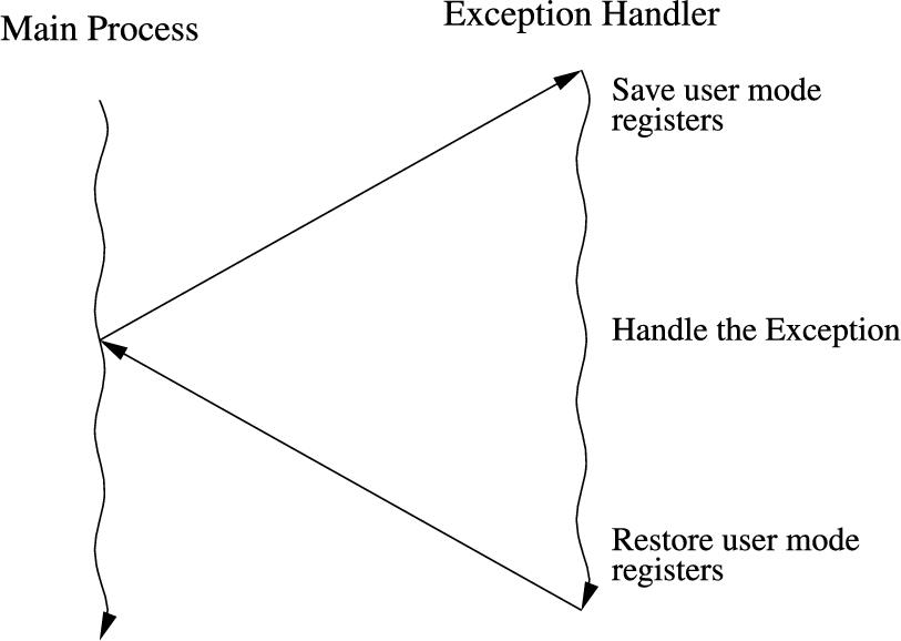
Each exception level has its own stack pointer, link register, and saved process state register (SPSR). Table 12.1 shows the names of these banked registers. When the exception level changes, the corresponding link register and stack pointer become active, and “replace” the user stack pointer and link register. Also, when an exception occurs, the current PSTATE register is copied into the SPSR for the exception level that is being entered. When an exception occurs:
- 1. The current PSTATE is copied to SPSR_ELn where n is the exception level being entered,
- 2. the PSTATE register is updated,
- 3. the exception level stays the same or gets higher,
- 4. the return address is stored to ELR_ELn,
- 5. the program counter (PC) is set to the appropriate vector address, and
- 6. if it is a synchronous or SError exception, ESR_ELn is updated with the cause of exception.
To return from an exception, the ![]() instruction is executed. This instruction:
instruction is executed. This instruction:
- 1. restores the
 from
from  , and
, and - 2. restores the program counter (PC) from
 .
.
Software executing in an exception level higher than EL0 can select whether to use the default SP_ELx stack pointer or the SP_EL0 stack pointer by executing an
Table 12.1
The ARM User and System Registers.
| EL0 | EL1 | EL2 | EL3 | |
|---|---|---|---|---|
| Stack Pointer | SP_EL0 | SP_EL1 | SP_EL2 | SP_EL3 |
| Exception Link Register | ELR_EL1 | ELR_EL2 | ELR_EL3 | |
| Saved PSTATE | SPSR_EL1 | SPSR_EL2 | SPSR_EL3 |
![]()
instruction. This allows privileged code to access and modify the user mode stack. For example, when an exception occurs, registers can be saved on the user mode stack, then restored before going back to user mode.
12.2.2 System control and status registers
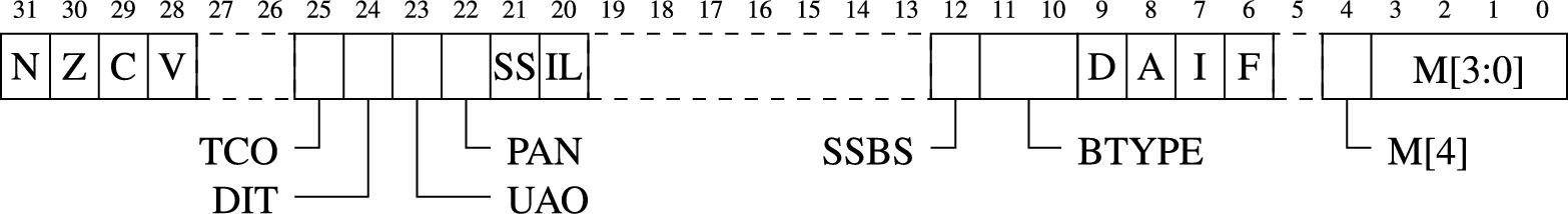
The PSTATE flags were introduced in Chapter 3. The PSTATE register also contains other fields that are used by system (or bare metal) code. Fig. 12.3 shows all of the fields in the PSTATE register. These fields are briefly described below:
TCO Tag Check Override is available in ARMv8.5 and above with the MemTag extension.
DIT Data Independent Timing is available in ARMv8.4 and above with the DIT extension.
UAO User Access Override is available in ARMv8.2 and above with the UAO extension.
PAN Privileged Access Never is available in ARMv8.1 and above with the PAN extension.
SS Software Step.
IL Illegal Execution state.
SSBS Speculative Store Bypass is available in ARMv8.0 and above with the SSBS extension.
BTYPE Branch Type Indicator is available in ARMv8.5 and above with the BTI extension.
D Debug exception mask.
A SError interrupt mask.
I IRQ interrupt mask.
F FIQ interrupt mask.
M[4] Execution state (Mode bit 4). A zero in this bit indicates AArch64 state. One indicates AArch32 state.
M[3:0] AArch64 Exception level and selected Stack Pointer. The values for this field are shown in Table 12.2
Table 12.2
| M[3:0] | EL | SP |
|---|---|---|
| 0000 | EL0 | SP_EL0 |
| 0100 | EL1 | SP_EL0 |
| 0101 | EL1 | SP_EL1 |
| 1000 | EL2 | SP_EL0 |
| 1001 | EL2 | SP_EL2 |
| 1100 | EL3 | SP_EL0 |
| 1101 | EL3 | SP_EL3 |
The most important fields are the Mode bits, which can be examined to determine which stack pointer is currently selected, which execution state the processor is in, and the current exception level. Some of the fields can also be changed by code running in privileged mode. Table 12.2 shows valid values for the Mode bits.
For exception levels other than EL0, the execution state (AArch32 or AArch64) is determined by one or more control register configuration bits. These bits can be set only in execution states higher than EL0. For EL0, the execution state is determined as part of the exception return to EL0, under the control of the exception level that the execution is returning from. Higher exception levels can change the execution state, but EL0 cannot.
There are some additional configuration and status registers available in higher exception levels. They include:
SCTLR_ELn The System Control Register controls architectural features. For example the Memory Management Unit (MMU), caches, and memory alignment checking.
ACTLR_ELn The Auxiliary Control Register controls processor specific features.
SCR_EL3 The Secure Configuration Register controls secure state and trapping of exceptions to EL3.
HCR_EL2 The Hypervisor Configuration Register controls virtualization settings, and trapping of exceptions to EL2.
MIDR_EL1 The Main ID Register describes the type of processor the code is running on.
MPIDR_EL1 The Multiprocessor Affinity Register contains the core and cluster ID of the core/cluster that the code is running on, in multi-core/cluster systems.
CTR_EL0 The Cache Type register contains information about the integrated caches.
12.3 AArch64 vector table
In AArch64, exceptions are divided into two major types:
Synchronous exceptions are synchronized with the CPU clock. This type of exception includes data aborts from MMU, permission/alignment failures for load and store operations, service call instructions, and illegal instructions.
Asynchronous exceptions may occur at any time, and may not be synchronized with the CPU clock. These exceptions include interrupt requests (IRQ and FIQ) from external devices, or SError (System Error) interrupts.
When an exception is processed, the exception level can stay the same or go to a higher exception level. If an exception occurs in EL0, then the new exception level must be higher than EL0. Synchronous exceptions are normally handled in the current exception level, except for EL0. Asynchronous exceptions can be routed to a higher exception level. Preparing to handle exceptions requires:
- • setting up the vector table, and
- • configuring asynchronous exception routing and masking.
Each exception must be handled by a dedicated function. Each function in the vector table may have up to 32 instructions. If the exception handler is more than 32 instructions, then a branch instruction is used to jump to a longer exception handler. Each exception level except for EL0 has its own vector table. The addresses of the vector tables are stored in three registers: VBAR_EL3, VBAR_EL2, and VBAR_EL1. Each vector table has sixteen entries, and each entry is 128 bytes long, giving room for 32 instructions. Vector tables must be aligned to a 2 kilobyte boundary.
Fig. 12.4 shows how each vector table is structured. Note that the figure has the lowest address at the bottom. When writing the assembly code, the bottom entry in the table comes first, so that it gets the lowest address (at offset 0x000 from the start of the table. It is followed by the handler that is to be placed at 0x080, relative to the start of the table, and so on.

12.3.1 Creating the vector tables
Listing 12.1 shows 16 functions making up one vector table. Each exception level, (EL1, EL2, and EL3) may have it's own vector table, for a total of 48 exception handler functions. Note that each exception handler ends with an ![]() (exception return) instruction. Up to 31 instructions can be inserted before the exception return instruction. If more instructions are needed, then they can be placed in a subroutine, and a
(exception return) instruction. Up to 31 instructions can be inserted before the exception return instruction. If more instructions are needed, then they can be placed in a subroutine, and a ![]() instruction can be inserted in the vector table code.
instruction can be inserted in the vector table code.

12.3.2 Using the vector tables
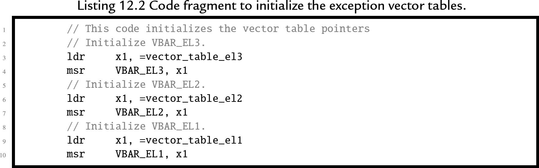
Listing 12.2 shows how the processor is initialized to use the vector tables. This listing assumes that three vector tables have been created, each of which follows the pattern shown in Listing 12.1. The three vector table pointer registers are initialized by loading the address of a vector table into a general purpose register, then transferring the address to a vector table register.
12.3.3 Configuring asynchronous exceptions
Asynchronous exceptions, or “hardware interrupts” may occur at any time, and are used by hardware devices to signal that they require service. On the AArch64 processor, there are three bits in the PSTATE register which affect asynchronous exception processing:
I: when set to one, normal hardware interrupts are disabled,
F: when set to one, fast hardware interrupts are disabled, and
A: when set to one, system error interrupts are disabled.
Programs running in EL0 cannot modify these bits. Therefore, the operating system is guaranteed to gain control of the CPU whenever an interrupt occurs. The user program cannot disable interrupts and continue to run. Most operating systems use a hardware timer to generate periodic interrupts, thus the operating system is able to regain control of the CPU every few milliseconds. This prevents a malicious or defective user program from taking control of the CPU.
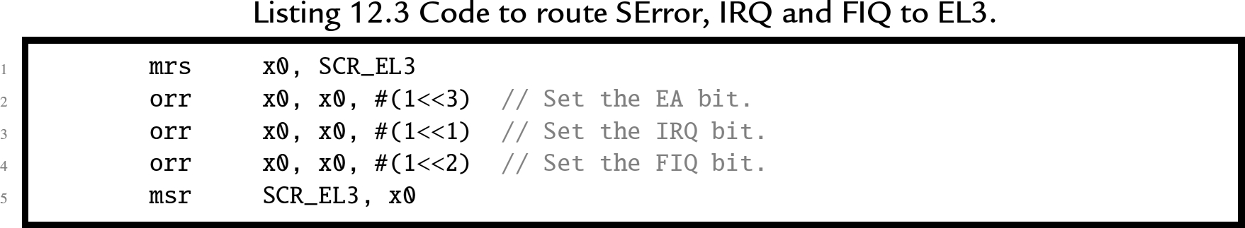
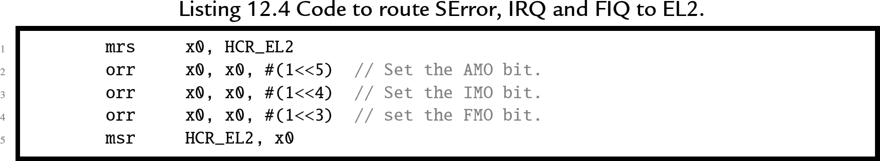
On startup or reset, the asynchronous exceptions are disabled. Before they can be enabled, routing rules must be set, and external devices must be configured to signal interrupts. Section 12.6.2 provides an overview of configuring the interrupt controller on the Raspberry Pi. By default, all asynchronous exceptions are routed to EL1. SCR_EL3 specifies exceptions to be routed to EL3 Listing 12.3 shows how to route all three asynchronous exceptions to EL3, and HCR_EL2 specifies exceptions to be routed to EL2. Listing 12.4 shows how to route all three asynchronous exceptions to EL2. For both control registers, separate bits to control routing of IRQs, FIQs, and SErrors.
Asynchronous exceptions may be masked by setting the A, I, and F bits in the PSTATE register to one. Additionally, when a target exception level is lower than the current exception level, the asynchronous exception is masked implicitly. The asynchronous exception will not be processed until it is unmasked by clearing the appropriate bit in the PSTATE register, and/or entering an exception level less than or equal to the exception level that the asynchronous exception is routed to. When the target exception level is higher than the current exception level, and the target exception level is EL2 or EL3, the asynchronous exception is processed, regardless of the settings in the PSTATE register. Listing 12.5 shows how to enable asynchronous exceptions by clearing the A, I, and F, bits in the PSTATE register. To set the bits, use DAIFSet instead of DAIFClr.

12.4 The boot process
In order to create a bare metal program we must understand the processor does when power is first applied or after a reset. The ARM CPU begins to execute code at a predetermined address which depends on the configuration of the CPU. In order for the system to work, the startup code must be at the correct address when the system starts up.
On the Raspberry Pi, when power is first applied, the ARM CPU is disabled and the Graphics Processing Unit (GPU) is enabled. The GPU runs a program that is stored in flash memory or ROM. That program, called the first stage boot loader, reads the second stage boot loader from a file named (bootcode.bin) on the SD card. That program enables the SDRAM, and then loads the third stage bootloader, start.elf. At this point, some basic hardware configuration is performed, and then the kernel is loaded to address 0x8000 from the kernel8.img file on the SD card. Once the kernel image file is loaded, a “![]() ” instruction is placed at address 0, and the ARM CPU is enabled. The ARM CPU executes the branch instruction at address 0, which immediately jumps to the kernel code at address 0x8000.
” instruction is placed at address 0, and the ARM CPU is enabled. The ARM CPU executes the branch instruction at address 0, which immediately jumps to the kernel code at address 0x8000.
To run a bare metal program on the Raspberry Pi, it is only necessary to build an executable image and store it as kernel8.img on the SD card. Then, the boot process will load the bare metal program instead of the Linux kernel image. Care must be taken to ensure that the linker prepares the program to run at address 0x8000 and places the first executable instruction at the beginning of the image file. It is also important to make a copy of the original kernel image, so that it can be restored (using another computer). If the original kernel image is lost, then there will be no way to boot Linux until it is replaced.
12.5 Writing a bare metal program
A bare metal program should be divided into several files. Some of the code may be written in assembly, and other parts in C or some other language. The initial startup code, and the entry and exit from exception handlers, must be written in assembly. However, it may be much more productive to write the main program and the remainder of the exception handlers as C functions and have the assembly code call them.
12.5.1 Startup code
On startup or reset, the processor begins execution in EL3. The bare-metal program must include some start-up code. The startup code will:
- • initialize the stack pointers for all of the modes,
- • set up interrupt and exception handling,
- • initialize the
 section,
 - • configure the CPU and critical systems (optional),
- • set up memory management (optional),
- • set up process and/or thread management (optional),
- • initialize devices (optional), and
- • branch to
 .
.
The startup code requires some knowledge of the target platform, and at least part of it must be written in assembly language. The following listing shows a function named ![]() which sets up the stacks, initializes the .bss section, sets up the vector tables, then calls the
which sets up the stacks, initializes the .bss section, sets up the vector tables, then calls the ![]() function:
function:

The first task of the startup code is to set all bytes in the ![]() section to zero. Recall that the
section to zero. Recall that the ![]() section is used to hold data that is initialized to zero, but that the program file does not actually contain all of the zeros. Programs running under an operating system can rely on the C standard library to initialize the
section is used to hold data that is initialized to zero, but that the program file does not actually contain all of the zeros. Programs running under an operating system can rely on the C standard library to initialize the ![]() section. If it is not linked to a C library, then a bare metal program must set all of the bytes in the
section. If it is not linked to a C library, then a bare metal program must set all of the bytes in the ![]() section to zero for itself.
section to zero for itself.
The second task for the startup code is to initialize the vector table and stack pointer for each exception level. When an exception or interrupt occurs, the processor will automatically change into the appropriate exception level and begin executing an exception handler, using the stack pointer for that exception level. Hardware interrupts can be masked, but synchronous exceptions cannot be disabled. In order to guarantee correct operation, a stack must be set up for each exception level, and an exception handler must be provided. The exception handler does not actually have to do anything.
On the Raspberry Pi 2 and 3, memory is mapped to begin at address 0, and all models have at least 512 megabytes of memory. Therefore, it is safe to assume that the last valid memory address is 0x01FFFFFFF. If each exception level is given eight kilobytes of stack space, then all of the stacks together will consume 32 kilobytes, and the initial stack addresses can be easily calculated. Since the C compiler uses a full descending stack, the initial stack pointers can be assigned addresses 0x20000000, 0x01FFFE000, 0x01FFFC000, etc.
After initializing the ![]() section and setting up the stacks and vector tables, the startup code switches to EL0 and calls the
section and setting up the stacks and vector tables, the startup code switches to EL0 and calls the ![]() function. The main thread will run with user privilege, and exceptions will cause the CPU to go to EL1 and begin executing the exception handler.
function. The main thread will run with user privilege, and exceptions will cause the CPU to go to EL1 and begin executing the exception handler.
12.5.2 Main program
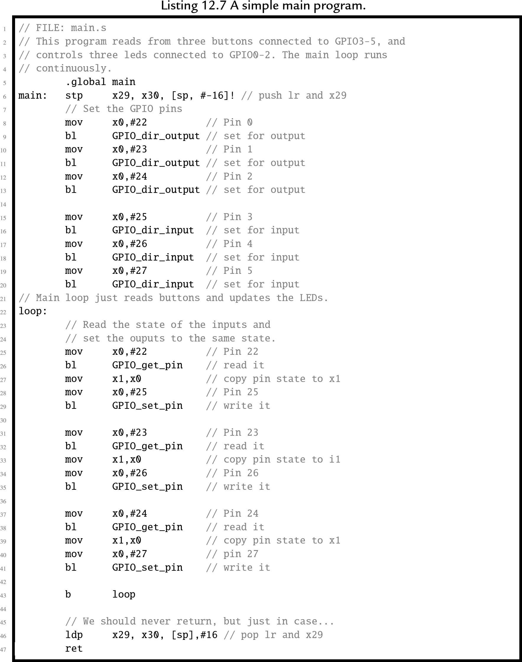
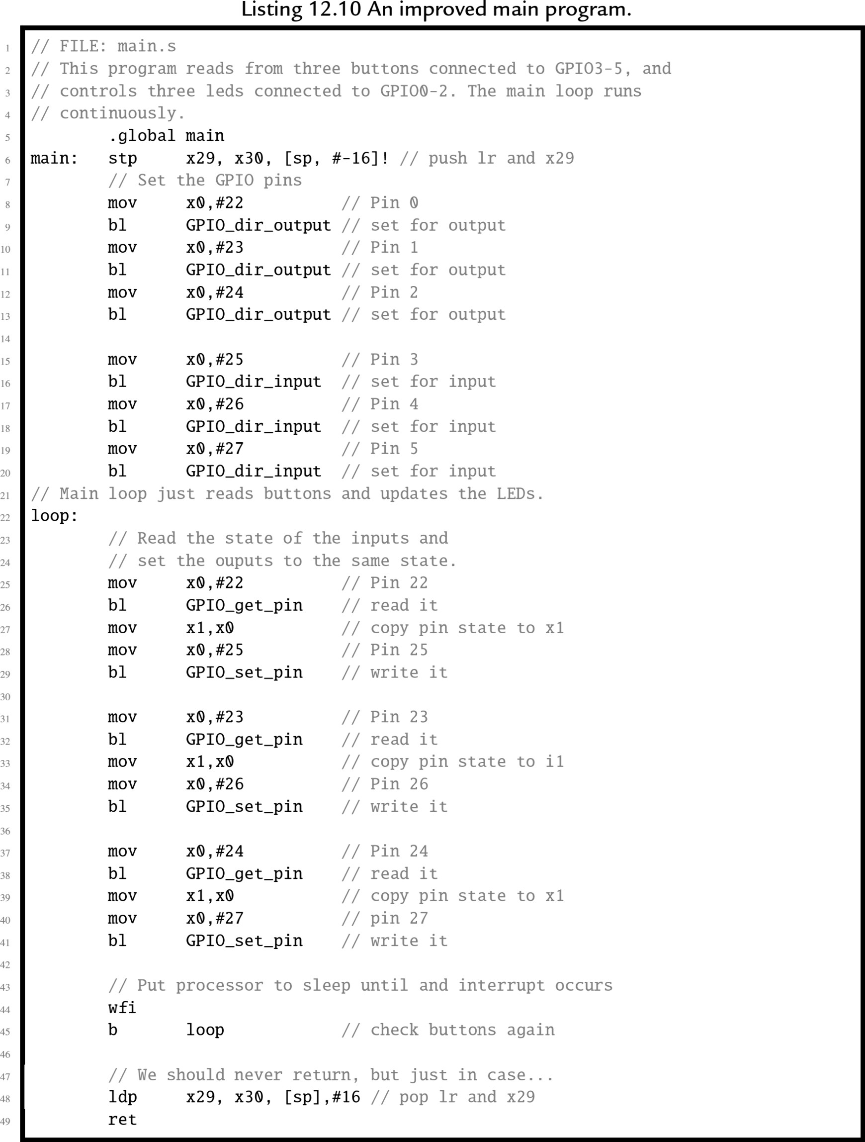
The final part of this bare metal program is the ![]() function. Listing 12.7 shows a very simple main program which reads from three GPIO pins which have push-buttons connected to them, and controls three other pins that have LEDs connected to them. When a button is pressed the LED associated with it is illuminated. The functions to control the GPIO device, which is introduced in Chapter 11, have been removed from the main program file. This makes the main program portable; it can run on any AArch4 system that has a GPIO device, with the addition of another file to implement the functions for using the GPIO device for that system.
function. Listing 12.7 shows a very simple main program which reads from three GPIO pins which have push-buttons connected to them, and controls three other pins that have LEDs connected to them. When a button is pressed the LED associated with it is illuminated. The functions to control the GPIO device, which is introduced in Chapter 11, have been removed from the main program file. This makes the main program portable; it can run on any AArch4 system that has a GPIO device, with the addition of another file to implement the functions for using the GPIO device for that system.
12.5.3 The linker script
When compiling the program, it is necessary to perform a few extra steps to ensure that the program is ready to be loaded and run by the boot code. The last step in compiling a program is to link all of the object files together, possibly also including some object files from system libraries. A linker script is a file that tells the linker which sections to include in the output file, as well as which order to put them in, what type of file is to be produced, and what is to be the address of the first instruction. The default linker script used by GCC creates an ELF executable file, which includes startup code from the C library and also includes information which tells the loader where the various sections reside in memory. The default linker script creates a file that can be loaded by the operating system kernel, but which cannot be executed on bare metal.
For a bare metal program, the linker must be configured to link the program so that the first instruction of the startup function is given the correct address in memory. This address depends on how the boot loader will load and execute the program. On the Raspberry Pi this address is 0x8000. The linker will automatically adjust any other addresses as it links the code together. The most efficient way to accomplish this is by providing a custom linker script to be used instead of the default system script. Additionally, either the linker must be instructed to create a flat binary file, rather than an ELF executable file, or a separate program (objcopy) must be used to convert the ELF executable into a flat binary file.
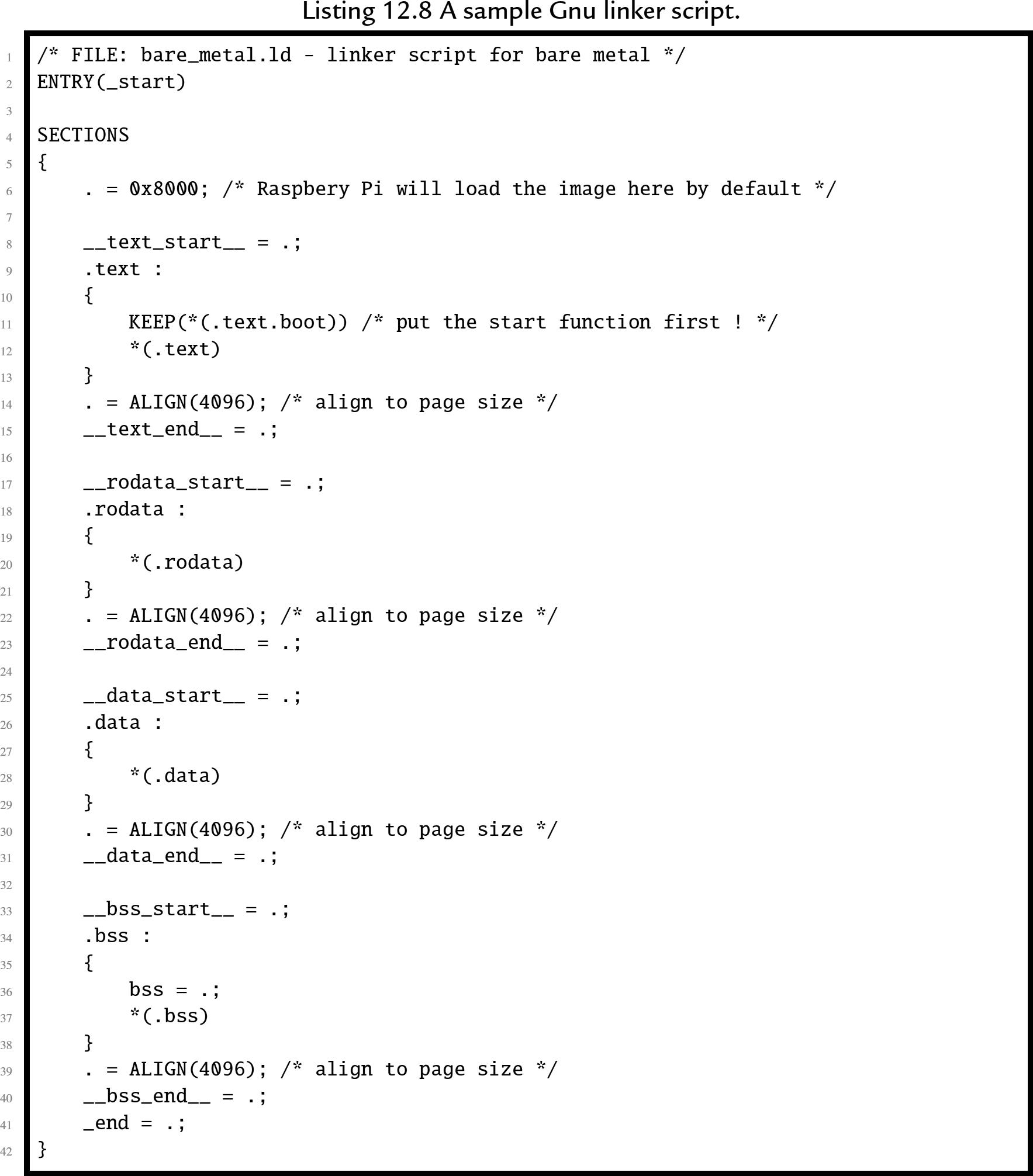
Listing 12.8 is an example of a linker script that can be used to create a bare metal program. The first line is just a comment. The second line specifies the name of the function where the program begins execution. In this case, it specifies that a function named _start is where the program will begin execution. Next, the file specifies the sections that the output file will contain. For each output section, it lists the input sections that are to be used.
The first output section is the .text section, and it is composed of any sections whose names end in .text.boot followed by any sections whose names end in .text. In Listing 12.6, the ![]() function was placed in the .text.boot section, and it is the only thing in that section. Therefore the linker will put the _start function at the very beginning of the program. The remaining text sections will be appended, and then the remaining sections, in the order that they appear. After the sections are concatenated together, the linker will make a pass through the resulting file, correcting the addresses of branch and load instructions as necessary so that the program will execute correctly.
function was placed in the .text.boot section, and it is the only thing in that section. Therefore the linker will put the _start function at the very beginning of the program. The remaining text sections will be appended, and then the remaining sections, in the order that they appear. After the sections are concatenated together, the linker will make a pass through the resulting file, correcting the addresses of branch and load instructions as necessary so that the program will execute correctly.
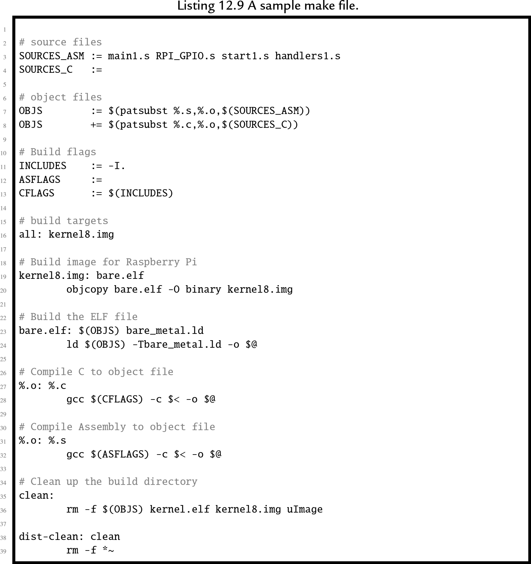
12.5.4 Putting it all together
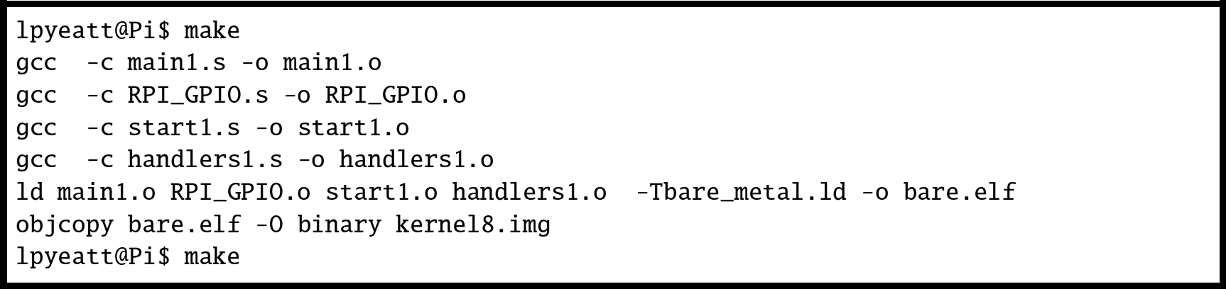
Compiling a program that consists of multiple source files, a custom linker script, and special commands to create an executable image can become tedious. The make utility was created specifically to help in this situation. Listing 12.9 shows a make file that can be used to combine all of the elements of the program and produce a kernel8.img file for the Raspberry Pi. Fig. 12.5 shows how the program can be built by typing “make” at the command line.
12.6 Using an interrupt
The main program shown in Listing 12.7 is extremely wasteful because it runs the CPU in a loop, repeatedly checking the status of the GPIO pins. It uses far more CPU time (and electrical power) than is necessary. In reality, the pins are unlikely to change state very often, and it is sufficient to check them a few times per second. It only takes a few nanoseconds to check the input pins and set the output pins so the CPU only needs to be running for a few nanoseconds at a time, a few times per second.
A much more efficient implementation would set up a timer to send interrupts at a fixed frequency. Then the main loop can check the buttons, set the outputs, and put the CPU to sleep. Listing 12.10 shows the main program, modified to put the processor to sleep after each iteration of the main loop. The only difference between this main function and the one in Listing 12.7 is the addition of a ![]() instruction at line 44. The new implementation will consume far less electrical power and allow the CPU to run cooler, thereby extending its life. However, some additional work must be performed in order to set up the timer and interrupt system before the main function is called.
instruction at line 44. The new implementation will consume far less electrical power and allow the CPU to run cooler, thereby extending its life. However, some additional work must be performed in order to set up the timer and interrupt system before the main function is called.
12.6.1 Startup code with interrupt enabling
Some changes must be made to the startup code in Listing 12.6 so that after setting up the vector table, it calls a function to initialize the interrupt controller then calls another function to set up the timer. In Listing 12.11, lines 111 through 114 have been added to initialize the interrupt controller and enable the timer:

12.6.2 Interrupt controllers
The Raspberry Pi has a relatively simple interrupt controller. It can enable and disable interrupt sources, and requires that the programmer read up to three registers to determine the source of an interrupt. For our purposes, we only need to manage the ARM timer interrupt. Listing 12.12 provides a few basic functions for using this device to enable the timer interrupt. Extending these functions to provide more functionality would not be very difficult, but would take some time. It would be necessary to set up a mapping from the interrupt bits in the interrupt register controller to integer values, so that each interrupt source has a unique identifier. Then the functions could be written to use those identifiers. The result would be a software implementation that is more portable.

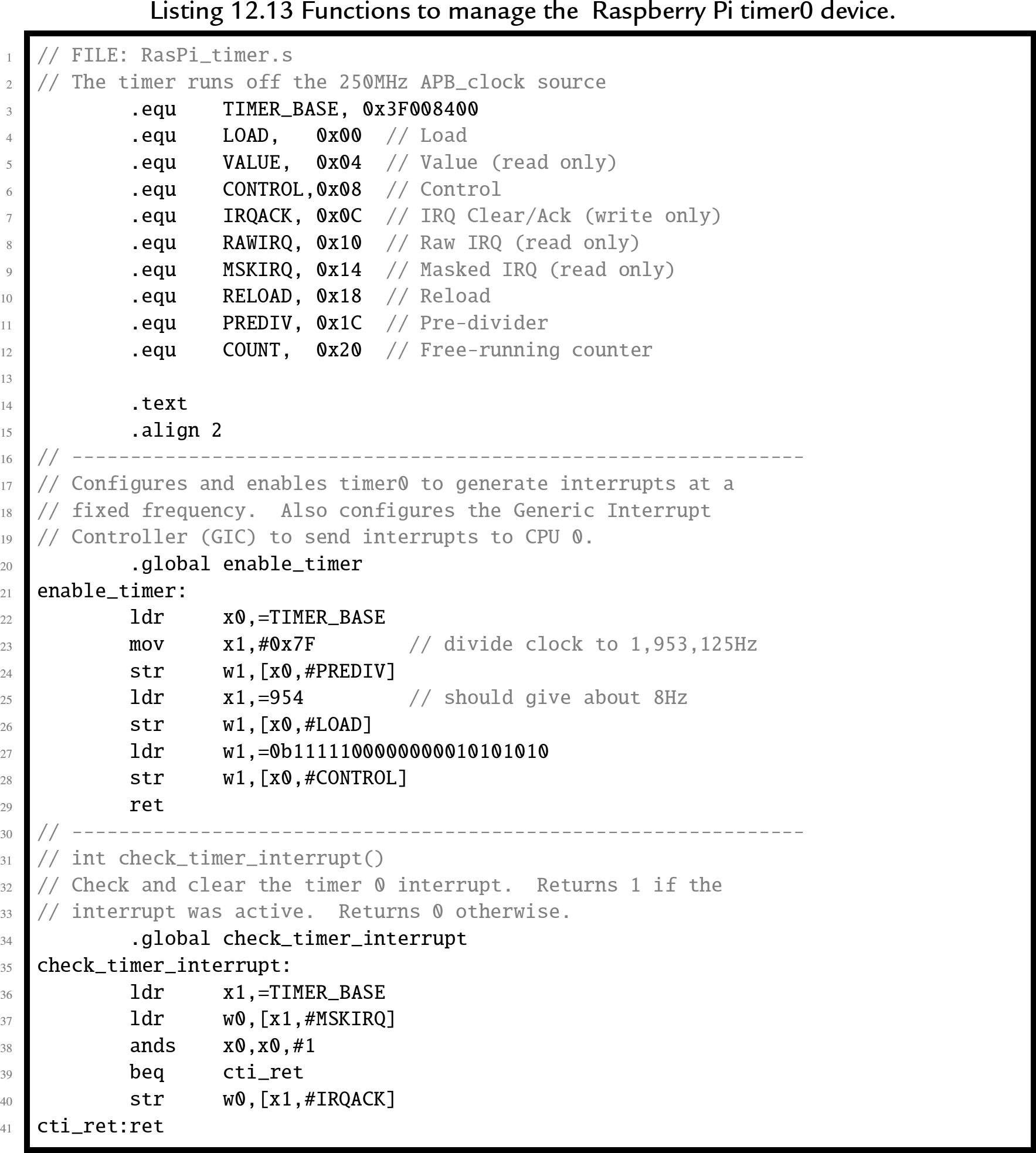
12.6.3 Timers
The Raspberry Pi provides several timers that could be used, but the ARM timer is the easiest to configure. The following listing provides a few basic functions for managing this device:
12.6.4 Exception handling
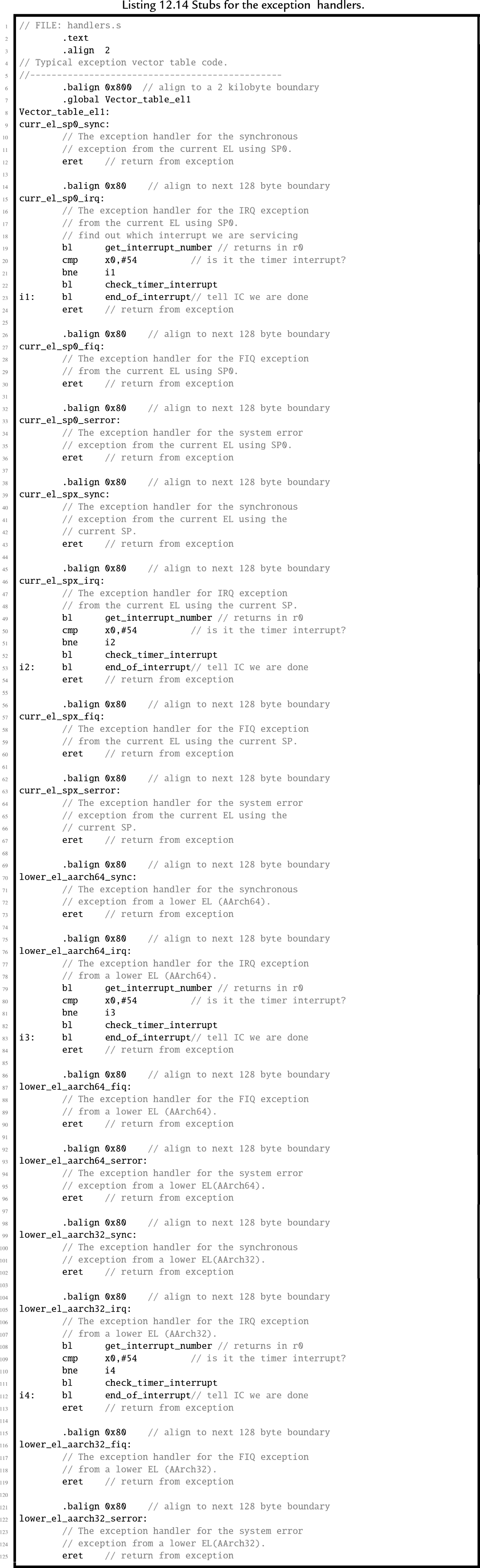
The final step in writing the bare metal code to operate in an interrupt-driven fashion is to modify the IRQ handlers from Listing 12.1 so that the actually does something. Listing 12.14 shows a new version of the IRQ exception handlers which check and clear the timer interrupt, then return to the location and CPU mode that were current when the interrupt occurred.
12.6.5 Building the interrupt-driven program
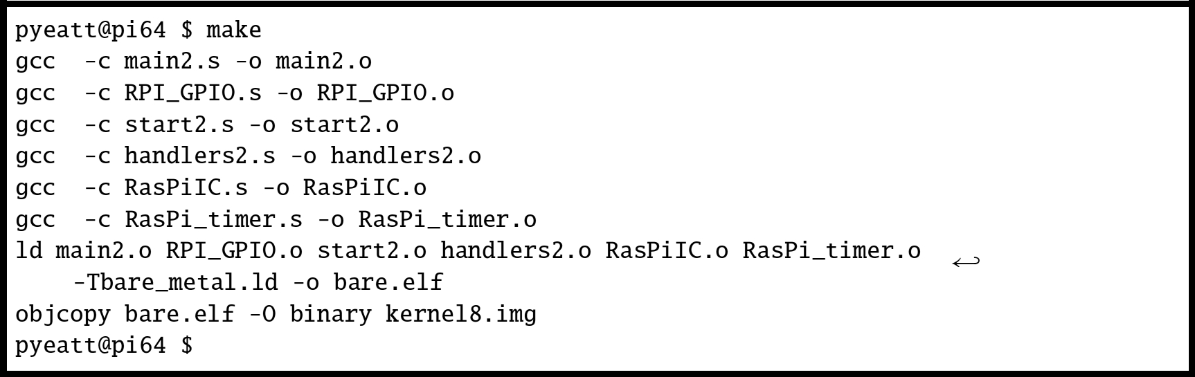
Finally, the make file must be modified to include the new source files that were added to the program. Listing 12.15 shows the modified make file. The only change is that two extra object files have been added, when make is run, those files will be compiled and linked with the program. Fig. 12.6 shows how the program can be built by typing “make” at the command line.

12.7 ARM processor profiles
Since its introduction in 1982 as the flagship processor for Acorn RISC Machine, the ARM processor has gone through many changes. Throughout the years, ARM processors have always maintained a good balance of simplicity, performance, and efficiency. Although originally intended as a desktop processor, the ARM architecture has been more successful than any other architecture for use in embedded applications. That is at least partially because of good choices made by its original designers. The architectural decisions resulted in a processor that provides relatively high computing power with a relatively small number of transistors. That results in relatively low power consumption.
Today, there are almost 20 major versions of the ARMv7 architecture, targeted for everything from smart sensors to desktops and servers, and sales of ARM based processors outnumber all other processor architectures combined. Historically, ARM has given numbers to various versions of the architecture. With the ARMv7, they introduced a simpler scheme to describe different versions of the processor. They divided their processor families into three major profiles:
ARMv7-A Applications processors are capable of running a full, multiuser, virtual memory, multiprocessing operating system.
ARMv7-R: Real-time processors are for embedded systems that may need powerful processors, cache, and/or large amounts of memory.
ARMv7-M: Microcontroller processors only execute Thumb instructions and are intended for use in very small cost-sensitive embedded systems. They provide low cost, low power, and small size, and may not have hardware floating point or other high-performance features.
In 2014, ARM introduced the ARMv8 (AArch64) architecture. This is the first radical change in the ARM architecture in over 30 years. The new architecture extends the register set to thirty 64-bit general purpose registers, and has a completely new instruction set. Compatibility with ARMv7 and earlier code is supported by switching the processor into 32-bit mode, so that it executes the 32-bit ARM instruction set. This is somewhat similar to the way that the Thumb instructions are supported on 32-bit ARM cores, but the change to 32-bit code can only be made when the processor is in privileged mode, and drops back to unprivileged mode.
12.8 Chapter summary
Writing bare-metal programs can be a daunting task. However, that task can be made easier by writing and testing code under an operating system before attempting to run it bare-metal. There are some functions which cannot be tested in this way. In those cases, it is best to keep those functions as simple as possible. Once the program works on bare-metal, extra capabilities can be added.
Interrupt-driven processing is the basis for all modern operating systems. The system timer allows the O/S to take control periodically and select a different process to run on the CPU. Interrupts allow hardware devices to do their jobs independently and signal the CPU when they need service. The ability to restrict user access to devices and certain processor features provides the basis for a secure and robust system.
Exercises
- 12.1. What are the advantages of a CPU which supports user mode and privileged mode over a CPU which does not?
- 12.2. What are the privileged modes supported by the AArch64 architecture?
- 12.3. The interrupt handling mechanism is somewhat complex and requires significant programming effort to use. Why is it preferred over simply having the processor poll I/O devices?
- 12.4. Where does program control transfer to when a hardware interrupt occurs?
- 12.5. What is an
 instruction? What is its use in operating systems? What is the key difference between an instruction and an interrupt?
 - 12.6. Which of the following operations should be allowed only in privileged mode? Briefly explain your decision for each one.
- a. Execute an instruction.
- b. Disable all interrupts.
- c. Read the time-of-day clock.
- d. Receive a packet of data from the network.
- e. Shutdown the computer
- a. Execute an
- 12.7. The programs in this chapter assumed the existence of libraries of functions for controlling the GPIO pins on the Raspberry Pi. The C prototypes for the functions are:
 ,
,  ,
,  , and
, and  . Write these libraries in ARM assembly language for both platforms.
 - 12.8. Write an interrupt-driven program to read characters from the serial port on the Raspberry Pi. The UART can be configured to send an interrupt when a character is received.
- When a character is received through the UART and an interrupt occurs, the character should be echoed by transmitting it back to the sender. The character should also be stored in a buffer. If the character received is newline ( ), or if the buffer becomes full, then the contents of the buffer should be transmitted through the UART. Then, the buffer cleared and prepared to receive more characters.