
Some Fundamentals of RS-232
RS-232 is a serial interface using DB25 or DB9 connectors and, in some cases, RJ45 connectors. RS-232 specifies both the electrical and mechanical interfaces.
RS-232 is an EIA/TIA norm that is equivalent to V.24/V.28 of the CCITT. V.24, however, specifies the mechanical interface and V.28 the electrical. Both (RS-232, V24/V28) define the same interface and will hereafter be referred to as RS-232.
RS-232 defines the cable connecting a DTE (data terminal equipment—intelligent to data) and a DCE (data communication equipment—pass-through device) and specifies the connector. It is a single-ended interface with one lead for every signal and a ground reference.
The DB25 specification, which is officially called RS-232C, is the most common one. There is also RS-232D, which is RS-232 on an RJ45 connector. On an IBM-compatible PC, you will often find a DB9 male for serial connections. This is also RS-232 and is officially called EIA/TIA 574.
According to the specs, the maximum distance is 15 m. With special cabling, distances up to 150 m are possible, but cannot be guaranteed.
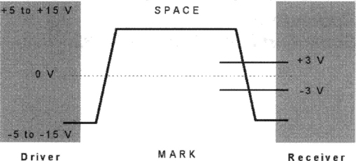
Figure E-1 explains the voltage used in RS-232. A positive voltage between +3 and +15 V represents a logical 0 or space, whereas a negative voltage between -3 and -15 V represents a logical 1 or mark.
The pinout for RS-232 connectors is not unique because of the distinction between DTE and DCE. A personal computer normally is a DTE, whereas a modem is a DCE.
The pinouts for both RS-232 connectors used in PCs are listed in Tables E-1 and E-2.
Table E-3
RS-232 pin assignments (DB25 PC signal set).
| Pin 1 | Protective Ground |
| Pin 2 | Transmit Data |
| Pin 3 | Received Data |
| Pin 4 | Request To Send |
| Pin 5 | Clear To Send |
| Pin 6 | Data Set Ready |
| Pin 7 | Signal Ground |
| Pin 8 | Received Line Signal Detector (Data Carrier Detect) |
| Pin 20 | Data Terminal Ready |
| Pin 22 | Ring Indicator |
The connector on the PC has male pins; therefore, the mating cable needs to be terminated in a DB25/F (female pin) connector.
Table E-2
RS-232 pin assignments (DB9 PC signal set).
| Pin 1 | Received Line Signal Detector (Data Carrier Detect) |
| Pin 2 | Received Data |
| Pin 3 | Transmit Data |
| Pin 4 | Data Terminal Ready |
| Pin 5 | Signal Ground |
| Pin 6 | Data Set Ready |
| Pin 7 | Request To Send |
| Pin 8 | Clear To Send |
| Pin 9 | Ring Indicator |
The connector on the PC has male pins; therefore, the mating cable needs to be terminated in a DB9/F (female pin) connector.
To connect a DTE and a DCE, a straight-through cable (1-1, 2-2, 3-3, etc.) is the most convenient cable to use. If you want to connect two DTEs or two DCEs, you need a null-modem (cross-wired) cable. The distinction between DTE and DCE often leads to confusion.
For a simple data interchange, three wires (Tx, Rx, and GND) are enough. Although the normal PC hardware might well run with just these three wires connected, most driver software will wait forever for one of the handshaking lines to go to the correct level. Depending on the signal state it might work sometimes; other times it might not.
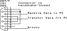
The reliable solution is to loop back the handshake lines, as shown in Figure E-2, if they are not used. When the lines are handshake-looped, the RTS output from the PC immediately activates the CTS input, so the PC effectively controls its own handshaking.
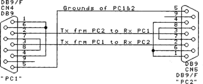
Connecting together two serial devices (DTE) involves connecting the Rx of one device to the Tx of the other, and vice versa. Figure E-3 indicates how you would go about connecting two PCs together, without handshaking.
After the electrical connection is finished, both sides of the communication channel must understand each other.
To prepare data for transmission from one point to another, most RS-232 systems use dedicated communication controllers. These controllers are mostly called UARTs (universal asynchronous receivers and transmitters) and are responsible for controlling the data exchange over the RS-232 interface.
UARTs offload most of the communication activities from the CPU, thus freeing the CPU for other activities. UARTs have the ability to add or remove start and stop bits and provide odd- or even-parity code generation and detection. Currently, components have onboard receiver and transmitter FIFOs for buffering the asynchronous exchanged data.
Figure E-4 shows the structure of the asynchronous transmission protocol used in RS-232 data exchange.
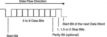
The data transmission starts with a low-level start bit followed by five to eight data bits. An optional parity bit after each character can be generated to check the parity of the received character for error detection on the receiver’s side. The transmission of one character ends with the stop bits. The protocol allows 1, 1.5, or 2 stop bits. After the transmission is completed, the line remains at high level until the start bits of the next character return it to low level.
A further parameter of RS-232 data exchange is the rate of data transmission—the baud rate. The baud rate indicates the number of bits sent or received per second (bps).
A typical configuration for an RS-232 interface in microcontroller applications is shown in Table E-3. With this parameter setup, the transmission time of one character (with 10 bits) is about 1 ms. The parity bit has no function; therefore, no error detection is possible on the receiver’s side.