
5.6. Measurement Studio for Visual C++
Measurement Studio consists of Visual C++ AppWizard of C++ class libraries for measurement applications. Because of their object-oriented nature, class libraries are the intuitive way to deliver functionality to C++ users. By using the Measurement Studio class libraries, you can start and complete your measurement applications quickly. Measurement Studio defines data types that simplify C++ programming for measurement applications and uses these data types across the various class libraries. Furthermore, the Measurement Studio class libraries can work with the Microsoft Foundation Class (MFC) libraries.
Measurement Studio for Visual C++ is a collection of tools designed specifically for engineers and scientists building virtual instrumentation systems using Microsoft's Visual C++ development environment. With integrated C++ libraries for acquiring, analyzing, and displaying data, Measurement Studio for Visual C++ has everything you need for building advanced measurement and automation applications. Whether you are building automated test systems or monitoring applications or laboratory experiments, Measurement Studio for Visual C++ simplifies your development tasks.[*]
[*] Source: National Instruments Corporation. July, 2001. Getting Started with Measurement Studio for Visual C++, pp. 1-2, 1-3. Part no. 323063A-01. Reprinted by permission.
Before you can use the Measurement Studio to develop your test and measurement program in the Visual C++ environment, you have to install the Measurement Studio software on your PC.
5.6.1. Install Measurement Studio
The installation of Measurement Studio requires that you have installed Microsoft Visual Studio 6.0 pack 3 or higher. If the pack version of the Visual Studio 6.0 is less than 3, you need to go to http://msdn.Microsoft.com/vstudio/sp to download the update version. The current update version is pack 5. You only need to download the file vs6sp5.exe, which is 130 MB, and save it to the TEMP folder on your hard drive.
After you finish downloading the vs6sp5.exe file, you first need to create a new folder to unzip this package. In our case, we create a new folder named msvc6sp5 under the root drive, and unzip vs6sp5.exe into that folder.
Click the setupsp5.exe icon when you finish the unzip operation in the msvc6sp5 folder, and begin to update your Visual Studio to the pack 5 version. You don't need to touch your old Visual Studio 6.0 software at all; the setupsp5.exe can handle that job for you automatically. When this updating operation is completed, you can install Measurement Studio.
Insert the Measurement Studio CD into your CD-ROM drive and follow the directions on screen to install Measurement Studio on your computer. The default directory is C:Program FilesNational InstrumentsMeasurement Studio. Generally, you don't need to modify this directory.
Measurement Studio for Visual C++ includes C++ classes, ActiveX controls, and wizards that allow you to build virtual instrumentation and industrial automation applications using Microsoft's Visual C++ development environment. Measurement Studio for Visual C++ takes advantage of COM and ActiveX technologies to deliver a set of integrated development tools and an interactive design approach for developing measurement systems in Visual C++. The Measurement Studio MFC AppWizard helps you design your system by automating the design of your application. Because Measurement Studio for Visual C++ interfaces to measurement hardware, analysis, and user interface components through C++ classes, Measurement Studio for Visual C++ is easy to learn for anyone familiar with Visual C++.
The Measurement Studio for Visual C++ classes are organized into components. The components contain class header files, inline implementation files, and static library files in both Debug and Release versions.
The componentized structure of the Measurement Studio classes provides the benefits listed below.
Minimize the number of Measurement Studio header files that you include in your project.
Allow you to easily add Measurement Studio support to any MFC project.
Allow you to easily add components and drivers to your projects during development.[*]
[*] Source: National Instruments Corporation. July, 2001. Getting Started with Measurement Studio for Visual C++, p. 1-1. Part no. 323063A-01. Reprinted by permission.
5.6.1.1. Measurement & Automation Explorer (MAX)
After installing the Measurement Studio software in your computer, double-click the Measurement & Automation icon, a new icon added to your desktop by the installation software, to open the Measurement & Automation Explorer (MAX) window. A dialog box will prompt you to select the mode to search the hardware installed on your PC. The recommended selection is Every time I launch MAX. In this way, Measurement Studio will automatically check the hardware installed on your PC when you open the MAX window.
MAX provides access to all your National Instruments DAQ, GPIB, IMAQ, IVI, Motion, VISA, and VXI devices. With Measurement & Automation Explorer, you can
configure your National Instruments hardware and software;
add new channels, interfaces, and virtual instruments;
execute system diagnostics; and
view devices and instruments connected to your system.
MAX is an important toolkit in developing your program in the VC++ environment. The first step in your test system development is to install the hardware and the interface cards or boards associated with your actual working environment and target test units. You should use MAX to check, configure, and test your hardware and interface installation, which is the prerequisite for you to develop your testing and measurement systems.
Figure 5-82.

[*]
[*] Source: Screen shot from National Instruments Corporation. Measurement Studio for Visual C++ software. Used by permission.
Your MAX window should look like the one shown in Figure 5-82. The functionality of the icons is described as follows.
Devices and Interfaces: used to help you install devices and interface boards, such as the DAQ boards, VXI, serial interface, GPIB, and computer-based measurement devices. The Devices and Interfaces category lists installed and detected DAQ, GPIB, IMAQ, IVI, Motion, VISA, and VXI hardware and interface boards. You can use this tool to add new DAQ boards, and configure new and existing devices.
Because recently we have not installed any hardware on our PC, only the two serial ports and a parallel port are displayed here.
The IVI Instruments category provides access to the Logical Names wizard and all your IVI logical names. A logical name is a reference to a particular virtual instrument.
The Software category allows you to view, launch, and update your installed National Instruments software.
5.6.2. Using Measurement Studio to Develop a Project in VC++
After you finish installing Measurement Studio, open the Microsoft Visual C++ 6.0 workspace. To create a new project, click File and select New to open the New dialog box, as shown in Figure 5-83.
Figure 5-83.

You will find that a new project type, NI Measurement Studio AppWizard, has been added to this dialog box. Select this type, and type a new project name (msFirst) in the Project name: box, and confirm the path in the Location: box; click OK to move on to the next window.
Select the Measurement MFC Application radio button, and click the Next button to go to the next window. Click the Next button for this window and select Dialog based in the next window. In this way, we selected a dialog box as the GUI in our program. You can select Single/Multiple document for your program. Click the Finish button to create a new project. These steps are very straightforward for programmers used to working in the VC++ environment.
Next, we will use an example to illustrate how to design a test and measurement project using Measurement Studio in the VC++ environment. Because designing and coding a project using Measurement Studio in VC++ is very similar to the process in developing a project in VC++ using VC++ 6.0 MFC, the following discussion will not be very detailed. We assume you are knowledgeable in VC++.
Like any project developed in VC++, first we begin to design a user interface and save this file as a resource file. Open the resource file by clicking the ResourceView tab, and double-click IDD_MSFIRST_DIALOG to open your resource file. From the property tool window, select and add a CWGraph control, a CWKnob control, a CWSlide control, and two Button controls to your dialog panel, as shown in Figure 5-84.
Figure 5-84.

Right-click CWGraph control and select Properties to open its Properties dialog box. Set the properties for the graph control as follows:
General: ID: IDC_CWGRAPH_SINE Caption: SINE WAVEFORM Style: Plots: Colored Plots: Plots: Plot-1; Line Style: solid; Color: Green; Width: 2 Graph: Caption: SINE WAVEFORM; Font: 8; Bold: checked Right-click CWKnob control to open its properties and set:
General: ID: IDC_CWKNOB_AMP Caption: Amplitude Style: 3D Knob Numeric: Maximum: 10; Minimum: 0 Ticks: Label Color: blue Right-click CWSlide control to open its properties window and set:
General: ID: IDC_CWSLIDE1 Caption: LEVEL Style: 3D Thermometer Numeric: Minimum: 0; Maximum: 10 Ticks: Color: brown Right-click Button1 control to open its properties window and set:
General: ID: IDCSTART Caption: START Style: Default Right-click Button2 control to open its properties window and set:
General: ID: IDCSTOP Caption: STOP Style: Default
Next, we will create member variables and member functions using ClassWizard. To connect the graphic controls in your user interface to your program, we need to create the member variables and member functions to respond to the events created by activating the graphic controls as your program runs.
While still in your user interface, right-click the CWGraph control and select ClassWizard to open the MFC ClassWizard dialog box. Set the member variable for this control as follows:
Select IDC_CWGRAPH_SINE in the Control IDs list box, and click the Add Variable button to open the Add Member Variable dialog box. Enter sinegraph after the prefix m_ in the Member variable name input box as the variable's name. The name for this graph is m_sinegraph.
Follow the same steps to create variables for CWKnob and CWSlide controls and assign the variables' names as follows:
| ID | Variable Name |
|---|---|
| IDC_CWKNOB_AMP | m_ampknob |
| IDC_CWSLIDE1 | m_slide |
While still inside the ClassWizard window, create the member functions. Click the Message maps tab, and select IDC_CWKNOB_AMP control ID. Select the PointerValueChanged in the Messages list box and click the Add function button to open the Add Member Function dialog box. The function name has been defined; you only click OK to save it.
Keep the Message maps tab selected, and select IDCSTART control ID. Then click BN_CLICKED in the Messages list box, and click the Add Function button to create a new function, OnStart(), for this button. Click OK to close the Add Member Function dialog box. Do the same thing to add a new OnStop() function for the IDCSTOP control.
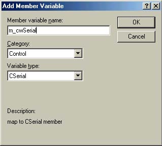
Now, we begin to code the program. Add a member variable to the class CMsFirstDlg class. Click the ClassView tab in the workspace, find the class CMsFirstDlg, right-click this class, and select Add Member Variable. In the resulting dialog box, enter CNiReal64Vector as the variable type, and enter m_wave as the variable name. Select Private in Access. We will use this variable to hold the sine wave data. CNiReal64Vector is a Measurement Studio data type that holds an array of double values. Click OK to close this dialog box.
Open the msFirstDlg.cpp source file, and find the BOOL CMsFirstDlg:: OnInitDialog() function. This is the initialization function to initialize the variables for your dialog box on the user interface panel we developed previously. You should place all initialization codes in this function because this function will be called first as your program runs. Add the highlighted code shown in Figure 5-85 into this function.
Figure 5-85.
BOOL CMsFirstDlg::OnInitDialog() { CDialog::OnInitDialog(); //Add "About..." menu item to system menu. //IDM_ABOUTBOX must be in the system command range. ASSERT((IDM_ABOUTBOX & 0xFFF0) == IDM_ABOUTBOX); ASSERT(IDM_ABOUTBOX < 0xF000); CMenu*pSysMenu = GetSystemMenu(FALSE); if (pSysMenu != NULL) { CString strAboutMenu; strAboutMenu.LoadString(IDS_ABOUTBOX); if (!strAboutMenu.IsEmpty()) { pSysMenu->AppendMenu(MF_SEPARATOR); pSysMenu->AppendMenu(MF_STRING,IDM_ABOUTBOX, strAboutMenu); } } //Set the icon for this dialog. The framework does this automatically //when the application's main window is not a dialog SetIcon(m_hIcon, TRUE); //Set big icon SetIcon(m_hIcon, FALSE); //Set small icon //TODO:Add extra initialization here m_ampknob.Value = 1; return TRUE; // return TRUE unless you set the focus to a control } |
Add the code shown in Figure 5-86 into the OnStart() member function, which is activated by clicking the Start button as your program runs. When you click the Start button on your dialog box panel, the CNiMath function will be called to create a sine waveform, and this waveform will be saved into the array m_wave. m_sinegraph is called to plot this waveform on the CWGraph control on your user interface.
Figure 5-86.
void CMsFirstDlg::OnStart() { // TODO: Add your control notification handler code here CNiMath::SineWave (m_wave, 100, 2); m_sinegraph.Plots.Item(1).PlotY(m_wave); } |
Add the code shown in Figure 5-87 to the OnStop() member function. When you click the Stop button, exit(0) will be executed to terminate your program.
Figure 5-87.
void CMsFirstDlg::OnStop() { // TODO: Add your control notification handler code here exit(0); } |
Add the code shown in Figure 5-88 into the OnPointerValueChangedCwknobAmp() function. The purpose of this function is to receive an event coming from the knob in the user interface to indicate that the value pointed by the knob has been changed by the user, and the changed value is also passed to this function by the address of that parameter, *Value, with a VARIANT Measurement Studio data type. The CNiVariant() function is used to convert this parameter into a value with a double data type, and the latter is used as a parameter to be passed to the member function, SetValue(), to set the level of the thermometer that represents the level of the sine data.
Figure 5-88.
void CMsFirstDlg::OnPointerValueChangedCwknobAmp(long Pointer, VARIANT FAR* Value) { // TODO: Add your control notification handler code here CNiReal64Vector sine_data(m_wave); sine_data.Scale(CNiVariant(Value)); m_sinegraph.Plots.Item(1).PlotY(sine_data); m_slide.GetPointers().Item(1).SetValue(CNiVariant(Value)); // m_slide.GetPointers().Item(1).SetValue(m_ampknob.GetValue()); } |
CNiReal64Vector sine_data(m_wave); is used to create a local vector for the sine data array. It is followed by a function to scale the value of the array to the voltage. m_sinegraph.Plots.Item(1).PlotY(sine_data); is used to plot this modified sine waveform. m_slide.GetPointers().Item(1).SetValue(CNiVariant(Value)); is used to update the data. Different object layers are involved in the last two statements, and SetValue() is the member function that belongs the last object layer.
Compile and build your project by clicking Build and select Build msFirst.exe to obtain your executable file. Run your project by clicking Build and select Execute msFirst.exe. Your running program should look like the one shown in Figure 5-89.
Figure 5-89.
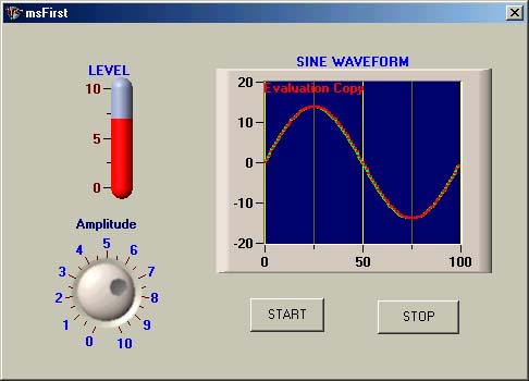
As your program runs, click the START button to begin to display a sine wave-form on the graph control in your user interface. When you rotate the knob to change the amplitude of the sine waveform, both the waveform displayed on the graph and the level of the slider will be changed accordingly. Click STOP to terminate your program.
5.6.3. A Real Example Using a Serial Driver
In this section, we want to implement a real project that is developed using an NI serial driver to illustrate the complete development process for a real test and measurement project using Measurement Studio package.
Figure 5-90 shows the functionality of this project in block diagram. This project first creates two threads after the initialization. One is the Write thread and the other is the Read thread. The Write thread is used to write a sine data generated from a CNiMath object to the serial port, and the Read thread is used to display the data received from the same serial port. The serial port used here is COM1. Figure 5-91 shows the function block diagram for this project.
Figure 5-90.

Figure 5-91.
5.6.3.1. Serial Port Installation and Testing
Shut down your computer and install a DB-9 serial connector as shown in Figure 5-92. The definition of the pins on DB-9 is also shown in Figure 5-92. A loop-back test is used for this project, which means that the pin-2 and pin-3 of a DB-9 serial terminal connector are connected together. In this way, the data sent out will be received back by the buffer of COM1 if the port is working properly.
Figure 5-92.

Before developing the program, serial port testing is needed to confirm the correct installation of the hardware and the functionality of the serial driver using MAX. Double click the MAX icon on the desktop to open it. The opened MAX window is shown in Figure 5-93. Click the Devices and Interfaces icon and click Ports; all ports (serial and parallel ports) currently installed on your computer will be displayed. Here we have three ports. In this project, COM1 is used as a serial port for the test.
Figure 5-93.

To set up the communication parameters and test COM1, right-click the COM1 icon. In a pop-up menu, select Open VISA Session. In the resulting dialog box, select the viSetAttribute tab, as shown in Figure 5-94.
Figure 5-94.

Enter any data to the New Value textbox as a testing data (5 here), and click the Execute button to test sending this data to COM1. If the data is successfully sent to COM1, it will be displayed in the Current Value textbox, and the Return Value should be 0, which means no error occurred.
Click the viGetAttribute tab to test the receiving data, then click the Execute button on that subwindow. A value of 5 should be displayed in the Current Value textbox and the Return Value should remain 0 if the receiving test is passed.
There are some other test functionalities in this MAX, but for our purposes, these two tests are good enough. If both sending and receiving tests are successful, our hardware installation and serial driver are ready to be used for our project.
If you encounter some problems, possibly either the port is being used by another device or the driver for that port is not properly installed. You need to open the help file to debug the problems and solve them before you can start your project.
Open the MS Visual C++ 6.0 workspace, and click New to create a new project. Select NI Measurement Studio AppWizard in the Project dialog box, enter the project name Serial, and click OK to open the next dialog box.
Make the following selections for the next sequence of dialog boxes:
| Step1: | Measurement MFC Application | click Next |
| Step2: | click Next | |
| Step3: | Dialog-based | click Finish |
Click OK for the New Project Information dialog box to open a new project. Delete the label TODO:Place dialog controls here in the opened dialog box by right-clicking the mouse and selecting cut.
5.6.3.2. Design the User Interface
For familiarity, our project is dialog-box based, which means that this dialog box will work as a view or a window to interface between the operator and the computer. We will add some useful objects or controls to this dialog box in the following steps.
1. | Add a CWGraph control as a graph control. We need to add a CWGraph control to the dialog panel to display the sine waveform, which is generated by calling the CniMath::SineWave() function. This sine waveform will be digitalized and sent to COM1. Open the Resource window by clicking the Resource tab in the workspace, and select the CWGraph control from the Controls toolbox panel. Drag this CWGraph onto the dialog panel and size it to the desired size. Right-click this icon and click the properties item to set the following properties for this CWGraph control:
| ||||||||||||||||||||||
2. | Add two CWNumEdit controls as textbox controls. Select the CWNumEdit control from the toolbox panel, and drag it onto the dialog panel. Right-click it and select the Properties item to open its properties dialog box and set the following properties:
Place a label before this CWNumEdit control, and set the caption of this label as COM Port. In the same way, add another CWNumEdit control and set similar properties for this second CWNumEdit control. The only differences are
The Value property is used to display the default value in these two textboxes when your program runs. | ||||||||||||||||||||||
3. | Add a CWSlider control as an indicator control. Select the CWSlider control from the toolbox and drag it onto the dialog panel. Set the properties as follows:
| ||||||||||||||||||||||
4. | Add two Edit box controls as the indicators for the data sent out and read back. Add two Edit textboxes onto the dialog panel, and set the properties for the first textbox as follows:
Set the properties for the second textbox as:
Place two labels for these two textboxes as Writing Data and Reading Data, respectively. | ||||||||||||||||||||||
5. | Add five CWButton controls as the command buttons. Select CWButton control and drag it onto the dialog panel. Set the properties for the first CWButton as follows:
Add four more CWButton controls, and set properties for each one as follows: CWBUTTON 2:
CWBUTTON 3:
CWBUTTON 4:
CWBUTTON 5:
| ||||||||||||||||||||||
6. | Add an ActiveX control, CWSerial, which will access the serial driver to communicate with the serial port COM1. An ActiveX control of serial control, CWSerial, is provided by NI as the serial driver, and this ActiveX control can be inserted into our project to work as a driver to access COM1. In order to insert this ActiveX control into our project, perform the following steps:
|

Your finished user interface should look like the one shown in Figure 5-97.
Figure 5-97.

| Controls ID | Type | Variable |
|---|---|---|
| IDC_EDIT_WRITE | CEdit | m_showWrite |
| IDC_EDIT_READ | CEdit | m_showRead |
| IDC_GRAPH1 | CNiGraph | m_graph |
| IDC_EDIT_COM | CNiNumEdit | m_comPort |
| IDC_EDIT_BAUD | CNiNumEdit | m_baudRate |
| IDC_CWSLIDE_READ | CNiSlide | m_readSlider |
| IDC_CWSERIAL | CWSerial | m_cwSerial |
5.6.3.3. Create Member Variables and Functions for the Controls on the GUI
After you have finished designing the user interface, you need to make the connection between the controls on the user interface and the functions that will respond to the events created by the controls when the user activates these controls on the user interface as your program runs.
1. | Create the member variables. Create the variables for the controls based on the control IDs shown in Table 5-1.
The last variable was created before when the ActiveX control was inserted into the project. These variables can work as objects and to call their methods to fulfill the functionality when the program runs. | ||||||||||||||||||
2. | Create the member functions. Create the functions shown in Table 5-2 to respond to the events created by the controls on the user interface when these controls are activated by the user. |
5.6.3.4. Add Member Variables and Functions for the Source Code
1. | Add member variables to the project. When the project runs, some member variables and functions are needed to handle specific tasks, and these member variables and functions are different than the member variables and functions defined earlier. The latter are used for communication with the controls on the user interface. To add the member variables to the SerialDlg class, right-click the class SerialDlg on the ClassView window, and select Add Member Variables to open the Add Member Variable dialog box. Enter the variable type on the Variable Type textbox and enter the variable name on the Variable Name textbox. Keep the Public radio button selected, and click OK to finish this addition. An example of adding a variable, rs_data, is shown in Figure 5-98. Figure 5-98.
Add the variables shown in Table 5-3 to the Public section on the SerialDlg class.
| ||||||||||||||||||||||||||||
2. | Add member functions to the project. Currently no member function is used. | ||||||||||||||||||||||||||||
3. | Add non-member variables and functions to the project.
Add the non-member variables shown in Table 5-4 to a newly created header file, user.h. These variables should be declared in this new user.h in this project.
The argument of the thread function is an empty pointer (*void), which can be cast to any data type (see Table 5-5). We use this void pointer to pass the current class's address (this – SerialDlg) to the thread function. Thus the function can access any member variable and member function defined in the current class (SerialDlg). | ||||||||||||||||||||||||||||
4. | Add a timer to the project. Convenient for the user, a timer can respond to some event periodically when your program runs. To add a timer to the project perform the following steps.
|

As you recall, we added this timer event function as a member function into the SerialDlg class in the previous section. This function body will be defined in the SerialDlg.cpp file later.
5.6.3.5. Create the Source Code for the Project
We need to add the detail function body to the project, or rather, we need to add all source code to the SerialDlg.cpp file: initialization code, thread function code, and event function codes. First, we need to add the code in the initialization section to the SerialDlg.cpp file.
A block diagram of the initialization sequence is shown in Figure 5-99. Add the initialization code under the BOOL CSerialDlg::OnInitDialog() function on the SerialDlg.cpp file. Open the SerialDlg.cpp file and type the highlighted code shown in Figure 5-100 under the BOOL CSerialDlg::OnInitDialog() function.
Initialize both confgFlag and bStopThread flag signals as false.
Create three events, ExitEvent, WriteEvent, and ReadEvent, using the CreateEvent function. The prototype of this function is
CreateEvent(LPSECURITY_ATTRIBUTES lpEventAttributes,
                 BOOL bManualReset,
                 BOOL bInitialState,
                    LPCTSTR lpName
                          );
Figure 5-99.

Figure 5-100.
BOOL CSerialDlg::OnInitDialog() { CDialog::OnInitDialog(); //Add "About..." menu item to system menu. //IDM_ABOUTBOX must be in the system command range. ASSERT((IDM_ABOUTBOX &0xFFF0) == IDM_ABOUTBOX); ASSERT(IDM_ABOUTBOX < 0xF000); CMenu*pSysMenu = GetSystemMenu(FALSE); if (pSysMenu != NULL) { CString strAboutMenu; strAboutMenu.LoadString(IDS_ABOUTBOX); if (!strAboutMenu.IsEmpty()) { pSysMenu->AppendMenu(MF_SEPARATOR); pSysMenu->AppendMenu(MF_STRING, IDM_ABOUTBOX, strAboutMenu); } } // Set the icon for this dialog.The framework does this automatically // when the application's main window is not a dialog SetIcon(m_hIcon, TRUE); // Set big icon SetIcon(m_hIcon, FALSE); // Set small icon // TODO: Add extra initialization here confgFlag = false; bStopThread = false; hExitEvent = CreateEvent(NULL, TRUE, FALSE, NULL); hWriteEvent = CreateEvent(NULL, TRUE, FALSE, NULL); hReadEvent = CreateEvent(NULL, TRUE, FALSE, NULL); CNiMath::SineWave (x, 500, 10); for (int i = 0; i < 500; i++) weData [i ] = x[i]; ReadThread = AfxBeginThread(ThreadFuncRead, this); WriteThread = AfxBeginThread(ThreadFuncWrite, this); if (ReadThread == NULL || WriteThread == NULL) { AfxMessageBox("Eooror in Creating Thread!"); AfxAbort(); } return TRUE; // return TRUE unless you set the focus to a control } |
The first argument is a pointer to the SECURITY_ATTRIBUTES. A NULL is used here, which means that this event handle cannot be inherited. The second parameter is a Boolean variable, which indicates whether this event can be reset automatically by the program or manually by the user. If this variable is True, you have to use the ResetEvent() function to reset this event after it is activated. Otherwise, the computer will reset it automatically after it is signaled. The third parameter is the initial status of this event after it is created. True means that this event is signaled. In our case, we keep it unsignaled after it is created. The fourth parameter is the name of the event, and a NULL means there is no name for this event.
Create a sine waveform that will be sent to the serial port. Using
CNiMath::SineWave (x, 500, 10);
 for (int i = 0; i < 500; i++)
          weData[i] = x[i];
to create a sine waveform with 500 data points and an amplitude of 10. Assign this waveform to the x vector. The for loop is used to assign the data in the x vector to a data array, weData[], which is a double data array.
Create ReadThread and WriteThread and begin to run the thread functions.
 ReadThread = AfxBeginThread(ThreadFuncRead, this);
WriteThread = AfxBeginThread(ThreadFuncWrite, this);
Use AfxBeginThread() to create two threads, and pass a pointer, this, which is the current class SerialDlg, to the thread function because later on the thread function will use some member variables defined in that class to display the data received from the serial port on the edit box.
Next, we address the thread function code. Add the code shown in Figure 5-101 to the thread function, ThreadFuncWrite(), which is defined in the SerialDlg.cpp file.
Figure 5-101.
UINT ThreadFuncWrite(LPVOID pParam) { HANDLE hEvents[] ={hExitEvent, hWriteEvent}; DWORD Ret; COleVariant vText; CString wData; int n = 0; CSerialDlg* cDlg = (CSerialDlg*)pParam; while(1) { Ret = WaitForMultipleObjects(channel, hEvents, FALSE, INFINITE); if (Ret == WAIT_OBJECT_0 ) //terminate event is received { ResetEvent(hExitEvent); break; } else //write event is received { ResetEvent(hWriteEvent); while(!(cDlg->bStopThread)) { wData.Format("%d 13", (int)(cDlg->weData[n])); cDlg->m_showWrite.SetWindowText(wData); n++; if (n > 500) n = 0; vText= wData; cDlg->m_cwSerial.Write(vText);//write data to serial port Sleep(1); } } break; } Sleep(10); return 0; } |
First, create some local variables as shown in Figure 5-102.
Figure 5-102.
									HANDLE hEvents[]={hExitEvent, hWriteEvent};
									DWORD       Ret;
									COleVariant vText;
									CString     wData;
									int         n = 0;
The handle array, hEvents[], is created by combining two event handles, hExitEvent and hWriteEvent, in an array. Because we need to monitor both the Write event and the Exit event as the thread runs, we use a WaitFor MultipleObjects() function to perform this job. That function needs the event handle in an array format. Ret is a double word used to receive the return status of calling the WaitForMultipleObjects() function. vText is an OLE data type defined in Microsoft and is used to store the data to be sent to the COM1 port. Integer n is used to indicate the index of the sine data array.
Use a cast, CSerialDlg*, to convert the void pointer passed to the thread function to the current user interface class, SerialDlg, as follows:
CSerialDlg* cDlg = (CSerialDlg* )pParam;
In this way, we obtain a pointer, cDlg, which points to the current user interface class, SerialDlg.
Following this code, an infinite loop, while(1), is used to continuously run the thread function until an event happens, either the Exit event or the Write event. The code is shown in Figure 5-103.
Figure 5-103.
									while(1)
									{
									Ret = WaitForMultipleObjects(channel, hEvents, FALSE, INFINITE);
									if (Ret == WAIT_OBJECT_0 )         //terminate event is received
									{
									ResetEvent(hExitEvent);
									break;
									}
									else
									{
									…….
The prototype of the WaitForMultipleObjects() function is
         DWORD WaitForMultipleObjects(
   DWORD nCount, //number of handles in array
 CONST HANDLE *lpHandles, //object-handle array
          BOOL fWaitAll, //wait option
    DWORD dwMilliseconds //time-out interval
                      );
fWaitAll is a Boolean variable used to indicate whether this function should return when one of the events is signaled or all events are signaled. True means that this function returns when all events are signaled, and false means that if any event is signaled, the function will return. dwMilliseconds is the timeout setup value in ms.
Following the WaitForMultipleObjects() function, we check which event is signaled when this function returns. If the function returns as an Exit event is signaled, the returned value should be WAIT_OBJECT_0. In this case, we call the ResetEvent() function to reset the Exit event and break out of the while(1) loop to terminate the thread function.
If the function returns WAIT_OBJECT_1, it means that a Write event is signaled, as shown in Figure 5-104.
Figure 5-104.
									else                                         //write event is received
									{
									ResetEvent(hWriteEvent);
									while(!(cDlg->bStopThread))
									{
									wData.Format("%d 13", (int)(cDlg->weData[n]));
									cDlg->m_showWrite.SetWindowText(wData);
									n++;
									if (n > 500)
									n = 0;
									vText= wData;
									cDlg->m_cwSerial.Write(vText);  //write data to serial port
									Sleep(1);
									}
									}
In this case, we first reset the Write event by calling the ResetEvent(), and then begin another infinite loop to send the sine data to the COM1 port. We use a Format method, which belongs to the wData, a CString object, to convert the sine data to a character followed by a CR key, and use the object of the CEdit control, m_showWrite, to call its method SetWindowText() to display this sending data on this edit box. Also, we call the ActiveX control, m_cwSerial, to send this data to the COM1 port by calling its method Write(). We call the Sleep(1) function to snap 1 ms and go to the next loop until the bStopThread flag is signaled. In that case, we exit the infinite loop and terminate the thread.
The completed code for the ThreadFuncWrite() function is shown in Figure 5-101.
Add the following code to the thread function, ThreadFuncRead(), which is defined in the SerialDlg.cpp file, as shown in Figure 5-105.
Figure 5-105.
UINT ThreadFuncRead(LPVOID pParam) { HANDLE hEvents[] = { hExitEvent, hReadEvent }; DWORD Ret; CString rData; int n = 0; CSerialDlg*cDlg = (CSerialDlg*)pParam; while(1) { Ret = WaitForMultipleObjects(channel, hEvents, FALSE, INFINITE); if (Ret == WAIT_OBJECT_0 ) //terminate event is received { ResetEvent(hExitEvent); break; } else //read event is received { ResetEvent(hReadEvent); while(!(cDlg->bStopThread)) { rData.Format("%d13", (int)(cDlg->reData[n])); cDlg->m_showRead.SetWindowText(rData); n++; if (n > 500) n = 0; Sleep(1); } } break; } Sleep(10); return 0; } |
First, create the same local variables as we did in the Write thread function.
Similarly, use cast CSerialDlg* to convert the void pointer to the address of the current user interface class, SerialDlg.
Call the WaitForMultipleObjects() function to wait for any event occurrence. Reset the Exit event and terminate the thread if the Exit event is signaled. Otherwise, begin another infinite loop to display the read-back data on the edit box as shown in Figure 5-106.
rData is an object of CString class. The Format method of that class is called to convert the sine data, reData[n], from the double to character, then the method of the CEdit class, SetWindowText(), is called to display this character on the edit box. This display will continue to the next data until the Stop flag is signaled. In that case, the while() loop will be stopped and the thread will be terminated.
Figure 5-106.
else //read event is received { ResetEvent(hReadEvent); while(!(cDlg->bStopThread)) { rData.Format("%d 13", (int)(cDlg->reData[n])); cDlg->m_showRead.SetWindowText(rData); n++; if (n > 500) n = 0; Sleep(1); } } |
Lastly, we look at the event function codes.
Configure Event Function.
When you click the Configure button on the user interface, a configure event is created and it will be passed to this Configure Event Function. We added the event function OnConfg() in the previous section when we created the member functions.
The function body is defined as shown in Figure 5-107. A method of the ActiveX control, SetComPort(), is called to set the COM port based on the number entered by the user in the CWNumEdit control box. The m_comPort is an object of CWNumEdit control, and this object uses a method, GetText(), to retrieve the number entered by the user. The atoi() function is used to convert this string to a integer and send it to the COM port.
Figure 5-107.
									void CSerialDlg::OnConfg()
									{
									m_cwSerial.SetComPort (atoi(m_comPort.GetText()));
									m_cwSerial.SetBaudRate (atoi(m_baudRate.GetText()));
									m_cwSerial.Configure();
									confgFlag = true;
									}
Similarly, the SetBaudRate() method is called to set up the baud rate based on the baud rate entered by the user. Finally, the CWSerial ActiveX control calls its method, Configure(), to configure the COM port. The confgFlag flag is set to true after the configuration and to inform all other functions that the configuration has been completed.
Write Data Event Function.
When the user clicks the Write button, a Write event is created and passed to the event function OnWrite(), which we added in the previous section. The definition of this event function is shown in Figure 5-108.
Figure 5-108.
									void CSerialDlg::OnWrite()
									{
									if (!confgFlag)
									{
									AfxMessageBox("The Port Has Not been Configured !");
									return;
									SetEvent(hWriteEvent);
									}
First, we check whether the COM port has been configured by checking the confgFlag flag. If it has been configured, the Write event is signaled to inform the Write thread to begin the writing data process. Otherwise, a warning message is displayed to ask the user to configure the COM port first.
Read Data Event Function.

A little complicated structure has been applied to the read event function. The read method provided by the CWSerial ActiveX control, Read(), can read one data vector at a time, and the data vector returned is in COleVariant format. The additional job we need to do is to convert this vector from the COleVariant format to a normal character array. This step is necessary because later on in the read thread function, that normal character array is required to display the read-back data on the edit textbox one by one. The member function, OnRead(), is defined in Figure 5-109.
Figure 5-109.
									void CSerialDlg::OnRead()
									{
									char*  token;
									char   seps[] == "13";
									int    n = 0;
									if (!confgFlag)
									{
									AfxMessageBox("The Port Has Not been Configured !");
									return;
									}
									SetEvent(hReadEvent);
									sTimer->Start();
									rs_data = m_cwSerial.Read(COleVariant((short)500));
									rdData = rs_data.bstrVal;
									LPTSTR lpsz = new CHAR [ rdData..GetLength()+1];
									_tcscpy(lpsz, rdData);
									token = strtok(lpsz,seps);
									while(token != NULL )
									{
									/*While there are tokens in "string"*/
									reData [n ] == atof(token);
									/*Get next token:*/
									token = strtok(NULL,seps);
									n++;
									if (n > = 500)
									break;
									}
									delete lpsz;
									}
Some local variables are created, such as a character pointer token, a separation keyword CR, and cycle variable n. Like the Write event function, first we need to check whether the port has been configured. If not, a warning message will appear and exit the function. If the configuration has been performed, a Read event is sent to the read thread function to begin the function. In here, we want to start the timer we added in the previous section to create a tick event in the project to do some job periodically.
Of course, you can start this timer at any section in your program to monitor or check some objects as your program runs. The member variable sTimer is a pointer to a timer object, which was created by using the new keyword inside the Serial.cpp file in the previous section. A method of the timer, Start(), is called by sTimer to start the timer.
A method of the ActiveX control CWSerial, Read(), is called to read a set of data (500 here) from the COM1 port. The argument for this method is a type of COleVariant array. The returned array type is a CNiVariant, which is defined in the Measurement Studio library. A method of CNiVariant class, bstrVal is used to convert the data array to an array of string, and the latter is assigned to a string object, rdData.

The following codes are used to separate each character from the string obtained above, because we want to display these characters one by one in the edit box, m_showRead, which was added in the previous section. Each separated character is then converted into a double variable and assigned to a double array reData[], one by one. The reData[] is a member variable array that was added in the previous section. One point you need to know is that the CString object is a string defined in C++, and this kind of string does not attach a NULL at the end of the string as the termination mark of the string. In the ordinary character string defined in C, a NULL is attached at the tail of the string as the ending mark. So in order to convert a CString in C++ to a double array, we first need to translate the CString to a normal string in C. Here a temporary normal string, lpsz, is used. But before you copy the CString to lpsz, you need to assign the memory space for this normal string. The size of the memory should be equal to the size of the CString plus one, because lpsz needs one more space to attach the NULL at the end of the string.
Don't forget to clean the space assigned for this temporary string by using delete when this string is no longer to be used.
Display Event Function.
This function is very simple. When the user clicks the Display button on the user interface, an event is created and passed to this event function. The task of this function is to draw the sine waveform to be sent to the COM1 port on the CNiGraph control, m_graph. The source code for this function, OnDisplay(), is shown in Figure 5-110.
Figure 5-110.
									void CSerialDlg::OnDisplay()
									{
									//TODO:Add your control notification handler code here
									m_graph.Plots.Item(1).PlotY(x);
									}
The PlotY() method of the CNiGraph control is called to draw the sine waveform on the m_graph object. The data is stored in the x vector, which has a CNiReal64Vector format.
Stop Event Function.
This event function will be called when the user clicks the Stop button. The function body is defined in Figure 5-111.
Figure 5-111.
									void CSerialDlg::OnStop()
									{
									HANDLE hThread[]={ ReadThread, WriteThread };
									bStopThread = true;
									SetEvent(hExitEvent);
									Sleep(10);
									WaitForMultipleObjects(channel, hThread, TRUE, INFINITE);
									ResetEvent(hExitEvent);
									CloseHandle(ReadThread);
									CloseHandle(WriteThread);
									CDialog::OnOK();
									}
In order to safely terminate the program, we need to make sure that all thread functions have been successfully exited before we can exit the program. This means that we have to be sure that all assigned memories have been released, all objects have been successfully returned or terminated, and all events have been reset.
The thread can be considered as an object in C++; a WaitForMultiple Objects() function is utilized here to make sure that all objects (threads) have been terminated before we can exit the program. A thread array is created first in the top line of this function, which contains ReadThread and WriteThread handles. At this point, both the bStopThread flag and the hExitEvent need to be set to inform the thread functions that we need to stop the program right now. A Sleep(10) is inserted to snap 10 ms to make sure that everything has enough margin to finish termination.
The WaitForMultipleObjects() function will return as soon as two thread functions are successfully terminated. Following this function, we need to reset the Exit event; close both Read and Write thread handles; and pass the control to the main thread, theApp, which is the object to start your user interface SerialDlg. Because this starts the user interface SerialDlg, we still need it to safely end your program.
A CDialog::OnOK(); is issued at the end of your Stop event function. In this way, we pass control to your main thread theApp, and ask it to end the project. The CDialog::OnOK() is a default call and it is used to pass control back to the main application. Let the main application terminate your project; after all, it starts your GUI and it can also terminate your GUI successfully.
Open your main application (thread) file, Serial.cpp, and add the high-lighted codes to the InitInstance() function as shown in Figure 5-112. The highlighted codes are newly added codes, and the underscored codes were added in the previous section.
Figure 5-112.
									BOOL CSerialApp::InitInstance()
									{
									AfxEnableControlContainer();
									// Standard initialization
									// If you are not using these features and wish to reduce the size
									// of your final executable,you should remove from the following
									// the specific initialization routines you do not need.
									#ifdef _AFXDLL
									Enable3dControls();            //Call this when using MFC in a shared DLL
									#else
									Enable3dControlsStatic();      //Call this when linking to MFC statically
									#endif
									CSerialDlg dlg;
									dlg.sTimer
										= new
										CNiTimer(0.5, false);
									dlg.sTimer->InstallEventHandler(dlg, CSerialDlg::TimerEvent);
									m_pMainWnd = &dlg;
									int nResponse = dlg.DoModal();
									if (nResponse == IDOK)
									{
									// TODO:Place code here to handle when the dialog is
									// dismissed with OK
									delete dlg.sTimer;
									}
									else if (nResponse == IDCANCEL)
									{
									// TODO: Place code here to handle when the dialog is
									//  dismissed with Cancel
									}
									// Since the dialog has been closed, return FALSE so that we  exit the
									// application, rather than start the application's message pump.
									return FALSE;
									}
When control is returned to this main application, a message, IDOK, is received by this main thread. This IDOK is sent by your user interface class when CDialog::OnOK() is performed. After this IDOK message is received, the main thread executes the delete dlg.sTimer to release the memory assigned for this timer and exit the main application, which means that the project is exited.
Now, we have finished all source codes in your project. Before running the project, make sure that in your user interface class file, SerialDlg, the user defined header file user.h has been included. Compile and run your project. Your Graphic User Interface should match the one that is shown in Figure 5-113.
Figure 5-113.

Click the Configure button to configure the COM1 port, then click the Write button to write the sine data array to the port. The data sent out will be displayed in the Writing Data edit box. Click the Read button to read back the data from the COM1 port, and the data will also be displayed in the Reading Data edit box. Click the Display button to draw a sine waveform on the CWGraph control. Click the Stop button to terminate the project. You can try to modify the baud rate by entering a different rate for your project.
5.6.3.6. Add One More Timer Control
We want to add one more timer control to the project—to the Display event function. As the Display button is clicked, the timer will periodically create a tick to update the pointer value on the vertical slider, m_readSlider.
Add a Timer Control
Click the View menu and select the ClassWizard item to open the MFC ClassWizard dialog box. Select the Message Maps tab, and select the top object, CSerialDlg, from the Object IDs list box, then select the WM_TIMER item from the Messages list box, which is located on the right of the Object IDs list box above. Click the Add Function button to add a timer event function. A timer function has been added into the SerialDlg.cpp file. Click the Edit Code button to open this function, and enter the codes shown in Figure 5-114 into this function. The bolded codes are newly added codes.
Figure 5-114.
void CSerialDlg::OnTimer(UINT nIDEvent) { // TODO: Add your message handler code here and/or call default m_readSlider.Value = reData [index]; index++; if (index >= 200) index = 0; CDialog::OnTimer(nIDEvent); } |
Before compiling the program, we need to add the following codes into the project:
- Open the user.h header file, and add a new integer variable, index, as follows:
int index = 0;
- Add the codes shown in Figure 5-115 to the OnDisplay() event function.
Figure 5-115.
void CSerialDlg::OnDisplay() { //set a timer to create a tick for each second SetTimer(1, 20, NULL); m_graph.Plots.Item(1).PlotY(x); } |
The timer interval is set to 20 ms here. But when the program is running, the updated rate of the vertical slider will be much slower than this setting because the reading data spends a longer time for the serial communication.
Now save, compile, and run this project. As you click the Display button, the sine waveform will be displayed on the CWGraph control. The level of the vertical slider will go up and down to represent the change of the amplitude of the data read back from the COM1 port.
Your running project should match the one that is shown in Figure 5-116. The completed source code of this project can be found on the accompanying CD-ROM in the Chapter 5VC6Serial folder.
Figure 5-116.
