There are two major questions that help us link the dynamic model with the static model. The first question is: What objects do we need for each of these use cases? (We’ll pose the second question in Chapter 7.) We’ll use the robustness analysis technique originally developed by Ivar Jacobson to help answer this question.
A robustness diagram is similar to a UML collaboration diagram, in that it shows the objects that participate in the scenario and how those objects interact with each other. Robustness analysis is not exactly a core part of UML; instead, it requires the use of some stereotypes. Robustness analysis was part of Jacobson’s Objectory method; it’s an informal, “back of the envelope” kind of analysis that’s of enormous value in helping you refine use case text and discover objects that are needed, but that didn’t make it into the domain model.
When they built the UML, the three amigos recognized the existence of this technique, but they didn’t incorporate it as a core part of the UML standard. Instead, they developed Objectory process-specific extensions. They did this using a UML technique called stereotyping, which allows you to bind custom icons to any kind of symbol. In the case of robustness analysis, stereotypes implement the icons you see on the screen as icons for classes.
Anatomically, a robustness diagram in UML is a class diagram, although Jacobson’s original concept was closer to a collaboration diagram, which shows object instances rather than classes. Today, though, it’s a class diagram on which, instead of showing the normal UML class symbol, you use three kinds of icons, for three different kinds of objects:
Boundary objects,. which actors use in communicating with the system
Entity objects,. which are usually objects from the domain model (the subject of Chapter 2)
Control objects. (which we usually call controllers because they often aren’t real objects), which serve as the “glue” between boundary objects and entity objects
Figure 5-1 shows the visual icons for these three types of objects.
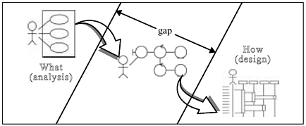
Within the ICONIX process, this simple but highly useful technique serves as a crucial link between analysis (the what) and design (the how), as shown in Figure 5-2.
This diagram explains a lot about why software development, in general, is a hard process. What we’re talking about is the need to start from a requirements-level view, where you’re thinking only about what your users need to do with the system without considering implementation details, and then driving that view of your system forward into something that’s totally focused on design. In this case, on your sequence diagram (see Chapter 7), you’re showing precisely how runtime object instances interact with each other as your system is executing. One of the most difficult problems in software development is to get from this “what” view of the world into a “how” view of the world. Robustness analysis is a technique that helps people do this.
At this preliminary design phase, you should start to think through possible alternative design strategies and technical architectures that are going to differ, depending on what technologies you’re using to build the system. You’re going to start to uncover issues related to system performance. For example, you may find that you have two objects that need to have heavy communication with each other and that these objects are remotely connected across a network. This may have performance implications for your design. During robustness analysis, you’ll take your requirements-level use case text and start making some preliminary design assumptions.
It’s curious that most of the current body of UML literature doesn’t make any mention of this concept. Our experience is that success on your projects and avoiding analysis paralysis is directly linked to using this technique.
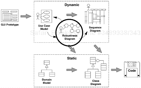
Figure 5-3 shows where robustness analysis resides within the “big picture” for the ICONIX process.
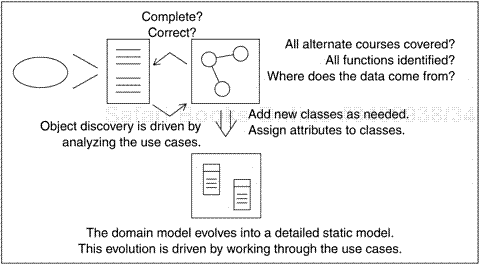
Robustness analysis plays several essential roles within the ICONIX process. Note that you will refine both your use case text and your static model as a result of robustness analysis, as shown in Figure 5-4.
It provides a sanity check by helping you make sure that your use case text is correct and that you haven’t specified system behavior that’s unreasonable—or impossible—given the set of objects you have to work with. This refinement of the use case text changes the nature of that text from a pure user manual perspective to a usage description in the context of the object model.
It also provides a completeness and correctness check by helping you make sure the use cases address all necessary alternate courses of action (which we discussed in Chapter 3). In our experience, the time spent drawing robustness diagrams toward this end, and also toward the end of producing text that adheres to some well-defined guidelines, is invariably made up threefold or fourfold in time saved in drawing sequence diagrams, which we’ll talk about in Chapter 7.
It enables ongoing discovery of objects, which is important because you almost certainly missed some objects during domain modeling. You can also address object naming discrepancies and conflicts before they cause serious problems. And, robustness analysis helps ensure that we’ve identified most of the entity and boundary classes before starting sequence diagrams.
And, it serves the role of preliminary design, by closing the gap between analysis and detailed design, as we mentioned at the beginning of the chapter.
Let’s take a closer look at the three stereotypes that we apply to objects during robustness analysis.
Boundary objects are the objects with which the actors (for instance, the users) will be interacting in the new system. These frequently include windows, screens, dialogs, and menus. If you have a GUI prototype in place, you can see what many of your primary boundary objects will be. If you follow the guidelines we gave you in Chapter 3, you can also easily pick boundary objects out of your use case text.
Entity objects often map to the database tables and files that hold the information that needs to “outlive” use case execution. Some of your entity objects are “transient” objects, such as search results, that “die” when the use case ends. Many of your entity objects will come from your domain model.
Control objects (controllers) embody much of the application logic. They serve as the connecting tissue between the users and the stored data. This is where you capture your frequently changing business rules and policies, with the idea that you can localize changes to these objects without disrupting your user interface or your database schema down the line. Once in a while (perhaps 20 percent of the time), controllers are “real objects” in a design, but most of the time, controllers serve as placeholders to make sure that you don’t forget any functionality and system behavior required by your use cases.
You perform robustness analysis for a use case by walking through the use case text, one sentence at a time, and drawing the actor(s), the appropriate boundary and entity objects and controllers, and the connections among the various elements of the diagram. You should be able to fit the basic course and all of the alternate courses on one diagram.
Four basic rules apply:
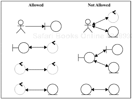
Actors can only talk to boundary objects.
Boundary objects can only talk to controllers and actors.
Entity objects can only talk to controllers.
Controllers can talk to boundary objects, entity objects, and other controllers, but not to actors.
Keep in mind that both boundary objects and entity objects are nouns, and that controllers are verbs. Nouns can’t talk to other nouns, but verbs can talk to either nouns or verbs.
Figure 5-5 summarizes the robustness diagram rules.
A reviewer of a robustness diagram should be able to read a course of action in the use case text, trace his or her finger along the associations on the diagram, and see a clear match between text and picture. You will probably have to rewrite your use case text as you do this, to remove ambiguity and to explicitly reference boundary objects and entity objects. Most people don’t write perfect use case text in the first draft.
In addition to using the results of robustness analysis to tighten up the use case text, you should also continuously refine your static model. The new objects you discover drawing the diagrams should become part of your class diagrams when you discover them. This is also the right time to add some key attributes to your more significant classes.
The flip side of the principles we just discussed takes the form of a number of common errors that we have seen students make when they’re doing robustness analysis on their projects for the first time. Our “Top 10” list follows.
These rules are in place primarily to get your text into noun-verb-noun format and to help ensure that you don’t start allocating behavior to objects before you have enough information to make good design decisions. (We’ll talk more about behavior allocation in Chapter 7, which focuses on sequence diagrams.) The rules about boundary objects are in place to ensure that you explicitly specify the boundaries of the system, outside of which reside the actor(s) involved in your use cases.
The boundary object–controller–entity object pattern will tend to appear on many of your robustness diagrams. This pattern has a close correlation with the subject-verb-object pattern of basic English sentences. You should use robustness analysis to make the text of your use cases stylistically consistent among themselves to the largest extent that you can, which will greatly improve their readability and maintainability.
You need to perform robustness analysis on all of your use case text, not just the basic courses. Much of the interesting behavior of a system occurs in the context of alternate courses, so it’s very important to analyze that behavior as part of your modeling efforts. Robustness analysis can also help you discover new alternate courses, especially when you draw controllers with labels such as Verify and Validate.
Specifying system usage in the context of the object model is the magic formula you need to build useful sequence diagrams. By naming your boundary objects and entity objects in your use cases, you take a healthy step toward getting your sequence diagrams off to a good start, by simply drawing those objects across the top of the sequence diagram for each use case.
As we mentioned earlier, controllers serve as placeholders for functionality and system behavior. You should not start assigning methods to classes on a robustness diagram because you’re not likely to have enough information just yet. You’ll make decisions about behavior allocation using sequence diagrams.
We recommend having between two and five controllers on a robustness diagram. If you only have one controller per use case, you’re likely to have a lot of very small use cases, each of which doesn’t really describe enough behavior. On the other hand, if you have more than ten controllers on one diagram, you should consider splitting your use case up into more manageable chunks.
The robustness diagram serves as something of a “booster-stage engine” that gets the process of driving use cases forward into an object-oriented design off the ground. Robustness analysis is a tool that helps us discover objects, allocate attributes, and check the use case text for completeness and correctness. But once we’ve accomplished the overall mission, we don’t need to maintain the work product. It’s a means to an end, not an end in itself.
The concept of throwaway diagrams is useful in connection with preliminary design; it is not a useful concept when it comes to detailed design. Sequence diagrams are the appropriate place for detailed design. Robustness analysis should be a quick pass across all of the scenarios you’re going to build, in order to provide maximum value to your project. If your preliminary design takes as long as detailed design, you’ll lose the benefits of this quick sanity check.
We strongly recommend that you have peer review of all of your use case text and robustness diagrams, with each reviewer performing the finger trace technique that we described earlier. You should not consider your use case done until you can pass the simple visual trace test. When you’ve reached the point where all of your use cases pass the test, the next step—drawing sequence diagrams—will be easier for you to perform than if you were starting from first-draft, vague, ambiguous, abstract use case text alone.
You must update your domain model before you can consider yourself done with robustness analysis and ready to move on to interaction modeling using sequence diagrams. You can’t allocate behavior to classes that don’t appear in your static model, after all.
The following exercises, which come from the robustness diagrams within the model for our Internet Bookstore, are designed to test your ability to spot the top 10 mistakes that people make during robustness analysis. Each page with a red label at the top contains three or four of these mistakes; your task is to write corrections on the page near the erroneous material. Following each of these pages is a page with a white label inside a black box at the top; this page contains corrected material and explanations of the top 10 rules that were violated on the previous page. Happy hunting!
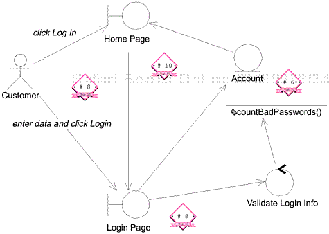
Basic Course: The Customer clicks the Log In button on the Home Page. The system displays the Login Page. The Customer enters his or her user ID and password and then clicks the Log In button. The system validates the login information against the persistent Account data and then returns the Customer to the Home Page.
Alternate Courses:
If the Customer clicks the New Account button on the Login Page, the system invokes the Open Account use case. If the Customer clicks the Reminder Word button on the Login Page, the system displays the reminder word stored for that Customer, in a separate dialog box. When the Customer clicks the OK button, the system returns the Customer to the Login Page.
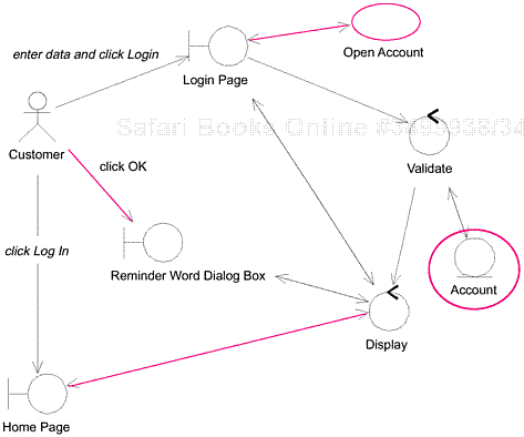
On the previous diagram:
The HomePage boundary object talked to the Login Page boundary object and the Account entity object.
The Account object had a method assigned to it.
No alternate courses were represented.
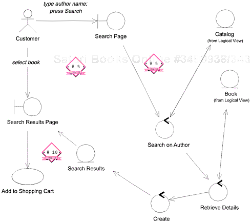
Basic Course: The Customer types the name of an Author on the Search Page and then presses the Search button. The system ensures that the Customer typed a valid search phrase, Author and then searches the Catalog and retrieves all of the Books with which that is associated. The the system retrieves the important details about each Book.
Then the system displays the list of Books on the Search Results Page, with the Books listed in reverse chronological order by publication date. Each entry has a thumbnail of the Book’s cover, the Book’s title and authors, the average Rating, and an Add to Shopping Cart button. The Customer presses the Add to Shopping Cart button for a particular Book. The system passes control to the Add Item to Shopping Cart use case.
Alternate Courses:…no search phrase…no books found…Customer exits before searching…

The sytstem retrieves the important details about each Book and creates Search Results with that information. Then the system displays the list of Books on the Search Results Page….
On the previous diagram:
There are too few controllers. Verify Search Phrase enables the system to avoid performing a search with no search phrase, while Display is a standard controller associated with Web pages. (These controllers also reflect alternate courses that the previous diagram didn’t.)
The Search Results entity object is talking to the Search Results Page boundary object.
The use case text doesn’t reflect the creation of the Search Results object.
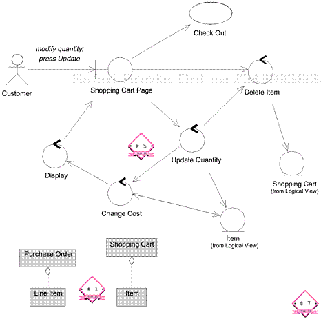
Basic Course: On the Shopping Cart Page, the Customer modifies the quantity of a Line Item in the Shopping Cart and then presses the Update button. The system stores the new quantity and then computes and displays the new cost for that Line Item. The Customer Presses the Continue Shopping button. The system returns control to the use case from which it received control.
Alternate Courses: (1) If the Customer changes the quantity of the Item to 0, the system deletes that Item from the Shopping Cart. (2) If the Customer presses the Delete button instead of the Update button, the system deletes that Item from the Shopping Cart. (3) If the Customer presses the Check Out button instead of the Continue Shopping button, the system passes control to the Check Out use case.
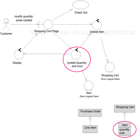
On the Shopping Cart Page, the Customer modifies the quantity of an Item in the Shopping Cart, then presses the Update button. The system stores the new quantity, then computes and displays the new cost for that Item.
On the previous diagram:
The Change Cost controller is unnecessary, since both it and the Update Quantity controller operate on the Item object.
The use case text refers to Line Item, but it’s clear from the class diagram excerpt and the robustness diagram that the text should refer to Item instead. (This kind of name usage inconsistency can be deadly.)
The class diagram excerpt doesn’t reflect the attributes that are mentioned in the use case text.
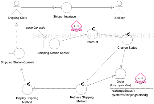
Basic Course: The Shipping Clerk ensures that the Items listed on the packing slip for the Order match the physical items. The Clerk waves the bar code on the packing slip under the sensor at the shipping station. The status of the order is changed to “shipping.” The Shipping Method is displayed on the Shipping Station Console.
The Clerk weighs the set of physical items. The Clerk packages the Items. The Clerk attaches a manifest appropriate for the given shipping method. The Clerk waves the bar code on the manifest under the sensor. The Clerk sends the package out via the associated Shipper.
Alternate Course: If the Shipping Clerk finds a mismatch between the Order and the physical items, the Clerk stops processing of the Order until he or she is able to make a match.
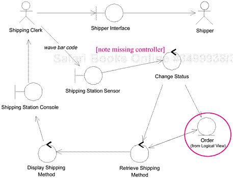
The system changes the status of the Order to “shipping.” Then the system retrieves the Shipping Method that the Customer specified for this Order and displays it on the Shpping Station Console.
On the previous diagram:
The Interrupt object is a construct that belongs to detailed design.
The Order object had methods assigned to it.
The use case text is in passive voice and not as precise as it should be relative to the robustness diagram.
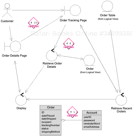
Basic Course: The system retrieves the Orders that the Customer has placed within the last 30 days and displays these Orders on the Order Tracking Page. Each entry has the Order ID (in the form of a link), the Order date, the Order status, the Order recipient, and the Shipping Method by which the Order was shipped. The Customer clicks on a link.The system retrieves the relevant contents of the Order, and then displays that information, in view-only mode, on the Order Details Page. The Customer presses OK to return to the Order Tracking Page. Once the Customer has finished viewing Orders, he or she clicks the Account Maintenance link on the Order Tracking Page. The system returns control to the invoking use case.
Alternate Course: If the Customer has not placed any Orders within the last 30 days, the system displays a message to that effect on the Order Tracking Page.
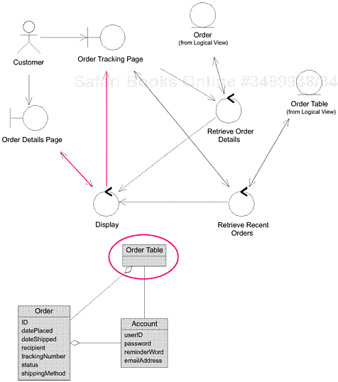
On the previous diagram:
The Order Details Page boundary object is talking to the Order Tracking Page boundary object.
There’s no indication of what happens if the Customer hasn’t placed any recent orders.
The class diagram excerpt doesn’t reflect the (newly discovered) Order Table class.
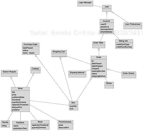
Figure 5-6 shows the class diagram that includes some of the attributes on the classes for our Internet Bookstore.
