Chapter 3
How Do Hypervisors Work? How Does IaaS Function?
3.5 Scaling through Software Architecture or Hardware
3.6 Motivation or Need for Scalable Architecture
3.7 Scalable Architecture (of Software)
3.10 Summary of Capabilities of Hypervisors
3.1 Introduction
It is essential to understand infrastructure as a service (IaaS) as a pre-requisite to understanding the remaining concepts in this book. This introductory chapter is oriented to give a conceptual view of how hypervisors work and how IaaS function. This conceptual understanding is what is required for (solution) architects for the following:
- Architecting software solutions (not as SaaS) for IaaS (Chapter 4).
- Architecting cloud Software as a Service (SaaS) software with non- or semi-cloud compatible products (Chapters 7 and 8).
- Architecting cloud compatible cloud SaaS product (Chapter 9) to launch on using public or private IaaS.
- Architects, it covers the pre-requisite knowledge for deploying solutions on IaaS.
Definition
At its simplest level, IaaS is a system by which hardware servers (to deploy any software solution) can be provided as a service and accessed from a public Internet.
Amazon Web ServicesTM and Microsoft AzureTM are great examples of such IaaS sites. Users can create an account on these sites and then proceed to specify the type of hardware that they require. This specification can include the number of core CPUs required, main memory required and also secondary storage required. Most public IaaS providers offer pre-configured sizes in terms of the number of cores, processor speeds and the main memory amount. The bundle of CPUs and memory sizes are very often made available in idealized configurations, referred to as ‘small’, ‘medium’ or ‘large’. Users can request one or more ‘instance/s’ of any of these sizes and are charged on a monthly basis as per the usage of CPU time and memory or secondary storage usage sizes.
Note: Users can also specify their entire organizational requirement, based on their intended infrastructure deployment architecture.
Therefore, sitting in front of a Web browser, users can allocate some machine instances as, for example, a load balancer and simply attach a few other instances as parallel machines under the load balancer.
Users (not end users but typically those who allocate hardware resources to project teams in infrastructure support teams of enterprises) can also specify (which) operating systems to run on each of those instances, as well as other infrastructure software – such as application server or RDBMS – that need to run on each instance. Finally, users can load the application software on this server or hardware machine and run it.
3.2 Hardware Virtualization
Having understood the typical user experience and services that users can get from IaaS, we will now turn to the other side to see how service providers can provide these infrastructures as a service.
Through the use of IaaS, most users such as those that handle HTTP or HTTPS requests that are initiated through Web browsers.
This is true both when servers are accessed in a LAN environment or through public Internet.
Just as how files are organized in a file system, hardware servers in data centres are organized hierarchically, and given a virtual name or address. At each node of the hierarchy, a table is maintained to map the virtual name or address to a physical name or address of the hardware server. A request (such as http or https) from any Web client is addressed to a particular server using its virtual name. The table at each node helps in decoding and directing the request to physical location of the specific server. For example, if the virtual name is ‘www.google.com’, it will be decoded to map to an HTTP server which, in this case, is http://www.google.com.
Such an arrangement gives freedom to locate the physical hardware server and access it from anywhere in the network. If the network is the combination of LAN and public Internet, given access rights, clients from anywhere through the public network can access any of the other servers within the LAN.
In addition, if one physical hardware server is down, the table can be altered to point to another physically good working hardware server that is physically located elsewhere and having different physical address. Thus, the time required to correct fault of a hardware does not affect system availability to users.
Similarly, any hardware server upgrades or software upgrades that are running in the hardware server can be done with least impact on availability of the servers to users. This is done normally by doing upgrades and maintenance on a parallel similar server on the LAN/network, and by finally changing the physical address to point out this new updated server.
This is the basic first step or simplest model explaining hardware virtualization.
3.3 Auto-Provisioning
Let us examine the next logical step in this virtualization.
If one could automate the above functionalities, then the resultant would be referred to as ‘auto-provisioning’.
Below is a scenario to explain this feature.
Assume there are approximately 1,000 hardware servers connected on a LAN.
- Users send an http request from their thin client to one designated http server in the LAN.
- Users typically send a request to allocate one instance of small, medium or large server (see Section 3.1.1 definition for description of ‘small’, ‘medium’ or ‘large’ server).
- A software program running in the http server processing the request looks up a table and identifies one free hardware server.
- The software program looks up a pre-designated table for locating any free hardware server.
- Passes on the virtual address of the same to the requesting client.
- This software need to perform other functions too:
- Track usage of this hardware.
- Raise a bill to the user on every month according to the usage.
- When the user relinquishes the hardware after their need, the software also should mark the hardware free and stop billing.
- User gets the virtual address and carries on the necessary usages on it until they inform to relinquish.
The above describes an ideal normal flow. This process of automating the provisioning of hardware server is referred to as ‘auto-provisioning’.
3.4 Data Centre Rack Systems
Conventionally, servers are arranged in independent casings. Servers under a typical hypervisor need not necessarily be in this arrangement.
A typical IaaS provider will need to have 1,000s of servers under one data centre, and every moment one or several of servers will be allocated or released.
A convenient form is to have rack systems. For instance, assume a rack full of CPUs with several printed circuit board (PCB). Each board can contain only two, four or eight core CPUs; and in this way, several boards can be inserted one below the other in the rack.
Similarly, a separate rack can contain several PCB boards and each board can contain only memory chips.
The ability of the ‘hypervisor’ software is to slice and dice the CPUs in the CPU rack and combine them with specified amount of main memory, available in the memory rack. Thus, it can create one instance of a server with the specified number of CPUs and main memory. Thus, one instance can act like a virtual machine. This is normally referred to as ‘bare metal’ in cloud computing parlance.
Users can specify the operating system they want to load onto the bare metal. Users can also specify a certain quantity of secondary storage memory to attach to the virtual machine. Normally, secondary storage is available as a SAN – which is a huge contiguous memory from which a specified portion will be allocated to the virtual machine or user can configure it to serve as a backup memory for the entire set of machine instances.
From the above description, it is now clear that
- Hypervisor will be closer to the bare metal than the operating system itself.
- Hypervisor will have the power to terminate an operating system, whereas an operating system running in hypervisor cannot terminate the hypervisor. This indicates that hypervisor is the fundamental software in IaaS. Many operating systems and many instances of same operating system can be simultaneously running in one hypervisor instance.
- It will also have the power to dismantle a particular machine instance and return CPUs and memory of the instance/s to their respective common free pool.
- The term ‘hypervisor’ is used in this book to refer to a class of software that has the core functions discussed in this chapter. It is very similar to use of the term ‘operating system’ to refer to a class of software. There are many hypervisors available in the market both commercial and open-source products. Hypervisor is key software to create and provide IaaS. Readers can refer to[24] for other software components required to formulate and offer a complete IaaS. Such a discussion is out of scope for this book.
There are many hypervisors now available. Some of them are freeware and a few are commercial off-the-shelf (COTS) products.
3.5 Scaling through Software Architecture or Hardware
Over the past decade, we have constantly been working towards architecting highly scalable software systems. ‘Scaling’ here refers to the ability of the system to accommodate more users (or) scaling to process more data volumes (or) where more computational power is required, and it is typically achieved by a combination of both software and hardware.
Scaling is specifically achieved by two important aspects of the software architecture:
- By software architecture
- By deployment architecture
How a software is architected influences the scalability of the resultant software. Software architecture also dictates/determines deployment architecture. This in turn determines the feasibility of adding processing power or memory to specific heavily-used modules.
The software architecture and hence also the deployment architecture should be amenable for adding more processing powers as and when more users (or) data load (or) computational power are demanding the system.
3.6 Motivation or Need for Scalable Architecture
When architecting a system, it is difficult to predict how many concurrent users will try to access the system during peak usage.
That means system has to be architected for handling maximum number of concurrent users or logged in users. Therefore, at the start of deploying the solution itself, the number of servers that have to be procured is for maximum number or peak load of users.
The obvious disadvantage of this design is that the amount of hardware resources allocated will be too large or sub-optimally used in off-peak times. The risks in this design are as follows:
- Peak load envisaged may or may not be happening in post-implemented production situation.
- It may take more time, for example, such as 3 months or 6 months or 8 months to reach the envisaged peak usage and hence experience peak load; and hence experience peak usage at later time from launch than sooner.
Hence,
- Capital investment required for implementing the system will be too large.
- The capital investment is not properly utilized.
- Thus, initially calculated ROI would not match with actual ROI.
- Therefore, the break-even period becomes unpredictable.
- This uncertainty comes into play because of the inability to accurately estimate the peak load and the time to reach the peak load.
There are possible alternative scenarios too:
- Actual peak load may be much higher than that estimated peak load.
- As the system usage becomes more and more popular, more and more users may join to use the system.
- To set up a near scalable environment for testing a system, whose usage has increased enormously, is also a major concern’.
In this scenario to handle unanticipated additional peak load, one need to add additional hardware. There is a minimum lead time for procuring the servers and installing them. Usually in bigger organizations, it is of the order of 3–4 months even in the best optimized procurement cycles. During this time, users will feel slow response, and hence will get frustrated and may leave using the system.
3.7 Scalable Architecture (of Software)
Now let us see how software architecture helps achieve high scalability. To achieve higher scalability, the architecture needs to be multi-layered1 and multi-tiered2 and also highly modularized into components.
Note: 1What is layer? Layer defines the application to break up into logical structure such as presentation (UI), the business logic (processing) and data access (to access the data). 2What is tier? While layer is logical, tier defines how these layers will run whether in the same physical server (or) different servers.
To achieve scalability, the components of cloud SaaS software, namely layers, tiers or components, will be distributed over networked servers; one or more servers will provide computing power to each component or tier or layer. As discussed in Chapter 10, software architecture consists of two main elements:
- It is distributed architecture; it is on a multi-tiered architecture style. An example is popular three-tier model – Web tier, business tier and data tier.
- Each tier may consist of one or more components, for example
- business tier may have components such as bpm, business rules engine, etc.
- data tier may have further more components: data access object, database management system and data storage.
Such a software architecture will have a convenient corresponding deployment architecture: Generally, as a rule of thumb, each tier will be supported by one set of hardware servers.
If there are more than one significant components in any tier, then each of the significant components is housed in a separate hardware server. For example, business rules engine is a component in business tier and as a part of ‘design’ one or a cluster of servers can be allocated for business rules engine alone.
By assigning one or more servers to each tier or each significant component, we can provide adequate processing power that is required to handle appropriate number of concurrent users. There exists an equation connecting between the processing power and memory of servers to the number of users (requests) it can handle. If more number of users come, then additional units of server need to be added at that point – the component or tier – which becomes bottleneck in completing turnaround of users’ requests.
Let us take a scenario to explain it further:
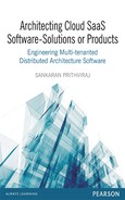
- Let us assume an architecture for a hypothetical software as given in Figure 3.1.
- An http request coming from user client: Various tiers and components in the software will come into play to process the request.
- Figure 3.2 gives a sample sequence of tiers and components that will come into play for satisfying the request. (Sequence diagram of UML is the most appropriate way of describing this. For some common understanding, a non-ideal notation is used here.) Each tier or component will process its own part and return a value; that is why there is an arrow that is travelling back to the Web tier.
- Let us assume that one hardware server is provided to support each one of the tiers or for each one of the major components in any tier.
- For simplicity sake and discussion required for this chapter, we have assumed same configuration for all the servers.
- Let the server configuration be 1.7 Ghz quad core processor with 8 GB of main memory.
- Some of the tiers or components may require more processing power since they may perform CPU bound operations, for example business tier components. How many concurrent users can be accommodated in a given server configuration is normally done as part of ‘capacity calculation’: This is not a very precise engineering calculation. There is not any unique satisfactory method available for it. Every senior architect in the field develops her or his own method and follows it. For most of the projects, some of the following suggestions may be useful:
Figure 3.1 Various components in 3-tier architecture
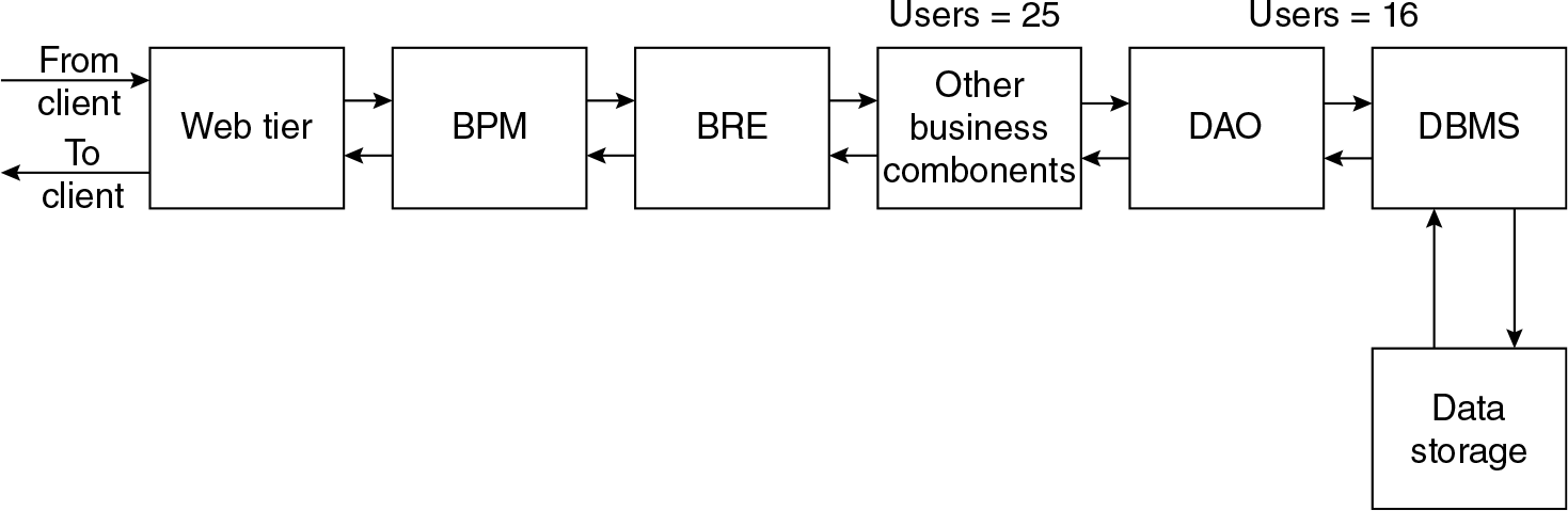
Figure 3.2 ‘Sequence diagram’ of a system
- A load test can be used to practically find out how many number of users a server can accommodate without the response time being adversely affected.
- Sometimes, a stress test (i.e. loading the system progressively with more and more number of users) is conducted from all angles (UI, data access) for testing to determine correct deployment solution.
- One can calculate the number of Java objects that have to be processed by the CPU for processing the request at each module in the pipeline. From there, one can calculate how many number of users can be processed ‘concurrently’. Similar method is available for .Net objects too.
- Some software product vendors provide ‘calculators’ for arriving at deployment architecture; for this calculation, inputs are number of concurrent users and simultaneous logged-in users.
- Using one of the above or any empirical methods that will help in arriving at how many number of maximum users can be accommodated in a given configuration of the server at every stage. An example of the number of users at every server is mentioned in the diagram.
- Some of the tiers may perform memory intensive operations. Example for this is data tier. For every connection to DataBase in connection pool, about 512 MB of memory is required. Therefore, in 8 GB machine there could be a possibility of accommodating 8 × 2 = 16 connections.
- Therefore, data tier cannot accommodate more than 16 concurrent users in this example solution deployment architecture.
- That component or tier that can process lowest number of concurrent users may mostly be bottleneck and determines the total number of concurrent users the entire system can handle.
- If we provide necessary processing power and required memory to that lowest processing component, then the bottleneck will move to the next slower processing component or tier. By that, we mean thus:
In this example,
- Only data tier alone can process not more than 16 user requests at any point of time.
- If we add one more server to data tier of the same configuration, then the processing capability gets doubled to 32 current users.
- Now from 16 to 32 users, the data tier will not be bottleneck. But after 25 concurrent users, component aa will become the bottleneck; unless and until the processing ability at this component aa is not increased, the whole system throughput cannot be increased to handle more than 25 concurrent users (without users experiencing a dramatic drop in response time).
Thus, the multi-tier, highly componentized software that can be on a distributed hardware servers – each hardware server supporting one or more tier/s or software components – are said to have architected for scalability or said to have scalable architecture.
Horizontal Scaling vs Vertical Scaling
In actual production situation, when there is a need to processes more users (requests) at any component or tier (as demanded in the above situation). There are two ways of adding additional computing power as described below:
- Vertical scaling
- Horizontal scaling
Vertical scaling means the processing power can be improved in the same server. For example, in the previous scenario, we have assumed quad core with 1.7 Ghz processor. To achieve scaling, we can replace this with higher speed processor, such as 2.3 Ghz still can with quad core processor.
Horizontal scaling means adding one or more servers of the same CPU with same processor speed and memory size. Therefore, two or more servers will work in parallel. In practice, this is usually even extended to make three servers work in parallel. (Why only up to three and why not more such as four or five is left as exercise to readers). All the two or three servers will have the same software – be they module or tier.
How to coordinate among these many servers to make them appear as if additional computing power is provided to process more number of user (requests) needs a coordinator; or technically, it is called ‘load balancer’.
A bunch of servers serving same module is referred to as cluster. It is also referred as a node since it runs only one component of the entire software. In addition, it may be referred to as node because all the three or so servers may sit on the same node of the network of servers.
3.8 Concept of Load Balancer
To ensure proper coordination between two or more machines, working in parallel, supporting the same component (or tier or module) in a software, a new additional component by name ‘load balancer’ is needed.
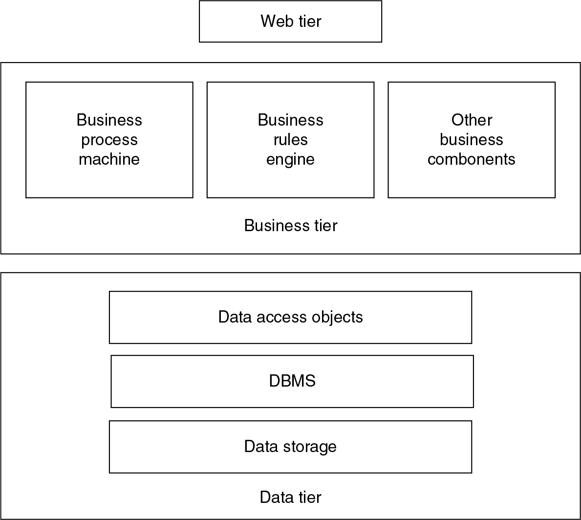
Figure 3.3 pictorially explains a function of a load balancer that has three server instances among whose the load is balanced. Here, the load balancer is a typical hardware (bare metal) machine. The combination of all servers under one load balancer is said to be ‘cluster’. Network load balancers (NLBs) can be software also in which case they will be installed in all the servers under one cluster.
As the name indicates, load balancer keeps monitoring workloads at each of the servers connected to it.
The workload is nothing but object codes that are queuing in front of the CPU for getting processed or serviced by CPU.
Figure 3.3 Schematic of ‘Load Balancer’
Load balancer moves workloads between the servers that are relatively free.
Therefore, load balancers constantly keep monitoring workloads or queues in front of CPU as well as free CPU or memory available at each of the servers (which are connected to the load balancer). Load balancers in a cluster keep communicating the workload and free/busy of CPU + memory information among themselves and later move the objects among the servers in the same clusters to get the processing ‘attention’.
Load balancer can be another physical hardware, or it can be purely only software too. Sometimes, software load balancers are also referred to as NLBs.
One copy of NLB will be installed in each of the servers that are expected to work in parallel. Obviously, the server being hardware it would have been connected by highspeed LAN environment.
The load balancer (MicrosoftTM uses the acronym ‘NLB’; and NLB is also Microsoft’s software and not a physical hardware) normally supports both algorithmic and deterministic approach to manage or distribute the load among the servers under one cluster.
The above explained how a load balancer works and also explained how it helps in scaling.
The functionalities of load balancer are also moved into hypervisor.
3.9 Auto-Scaling
Let us examine how to achieve high scalability using hypervisors and the modern rack systems described above. This knowledge is essential as an introduction to understand auto-scaling.
By combining two major functionalities – auto-provisioning and load balancing – we can expect hypervisors to do automated scaling function. This is explained as below:
- Assume a script can run in hypervisor.
- The script has two parts:
- One is called ‘cloud watch’
- Second part does the following:
- Ask for required server through auto-provisioning feature of hypervisor and
- Load required software + load software component or tier to which it goes as additional server to handle.
- About ‘cloud watch’ pattern: one can specify to ‘cloud watch’ to observe certain happening phenomenon such as keep monitoring and counting <number of users <at a tier>> and can specify to trigger <some actions> on <a condition such as greater than x number of users in this tier> <do something>.
For example, keep monitoring the number of logged-in users newly arriving at web tier;
If the number of logged-in users increases beyond 1,000, then add one more server to web tier.
- The trigger is used to carry out actions such as auto-provision another server instance using step (c).
- Now change the server to be monitored (such as next would be bottlenecking server) and go back to step (c).
- Thus, the above algorithm will ensure that servers are automatically provisioned as and when the number of users keep increasing.
- (Obviously, there is an assumption that there are enough number of servers available for making this happen).
- The above script can be made much more comprehensive by writing a separate loop for de-provisioning as and when the number of users come down.
- The de-provisioning loop will keep removing servers as and when the number of users come down in the right (reverse) order.
Since it is a script,
- It can be modified any time.
- It can be parameterized.
- It can be written for any deployment architecture.
- ‘Cloud watch’ can ‘watch’ the key items that architect wants it to ‘watch’ for taking some specific action.
Thus, through this kind of scripts, complete scaling required can be automated.
3.10 Summary of Capabilities of Hypervisors
- Hypervisor can create virtual machines (which is referred as an instance of server) to specification by combining CPUs and memories from rack systems.
- Server instances can be requested remotely through cloud and Web browsers and hypervisor can provision it.
- It can also load required software such as operating system and specified other software too.
- Server instances can be automated to provision to specification.
- The functionalities of load balancer are also included in the hypervisor.
- Using cloud watch capabilities, auto-scaling is possible.
- De-provisioning is also possible.
- In commercial public IaaS, other operational and business support systems such as to monitor the usage of servers and raising bill according to the usage is also available.
3.11 A Simple Model of Infrastructure as a Service (IaaS)
The following description will give an idea on how IaaS is organized from service providers’ perspective. This model will help in architecting solutions for IaaS as discussed in Chapter 4; it will also help in subsequent cloud SaaS solutions being discussed in rest of the chapters.
- Assuming availability of rack systems of CPUs and memories; also availability of SAN.
- All these ‘bare metal’ is under hypervisor.
- The user can interact with hypervisor using their Web browser for provisioning requests; auto-provisioning is possible by hypervisor.
- A billing system takes care of prepare bills for every user as per the usage of hardware.
3.12 Example Case Situations
Example 1
Start-ups and uncertainty and unpredictability for system usage consider a situation such as for the first time an application such as FacebookTM has to be launched. The creator of FacebookTM is completely uncertain how this will be welcomed in that open market. Implying that it is impossible to predict how many number of logged-in users or concurrent users will be there for this system. It is also impossible to predict the peak or turf loads for this system*
- If we assume any number and it is likely to go wrong
- If one predicts a large number of users and procures a large amount of hardware, then a huge capital investment is required; and this is not practical.
- If a small amount of hardware is used, thinking it is first-time launch or announcement to the public, then
- The use of the site and services becomes so popular; and if a large number of users land on in that site to avail the services, then the hardware would not be in a position to support that many users, and hence the performance will fall down drastically.
- This will frustrate the users and likely that they may stop using this or may go to alternative competitive sites and services.
- Public IaaS will provide complete ‘elasticity’ of the hardware that are required for this situation.
- It will do an auto-scaling and hence will also provide automatically additional computing power necessary to handle new spurt up users.
- If the users come down, the system also will be de-provisioning and de-allocate the hardware and shrink it to minimum required level.
- The charges for using hardware are directly proportional to the duration of the time for which they are used.
- No initial investment. All ‘pay as you go’.
Thus, opting for public IaaS matches this kind of requirement perfectly in many ways:
- Initial investment for starting it can be kept as minimum as possible. Since the use of public IaaS is only on pay-per-use model, there is no investment for hardware servers.
- Public IaaS can be assumed to have an infinite computing resources. We can assume the hardware can automatically scale-up to meet any peak-demand.
- Additional expenses and hence pay-out to IaaS for additional usage of hardware service is in proportion to income due to additional users.
Thus, opting public IaaS is good solution for this kind of start-up situation.
Example 2
Seasonal peak demands in North America or Europe during Christmas season
There are many systems that are deployed for sales promotion. Similarly, in India during Diwali festival time, a lot of sales promotion systems are put in place.
Such systems are typically used for 2 or 3 months. During the time, system will be in peak use. After that, the system may not be having any use, or it may be at the lowest use just to keep maintaining till next season.
Investing to buy hardware for such systems will unnecessarily eat away corporate IT budget.
Use of IaaS is appropriate.
Example 3
Sports event or event management
Federation of International Football Association (FIFA) kind of organizations conduct sports events such as FIFA’s World Cup once in 4 years. They also conduct other events such as European champion of regional or local championships. Thus, on the whole, they are busy throughout the year.
FIFA maintains websites for each of the events. Each website becomes very busy a few months before the start of the event. That means, the site users will be large, and it will be increasing as the date to event increases. After the event, the users will come down drastically.
A typical event such as FIFA’s World Cup may past for 40 days. Even during the event time depending on which team wins at a particular stage such as second round or prequarter final, number of visitors to site may peak.
For such highly fluctuating load of users, dynamic-auto scaling through IaaS is an ideal solution.
3.13 Summary
- This chapter introduced the architectural attribute ‘scalable’.
- It has discussed two traditional means of achieving scalability through ‘horizontal scaling’ or ‘vertical scaling’.
- This chapter also discusses how software needs to be architected, help as well achieve scalability.
- In this context, this chapter also discusses how IaaS supports ‘auto-scaling’ and handles fluctuating incoming loads and also optimally utilizes the hardware in proportion to load.
- The role of load balancers and software load balancers are introduced.
- A summary of functionalities of hypervisor will be useful for architecting solutions for IaaS.
- Use cases presented here will be useful for concretizing readers understanding on these areas.
- In this context where ‘hypervisors’ fit in and make up IaaS is also described.
- Thus, the knowledge of how hypervisors work and how IaaS function are good prerequisites for architecting solutions discussed in Chapters 4, 7, 8 and 9.
- The simple model of IaaS discussed here will be very useful for solution architects.